LabVIEW graphical table
I'm reading the modbus data and I have a table of data that I need to graph, deepening on the iteration of a loop for I want to lead the right struture data and plot it.
What intrigue should I use, x-axis are time in all cases. Should the table be unbundled first or hidden instead?
Well, some of your graphs seems to have several tracks, so you have to rearrange the data a little more. Here's a quick attempt, but please change if necessary.
Tags: NI Software
Similar Questions
-
I have fixed this problem in the past, but not fitted with a filter. When I run my VI the graphic polts my data from right to left. How can I change to draw from left to right? I tried to change the entries in table without result. Any suggestions? I'm fairly certain that it is an easy solution, but with my limited knowledge of LabVIEW I run out of ideas for patches. Any help would be appreciated. Thank you!
Change the property of the x-axis in "reverse".

-
I have a loop for. Inside the loop for, there's a XY Chart, including indicator I in the façade. I would like to have the graph not inside the loop, but outside, with indexing enabled. Now I want an array of graphs, in order to have available ALL the graphics created (one for each iteration). But I'm not able to create such a chart table. I am able to create and indicator data (it turns out to be a 2d cluster of 2 elements array (1 d table 2)).
Y at - it hope to have what I want, it's the graphics N of iterations of the loop?
Try to place the graphic in a cluster container before putting it in the table container, also add a node single-height bundle just before the tunnel exit of the loop autoindexing.
What kind of data are your xy charts? (table of cluster of points, cluster of x and y, complex tables, etc.).
It would be useful that you could fix a small example of your code so that we can see how you build the data graph.
-
It is probably a very stupid question, but I tried for a few hours to avoid to ask this on the forum.
I have attached a screenshot of a graph and table in my VI in LabView. Both receive the same data in a file hard file saved another VI data capture. The graph represents correctly the data, while the table of cluster data in a cycle in a slice of time instead of 'paint' it correctly over time.
Can someone help me? I must be missing some time that me is featured in the face! Thank you, Bill
Solved the problem!
Added a convert from data Dynamics table 1 d of scalers and return to dynamic data. Now, I get the good wavepattern as expected.
See the attached diagram.
-
Return the execution of DLLS in Labview data table
Hi all
I have a DLL C++ which should run continuously collect new data of some hardware.
I can call the DLL without any problem of Labview, but I wish I had access to some digital table data in the DLL in Labview (the appellant or an another VI) during its execution.
Working in this direction, I've already got the event validation works, i.e. trigger messages to the DLLS running in VI of the caller using PostLVUserEvent(). This would solve my problem (maybe bad) if I need only a scalar or string of each event (which works fine).
Then I tried passing a few paintings of small integers via the event (properly by changing the input type to create the user in LV event), but it did not work (empty tables or falls down... oops!). Perhaps events are not the way to send large paintings (say 10 ^ 4-10 ^ 5 integers) anyway...
Can anyone suggest a way to do this? There are functions to manipulate the values in a control of LV/indicator of the DLL running?
Thanks a lot for any assistance, MT
-
Can I plot the data in a graphical table of references?
I have a request, when the customer asked 12 plots on a single screen. These plots data in a table. It would save me a lot of time if I could make a table of controls and wire then the data that their using a structure. I tried to do this with an array of references to my maps, but it doesn't seem to be a way to add data to a chart by using a reference. This seems a little strange because you can do so many things by using a reference, I guess that you can use to add data to the chart. I feel that I checked the list of properties and methods well enough, but maybe I've misunderstood something.
If you add new values for parcels (ie. you have a table of 12 items for 12 cards), you could do that. I use the invoke with chart labels strategically selected node. If your labels are not strategically chosen, simply create an array with their respective labels.
-
How do I change mouse cursor over a graphic, graphic, table, or PivotTable in 11 g
Hi all...!!
I tried to change the shape of the hand to an arrow cursor.
As we know whenever the mouse cursor is over any button or PivotTable dynamic, graphic or graphics, it turns into a form of hand, I wanted to keep it in the form of default arrow.
It is obiee 11g.
Help, please.above ground only help you see the cursor on the local machine
to make it visible on all machinesColumn Goto properties > additional CSS > css write cursor: default
then save the wide system for these types of data changes
Also make the same changes in other types of data as...see you soon
Ankit
-
Insertion of graphics, tables, etc.
Most of the time, pretty look bad graphics I have insert into documents. I have tried to copy - paste (almost never of work), save it as a graphics file (.gif, .jpg, etc.) and even print to PDF and inserting them like that. Some come out very well, but most is blurred. I can't imagine that a program designed specifically for the creation of publications would do a mediocre job of graphic display, so there must be a good way to do that I have not discovered. Can anyone help?
I use CS4 on a Vista machine and as you can tell, I'm a novice user.
GIGO means "Garbage in Garbage Out" http://en.wikipedia.org/wiki/Garbage_In, _Garbage_Out
To get these images, if you want quality any PowerPoint the best option would be to get the PDF version of each slide.
I have a book that I do every year involving slides from PowerPoint, and I make PDFs of powerpoint slides and insert them in print in InDesign.
Word/Powerpoint could be able to their output and they look ok, but it's a question how you find them in Word/Powerpoint in Indesign.
-
How to make the button to set the properties of auto-scale one of the Axes on the graphical indicator so I can turn on or off when I press on it.
I need to change the adjustment vaguely Autoscale property for my graphic indicator. Can someone help me please.
Thank you!
Hello
I have confirmed that there is currently no way programmatically enable/disable autoscaling for axes on the LabVIEW graphical indicator generator of the user Web interface. We noted this to possibly be implemented in the future; Sorry for the inconvenience.
-
By the way the table of Clusters with binary strings via adapter LabVIEW
I need to go through LabVIEW adapter table clusters containing binary strings.
These data will be subsequently stored in the MySQL database.I need to force the option "Binary string" for the ValBinary element, even if my output array is empty.
Is this possible?
Used versions: TestStand 4.2.1 + LabVIEW 8.6.1
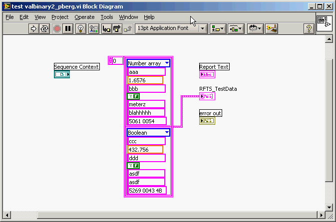
Attached file: valbinary2.vi containing the clusters of test output array.
Howdy Jean-Louis,
My apologies, I'm not quite your question. You're right that LabVIEW does not know that a string is a binary star strong; LabVIEW, chain stores in a format of Pascal, looks like all the strands in the same way. Because TestStand stores strings in the C type format, on the other hand, the null (0x00) characters can be confusing when interpreting strings in TestStand as you learned to understand. That is of course why TestStand offers the feature to interpret strings as binary strings.
As Sylvie refers to his post, to illustrate his point I created within TestSTand an array of the same type of data customized to store past out of your valbinary.vi of test data. Test patterns, I also edited the outputsome constant values to the cluster VI. (See the following screenshot). Note that the last string (named ValBinary) in the cluster contains a hexadecimal string with a null character that is inserted as the 3rd on-screen character (before the actual end of the string).
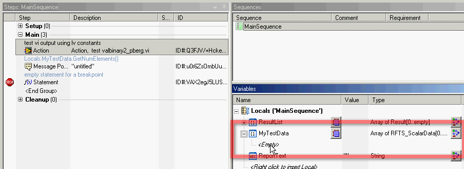
Here is a screenshot of the created sequence file that calls the VI and then displays the number of items in the table from the VI to the user. Note that the Locals.MyTestData table is empty before the execution of the sequence.
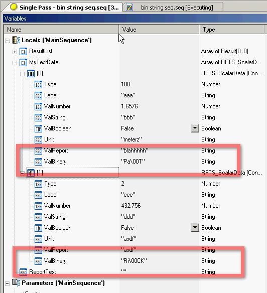
Finally, as the execution of the sequence, I opened the Variables pane to view the contents of the Locals.MyTestData table. Here, I have confirmed that the "binary" string of LV was successfully passed in and stored by TestStand.
Finally, the popup message in the second step of the sequence shows indeed a message indicating there were two elements in Locals.MyTestData.
This sequence has been able to run successfully even without manually specifying a size of Locals.MyTestData beforehand. TestStand dynamically allocated the necessary elements to store the results of test valbinary.vi.
-
How to display 4 charts on the same graphic screen when executing the VI 4 times?
My goal is trying to show 4 different graphs on the same XY graph when I run the VI 4 times. Right now, the new graph will be to saturate the previous graph when I re - run the VI.
Help, please!
You need a mechanism to store the previous data; LabVIEW graphics have no history, they display data sets. A shift register is an obvious answer, but it can be a little 'tricky' when the XY graph build is used because it accepts a DDT and you can not simply add a data set using table functions...
The solution?
Rather than make the changes for you, I created a simple example for a regular graph to show you how to use an uninitialized shift register to store values of previous test cycles (data will be lost when the VI is closed) while the VI is in memory.
I'll let the conversion of the DDT in the 2D-table and graphical execution XY for you to understand where it is a form any duty.
Good luck!
-Bob
-
little binary string in array (of TCP read) to the table of Boolean LV (and back)
I would like to ask what is the easiest way for the next conversion? We use aTCP Read function to read an incoming binary string to a S7 API using LabVIEW. We know that LabVIEW stores a Boolean value to 8 bits. The incoming binary string contains 14 bits (representing 14 indicators of status). What is the best way to convert these values of 14-bit LabVIEW Boolean table?
In addition, we send a LAbVIEW Boolean table in the PLC data (to write a TCP) string containing status bits.
Thank you very much!
Martins wrote:
This 30 bytes contains some data more, including 14 bit flags (size is 14 bits). Since the PLC cannot put 'together' (16-bit) words at his side before sending data TCP, 14 bits is padded with 2 bits holding no valueable info.
Then the solution is simple. Take your 2 bytes and unflatten in a U16. Then use Boolean table number.
-
convert variant table 2D in teststand
Hi all
I would like to convert an object of the type variant in a table in TestStand. Specifically, I get data from an Excel sheet (calling several methods on different objects obtained from ActiveX of Excel in TestStand). These data are of type Variant (from the call to the Range.Value2 property).
I know it is possible to convert a 2D inside Labview (VariantToData) table, but also leave in TestStand? If I do not use any method of conversion and just assign the return value of Range.Value2 directly to an array of strings 2D, the data did not order how to know (the first dimension of the array corresponding to lines and the second to the columns of the Excel table) and the array index starts at 1 instead of 0.
Yes, there is a function VariantToData equivalent to TestStand I can use?
Thank you
Hi Zladidad,
There is a tool integrated in Teststand used to this exact: it is the dialog "properties of the Tools-> Import/Export. You can save a file that contains your settings and then adapt the copies of this file for different series of tests and import those accordingly.
You can find an example of shipping for this here:
\PropertyLoader\LoadingLimits\LimitsFromExcelFile\UsingCVI Check with Teststand for more information. To add comments to your properties file, you can follow this link.
I'm sure this could be a good option for you.
Concerning
-
Hello I want to run a Stepper with 7851 FPGA R card with driver 9474 crio chasis, but I'm not able to understand how to proceed. Or may choose this option by using view lab CVI
Hi VHS.
first of all, I would recommend that you want to use materials. Basically, to control a stepper motor, you have a controller of axes and a player.
In fact I don't know why you want to use 7851 R card and cSeries 9474 module. In any case, you can connect the FPGA Board with an NI 9151 expansion chassis for
Plug the 9474.
In the following link, you will find basic concepts on control of engines with NO motion:
Motion Control fundamentals
http://www.NI.com/white-paper/3367/en
In addition, you need a software application. NEITHER offers LabVIEW - graphical programming and LabWindows CVI language - it is a system of development in C-ANSCI
for C programming.
Kind regards
RupiDo
-
zedboard Xilinx Zync 7000 interface using labview
Hello
I'm doing my thesis in Zedboard for the development of a test for DDR3 memory and verification. For this I need to set up a base of dedicated on NI Measurement Studio LabVIEW graphical user Interface.
Theme: Algorithmic Szudy of test set-up for DDR3 SDRAM with a Xilinx architecting.
Here, I made my algorithm Xilinx SDK. But I need to create a graphical interface using labview. To run these programs. Please let me know how I can do this.
1 or is it possible to directly access the SoC architecting using Labview. If yes how?
2. or if I have to do the coding of Xilinx SDK and how do I run this code using Labview?
Please give me a detailed answer. As I am new to labview. I m not understanding how to start with. If you have any design example please share with me.
Thank you best regards &,.
Nithin Ponnarasseri
No you can not grow directly in LabVIEW and deploy this program to the Board of Directors Zync. NOR has their own material base platform Zync (cRIO and myRIO) but the tools to target these tips are specific to the hardware implementation OR and will not work with other hardware. Develop an interface for another hardware platform is a lot of work and must be adapted for each unique flavor to a new hardware platform. And NEITHER does not support this for other devices.
If your option will be to develop an application with the SDK Zync for Zync ARM controller and provide a form of communication interface (serial port, TCP/IP, or similar) to this application you can send commands to LabVIEW for your embedded application.
Maybe you are looking for
-
I have a file 447 MB of a Final Cut Pro editing tool. The file is 03:39 long. What are the best settings to use to make this file small enough e-mail but still decent looking in view?
-
Wonder BIOS administrator password
error 50456555
-
I have what appears to be a virus/malware/Trojan horse
and it is located near Microsoft security essentials and is listed as a serious threat, but it is allowed. I never allowed that and I can't get rid of it?
-
HelloI have a workstation with Windows XP Pro SP 3 connected to a network of 25 computers. I want to share folders with access to different users, this isn't my problem, the problem occurs when the workstation that connects to more than 10 users, num