LabVIEW / mass spectrometer Setup
Good afternoon
I started programming in LabVIEW only a few weeks, so I apologize if I use terminology or describe something wrong. I recently started a post-doc, and my first project integrates a mass spectrometer of SRS with an instrument of catalyst desportion, we bought. It is very convenient that the LabVIEW modules are provided for the specification of the mass in question (http://www.thinksrs.com/downloads/labVIEW.htm). As such, the programming is much easier. However, I have trouble finding how to initialize the unit of mass spec.
Basically, I would like to have a USB-6000 receive a current of the instrument (the current goal is to score when the mass spec should illuminate the filament) this entry, initialize and run the specification mass. To do this, I would be better to use SignalExpress with specifications of screws, or LabVIEW SignalExpress entry mass (IVI DMM acquire)? Or I'm completely off base and you will need to use the DAQmx software?
Thank you.
Thank you for the additional information.
1. the mass spec apparently communicates via a serial port RS-232 or ethernet.
2. the other instrument communicates via ethernet.
3. what you describe as "an RS232 cable internal" is most likely a cable with a DB-9 or DB-25 connectors, but certainly isn't carrying a RS-232 signal.
To connect with the massive specifications will require a serial port adapter (USB to RS - 232) If your computer does not have a native serial port (like most do not thees days). Those with FTDI chips have a much better reputation for communication of the instrument than others.
Before you connect the cable verification manuals to see if you can trigger the spec of mass via the communication port. If you can, it is perhaps much easier than setting up a program of analog outputs and splice in the cable. The time is probably about the same.
I don't know any about Signal Express, but do it in LabVIEW shouldn't be too dififcult. LV pilots for the specification of mass are old, but were written by David Moore, who has a very good reputation.
Lynn
Tags: NI Software
Similar Questions
-
LabVIEW data acquisition Setup Multifunction DAQ
I have doubts as to the acquisition of data in the LabView environment. I used the block diagram (Figure 1) below to review the update of the readings for the execution of a loop.
Block 1 has been used to enable a task (first steps) with 3 channels (al) analog input AI3 and even set up the channel. In this case, the data bus (data-block 4) are construindos by 4 columns of data (provided by task 3 AI3 more).
Block 2 is used to set the sampling rate in this case is 1 Hz (1 sample per channel x 1 rate).
In this case, it worked as I expected (Figure 2). This allows to conclude that the interval between each sample was 1 second. The saw took a second in the iteration.
The second step was to change the amount of data sampled in accordance with Figure 3 channels in block 3.
Now, each channel showed 10 samples, while there are 4 channels configured, we have 40 samples. In this case the iteration totalled 10seconds (point to 1 Hz and 10 samples per channel-figure 4).
The first question is what is the time between each sample obtained by channel?
In this type of configuration (multiple channels), block 3 provides 10 samples in each channel, as well as the sampling is done, IE, the block gets 3 10 samples from a channel and passes to the next channel or gets 1 comp each channel and repeat this process up to 10 samples per channel?
What is the best way to make sure that the interval between each sample is constant?
If anyone knows any text that explains what the function blocks of data acquisition information please.
Thank you
Gabriel
Well, there are several ways to read the signals of multiple signals, and each of them has different behavior. I couldn't see how you get mutiple channels, because in the two codes, you set a channel in your codes. Take a look at this figure:

Here you can see how to set multiple channels using DAQmx, using commas to separate the channels. About the ways different ways that you can read the signals, you can look at the links I sent in my first post to learn more about them.
In a few words, the time between samples from the same channel is T = 1/Fs, corresponding to the sampling frequency Fs. It is not a rule to determine the interval between samples from different channels, because it will depend on how you did your code, and as I sad, there are different ways to do. You can acquire the samples at the same time, or you can configure your code to read a fixed number of points of a channel and then read another fixed number of samples to another channel (https://decibel.ni.com/content/docs/DOC-28279). You can acquire a finite number of points, or you can acquire all the time. Yet once, take a look at the material that I have already sent. It will help you find the best solution to achieve your code according to your application.
Kind regards
Pedro
-
LabVIEW 2010 will not install on Win XP SP3
I have made several attempts to install LabVIEW 2010 on Win XP SP3. I already have LabVIEW 2009 installed and working.
On each attempt, I accept the default installation options and do not put in a serial number. The first attempt got stuck at 2% full and has not changed for 30 minutes. No error message. I canceled the installation and tried to install it again from setup.exe.
The next two attempts to stall at 0% blinking forever. The 4th attempt made in 18% entered at a standstill for more than 30 minutes. The next two attempts is stagnating at 0% repeating and not cancel. I had to end it with the Task Manager.
Why it not install LabVIEW 2010 without stalling until 30 minutes? Why it not spit an error instead of just stalling? How can I know why he moved? How should I do?
I finally got to LabVIEW 2010 to install.
I didn't have a corrupted download. I didn't disable my antivirus. I didn't have a lot of processes running. I turned off my computer last night and I tried the setup.exe again this morning first thing. Maybe running LabVIEW 2009 yesterday before installation left something that the installation did not like. Who knows?
How is the installation of LabVIEW 2010 would just stall for long periods (more than 30 minutes, maybe forever) without any error message or progress?
LabVIEW has a Setup log that I could look into these situations to see where the installation is suspended up to and perhaps why?
-
Hello
I would like to know, wheather my solution is effective, or it can be done in a better way.
I have a car with a labview driver mass spectrometer and an example live
I want to change one of the VI. Here the used structure of the spectrum is a kind of cluster of waveform. I have attached a not only test VI funcional, to show. For the evaluation of the data, I need to use XY pairs / data, so I need to create X, type Y tables from this group. The size of the arrays are of the order of 10 thousends... Just in case, I'll use a thread of the queue in the evaluation of data (consumer loop) independent producer loop (about 0.5 Hz production data, so all the 2 sec, I get a new spectrum of the driver of MS).
So my question is, is there a better way to create this type of cluster XY tables? Depending on the size of the data, in my experience, it can be a little slow...?
Thanks for the tips!
Dropbox link: (the discussion forum is not able to upload my VI...
 )
)https://DL.dropboxusercontent.com/u/8148153/Test1.VI
In 2013 LV I think that the proposed solution would be OK, but in earlier versions, you are always better distribute all first and replace rather than use the autoindexing a for loop. The reason of the dependence of version of LabVIEW is that exactly this operation has been greatly optimized by the compiler in 2013 of LV.
Shane
-
installed no comm with the pilot program
Hello
I have developed a small program DAQ in LabView (2013) for a "quadrupole mass spectrometer (MS) Extrel" using the very nice company LabView driver provided.
The mobile developer is a win7 x 64 system with LabView2013 Pro. The soft Extrel is installed, the portable computer can communicate with the instrument of Ms. The program works on the mobile developer of its VI, from the EXE version and I also did a version of the installer and it works too.
The portable target is also win7 x 64 with no LabView installed. I have included the LabView2013 execution engine in the first version of my Installer, and I installed it on the target computer.
When I run the program installed, it launches the native software from 'ExtrelMerlin' as it should be, but from that point to the structure of the event (see the sample driver: 'Panel_Tune Display.vi', 'ScanDataCluster': the value changes in the event structure) which should get the data (for example in every 2 sec) driver is not triggered , the program hangs, and when I go out there, it closes without error...
I have some info about this driver from LV:
- The pilot project LabVIEW uses event callback functions to retrieve information from the Automation Server COM Merlin. This feature is not available in the Base of the LabVIEW Development System. You need the complete development system LabVIEW to run this project.
- The LabVIEW driver uses Merlin Automation COM Server (which will be installed and configured in the configuration of the installation of the software of automation of Merlin) to access data analysis and instrument control. A custom DLL (\Extrel MerlinLV\Public\Bin\ Extrel.LVDataAdapter.dll) is used by VI files to convert data COM to compatible data types LabVIEW structures.
In the compilation of my installer options, I see that "Extrel.LVDataAdapter.dll" is registered in the dependencies. I wonder why my installed program can obtain data from the COM server on the laptop of developer (with the dev. environment LV 2013 Pro), but not on the laptop with the runtime target of...? I should explicitly include the dll in the build options? Given that the portable target only engine of execution installed?
It would be wonderful if someone with experience could tell me where to find the source of the problem...
Thank you much for the help!
Here you can take a look at the official instr.lib driver of the MS:
https://DL.dropboxusercontent.com/u/8148153/labview_Extrel_driver.zip
I got it, the experianced bug is related to some subVIs depending on the environment in the LabView project, which came from the company:
1. the LabView code begins to get data of spectrum at each scan time that after setting some parameters via LabView in the mass spectrometer software. I'm not in depth, why it works like this, but that's what I know.
2. so I realized that when I raise an event, what should define a parameter in the native MS software via a chain drive macro (sending a string on MS software through the driver interface) is not it. I checked the format of the string, which is sent to the external software of LV, and I started hitting my head on the table...
The programmer who developed the code did not have the double number--> regio of conversion of digital channel independent. Since the spectrometer of the native software only accepts the string macro with numbers command using the decimal point, the software just couldn't interpret it command as valid
 because the laptop targets had German Windows with ',' decimal mark... The laptop the developer had English settings, so he worked there.
I'm lazy to correct all these errors in LabView code, so I just changed the brand to the decimal point '. ' in the mobile target and voala: everything works
And I thought there is a very difficult bug, I have to deal with that

-
Difficulty to use indexing to divide the data into five sets of data
Hello
I'm using labview to program a mass spectrometer. I want to conduct surveillance of the multiple ion where I watch the level of five different masses over time. The five different masses correspond to five of the tensions that are sent via the DAC to my instrument. After sending each voltage, a voltage was then read AIN. The help of indexation and a for loop, I can send fill this function.
My problem is to be able to plot these data. I need a field of tension AIN (y) and the time (x) for five tension (mass) and plots to display on a single diagram. I don't know how to correlate data from indexing to separate into five different mass and then repeat the experience by adding data to each mass using all loop. When I tried I just get data tracing as a straight line as a set of data when I need five sets of data.
I enclose my vi. Any help would be great.
Your VI base design is incorrect:
- There is no reason for you to have 2 while loops. One is suffient.
- You should not open the interface in each iteration of the loop. Open outside, do your work and then close when you are finished loop.
Regarding the map, get rid of the inner loop and eliminate this Build table you have outside the loop for. In order to have a graphic draw several lines, you have need of a 2D array. Because you use a loop for to acquire a reading at the same time, you'll need create a 2D out of the loop for. To do this, put a table to build inside the loop, then a function of 2D matrix transposes outdoors. See the attached example.
-
Disable an entry to build the table according to the user input
Hello
I'm using labview to perform a mass spectrometer. I made a program to monitor up to five masses, where it sends mass to mass spec (DAC) and then receives data (analog signal) and the locations / records, it is then repeated for the next four masses before returning to the first.
I have five controls on the front panel, where the user can enter and then the five masses that they wish to follow.
My problem is how to disable some of the masses, if I only want to follow masses 1,2,3 or 4 instead of five. Because obviously, it takes more time to complete each cycle with the masses more. How can I disable the entries if the user upgrades to zero for example? Or have a way to control the masses to follow. Who will stop the five tensions sent through DAC and send only 1,2,3 or 4 depending on what is selected?
I enclose my vi.
I don't see a Structure of the event in your vi. It is the best and easiest way to capture the change event and manipulate. Search Help on the Structures of the event and you will find many examples. You need the full version of LabView to have access to the Structure of the event.
-
Updated entries on day of a Subvi with while loop
Hi there guys! It's my first serious experience with LabVIEW, so the question may seem trivial to you, but it's not obvious to me how to solve this problem. So I do an installation that integrates a number of flow regulators, a temperature regulator, DAQ, some taps and a mass spectrometer basic tasks. All these must be automated using LabVIEW. I started by doing a VI for each separate task is going very well. Now I need to combine the latter in an experience of master VI, and of course I run into trouble.
The problem is that I want of course to control this experiences with some selected buttons/dials/what is on the face before of the main VI. However, each of these VI runs a while loop in which fact acquisition of continuous/data communication / whatever. Of course, I want to change settings online. If I just naively tie them at the entrance to the Subvi these will be read only when the Subvi is started, not during each iteration of the while loop.
I added a very basic example of the problem, so we are all on the same page. The main VI has a button, the State which should update something in the Subvi. However once the Subvi is started it takes control of the execution and the hand-VI seems to be ignored (appears to hang) even if the program has a lot of spare time to read the buttons and put on day of admission. What is the official solution for this kind of problem? My experience in programming that I prefer to keep the intact Subvi, so I can use it as a reusable standard library. Of course a similar question can requested the sub - VI output which will be updated only once the execution is completed (which is never during normal operation).
PS. I'm using LABView 8.6 on XP
The best way to set up a BT program must initialize first your settings, and then launch a while loop where you communicate/aquire data or whatever, then after the while loop is finished close and clean up your references.
Inside the while loop, you can place your code in many of the screws and it is possible to run those in parallel, but I defenetly does not recommend the use of loops in slot face, especially without having to open the front panel or a stop test.
If your code is completely executed up to your Sub - VI, the main.vi will wait for the sub - Vi ends before continuing the code.
-
conversion of old version driver
Hey, I need to use an instrument driver (created in version 5 LV) and I'm using LV 2014 version. Can someone convert it to something that I can use?
Here is the record of LabVIEW mass compiled to the 8.2.1, that you can open with something more recent.
-
Correct calculation of delay of release in niScope_ConfigureTriggerDigital
In the case where we use the delay trigger option form niScope_ConfigureTriggerDigital, the entry is a real double precision in units of seconds. This value is probably converted to periods of integer sampling dwell "behind the curtain of sorcerers." Would this conversion be better approached by a ceiling, the floor and the round function. This conversion is compatible for all versions OR Scope (and I hope future versions.)
Finally, the accuracy of the measurement of this value on a locked Tclocked PXI 5421/PXI-5122 is based on the accuracy of clock of the digitizer, the accuracy of clock PXI and precision of clock AWG. Given that the precision of the relaxation is essentially the Tclock, only the digitizer clock accuracy (since it's free during the pre-trigger scans) and the number of pre-trigger scans really add to this Tclock error?
FYI - the value is needed for gives the first phase (and in our case there is unfortunately zero displacement of first and second order phase) of a signal of our ICR mass spectrometer.
Thanks, Greg
Greg,
To lock the two planks together using TClk will configure them to start triggers and ensure that they both start together. When they are Tclked together they will recognize the triggers on the edge of the TClk. The TClks on the two cards will have a small amount of obliquity that is constant for a system and can be measured. Measurements with the system can then be adjusted to take account of the tilt. Only jitter in TClk comes from the individual advice clock jitter. If you configure the digitizer for a trigger reference the tripping time will be as accurate as it would be in a normal case, and it is possible to understand when the reference trigger occurred compared to 5421 time.The triggering delay will be get rounded.
Stephen
-
Error variables look a tab after race change the user interface
Hello
I have a problem which seems to be a bit like this:
The VI I'm running is a step of edit of a type of step. LabVIEW checks if the property 'Step.Setup.ReadMeasName' exists, fills a listbox with her if she does. An another ListBox with all available measure names will also appear on the user interface. The user has an Add and Remove button to remove the 'ReadMeas' list box measures or add them to it of the listbox 'MeasNames '. Several names may be added/removed according to what is selected when you press the buttons. Once 'Fact' is clicked the VI writes the 'Ref' to the list box "ReadMeas" property to "Step.Setup.ReadMeasName", using a node to set the value of property that is passed the TestStand sequence context. If the property does not exist it creates.
The only time where I have any problem is when I try to remove items from the property, after it is already initialized (i.e. non-empty). In other words, if I run the VI of teststand, put several names as in "ReadMeas" click on done, again run the VI (already added names appear in the box when the user interface is displayed, LabVIEW reads "Step.Setup.ReadMeasName"), then remove the names. IF "ThisContext.Step.Setup.ReadMeasNames" has opened in the tab 'Variables' step when you try to remove the names, I got this message in the Variables tab: 'one or more errors occurred. Please save your work and restart the application. "If I'm careful of not having expaded 'ThisContext' in the variables tab, but check the property before and after the removal of names in the list it does not work properly, and there is no error.
This isn't a big problem because I doubt that the end user will check to see that the property has actually filled, but I still want to fix the bug if possible. I installed the patch for TestStand 2010 and the .net Framework 4.0. Someone has an idea of what might be happening here?
Thank you
-Josh
Josh-
Looks like you are running in a known issue 193751, which is documented in TestStand 2010 and 2010 SP1 known issues list. It is a problem that we intend to fix in a future version of TestStand.
I hope this helps and I'm sorry for any inconvenience this issue may cause you.
-
By selecting a period table (selection of table data)
Hello. I have the mass spectrometer which gives me two analog signals (can be seen on the attached photo of Data.png). Black's RAMP, which represents the number of nuclear mass and the Red is the intensity of the Atom with mass number match (VI I fake it with signal generators). The stream of the spectrometer is continuous without any time.
What I'm trying to do is measure N samples of the two analog channels and make a proccesing of data with them:
1. find and separate a measurement period
2 convert the period points to the amount of actually measured mass (for example I measure core number from 1 to 20, there will be a range of 20 indexes in the end)-I'm in FOR loop
3. take another measure and combine with before making a statistical treatment (not implemented in VI again)
The biggest problem that I seem to have is with correct separation of the measurement period. I tried to use the function "min max", but it is not always global minimum and maximum array index where I. Could you please help me with this separation? Thank you.
-
problem of visarc in the source distribution
I am trying to build a distribution from source to a project in LabVIEW 8.6.1. I need to build the source distribution so that I can password protect all VI in the project (about 1200). When I try to compile the source distribution I get the following error message.

As you can see the source file does not exist because the path: C:\Documents and Settings\Program NIUninstaller Instruments... does not exist. So, I created this path and place the visarc file where LabVIEW thinks it should be. When I Isaiah to compile the source with the wrong path distribution I get the following error message:

Once more the following path does not exist: Program Files: \Nationa lnstruments\LabVIEW 8.6...
I don't know how to create this way false because he seems to treat the program as its own hard drive files.
The next thing I did was reinstall DAQmx 8.9 as the name of the file is visarc, I don't know that it is connected to DAQmx but the visarc makes me think it might be. DAQmx reinstalling does not fix this error.
I should also add that I was able to build a very good three weeks ago source distribution. During the last three weeks the code was treated by myself and two other developers. I had seen problems with other developers link dll from their office of vi in the library, and when I pulled it back on my machine, I have been unable to build a source distribution, because their DLLs have been at a different path. I solved this problem of rebind each Subvi to the dll in the correct path. Could be a similar problem where one of the other developers visarc stored in C:\Documents and Settins\Program files... and I just need to recreate a link to the visarc file? I don't think so because I don't think "recreate a link to the visarc file" is since then. I'm open to any feedback.
Thank you!
Here is a solution provided by an EA:
Hi Jon,
The following information should help you to resolve the error you see
LabVIEW VIs point to the rc files that are not in the vi.lib. This means if you move the VI on disk (upward in a folder, in a folder, another drive), then the path that he stored in the rc (relative path) is no longer correct. The application builder will recognize that the rc file will have two different routes (the one which is correct and which is not).
Once two different paths are recognized source distributions will not be built successfully. To correct this problem, follow these steps:
1. If you have any previous version of LabVIEW installed temporarily
Rename the folders of their resources. Directories of resources can be in the labview\resource directory.
2. Add massCompAll = True in the file LabVIEW.ini version of LabVIEW
used. The file is located in labview\LabVIEW.ini. LabVIEW must be closed when you change the LabVIEW.ini file.
3. launch LabVIEW, mass compile the project, and then try the build.
4. exit LabVIEW and difficulty of any renamed resource records again to their
original name.
5. remove the massCompAll = True token in the LabVIEW.ini file once the
compilation of mass is over.
Note: Rename files from older versions of LabVIEW resources is critical because the token defined otherwise has a chance to cause the vi.lib of the different versions of LabVIEW to be reticulatedMeghan
Technical sales engineer
National Instruments -
Error with software analyst applied Biosystems Qtrap EABO of Bird
Hello
I have a mass spectrometer Applied Biosystems/AB Sciex Qtrap 2000 which used a card FOR Gbspecifications OR for communication. The MS is very good, but when I try to acquire data, Analyst software gives an error "failed to acquire data.
I just rebooted several times, reinstall the GPIB card, etc.. A clue I had was an error msg "the GPIB
command resulted in an error EABO." It seems that there is a time-out error. I went in in the AB. diagnostic software and increases the timeout of 300 milliseconds to 1 and then 3 and even 10 dry but no dice. I also have the "EABO error-operation abandoned" in diagnosis AB software if I send a command from the IBRD.
Any suggestions? Should I reinstall the gpib.sys file? Or should I go poking around with NI Spy and other goodies of NOR? I can get a bit under the hood with the AB diagnostic software, but the main Analyst software give me nothing.
Thanks a lot for all ideas.
-Jewell will
Yes, that would certainly be a problem. I'm so glad you were able to figure it out!
-
Hello
This post is a follow-up after a few discussions on this product of Brooks. See the previous discussion here:
http://forums.NI.com/T5/LabVIEW/mass-flow-controller-with-LabVIEW/m-p/3245250/highlight/true#M945301
That day I promised when I get 3 flow regulators (GF80) and the regulator 0254, I'll write about my discoveries.
The product looks nice, very robust and good quality before with push buttons and big screen. Got it with a serial cable, so I have just connected to my laptop and began testing the system with 3 MFCs connected to the control unit.
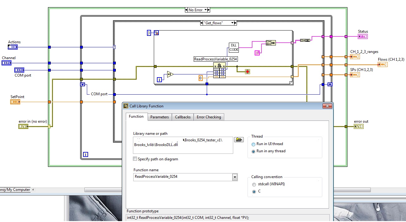
I decided to use the supplied DLL to control the MFC 3 through 0254 unit and also to read the flow, the PVs of MFC.
I did not provide examples of LabVIEW (plenty of flat sequence structures, too crowded, etc.), but he gave a good idea how to call the DLL, what settings should I use.
I implemented a LVLIB including the DLL, a public private Action and subVIs engine for these tasks I need for my experience. Next, I made a main VI only to the objective test, I'll run this VI now for several days to see the stability of the communication, etc... I don't have gas connected to flow regulators, so now, I have only test the communication... So far so good. I have attached the zipped project, including the driver of the lvlib and the criterion VI (it is a VI test, I know that it's not too pretty
).My experiences so far:
- To read the actual flow of the values of the 3 MFC takes about 1.5 to 1.6 seconds, so I'll use just a 2 sec of sampling time for DAQ in my actual project (in a separate loop, do not disturb/slow down my cDAQ sampling)
- When I started to first test of 0254 unit, my GUI became incredibly unresponsive! I took a look at the configuration of the DLL and managed to solve this problem of GUI lag by setting the thread DLL to "any thread" instead of using the user interface of one.
- If I get later the real flow tests made without problems, I will consider the product as usable. So far, it seems that it will work, fingers crossed
Martins wrote:
rolfk, the llb seems very pro (calculation of checksum is also necessary that I see)! Thanks, I will test it just today, in fact, these are all the features I need: read flow values misses three Brooks MFC and change their values...
I have two questions to your code regarding:
- I see there is an entry "address." Why is it an option (by default, it is not used in your code) in the llb? I thought that this device can only be used with RS232 and RS485 (so no multiple devices in a wreath, so an address would be wise)? Sorry, I read now on the address, it is clear now.
- I wonder about the reason for the digital manipulation of the value of the incoming channel:
- In the Subvi set point, you double the value of channel number
- In the Subvi flow Get value, you double the value and the Decremenet with 1. Why?
Point 1: I only use the address entered in my configuration, but decided to apply in all cases, as it has been documented in the manual. More likely one would need to add it to the Initialize function, the Identification query command. These units can be apparently used in a multidrop facility where they are chained in some respects. Because the client has already had two RS-232 over Ethernet to RS-232 hub ports, he wouldn't try to implement in this way and in further trouble with the wiring and units, such as multi-point communication debugging usually always committed.
Point2: If you read the manual it somewhere says that the channel to read a value from a physical channel must be odd, then to write it must be the same. Do not know what is the logic behind this, but it makes sure the analysis on the side of the camera probably easier that you don't have to look for a leak? to a query or a xxxx = nnnnn.ddddd to update a value but simply to take the channel number to decide if you need to read or write. Ultimately any implementation can be considered to be logic, as long as it works.

Basically the channel to use in the command turns as double the physical channel for the Scriptures and a number less for reads.
As Ben mentioned problems, I had some problems initially with this camera and it could actually be someone from the distributor of Brooks here in the Netherlands that has done something with the units (perhaps an upgrade of the firmware) but it was still a few years ago, and my memory about the details is rather blurred now.
We also examined him to speak the MFC Brooks via their RS-485 interface directly without going through the unit 0254, but which was abandoned subsequently especially because the client had already in another that uses the 0254 and wanted a display to check and manually manipulate the MFC from a software failure. These lab people simply want to have physical buttons to push to feel safe.
Whatever the 0254 navigation menu is a little tricky to operate.
Maybe you are looking for
-
good will I be completely blind here? in logic 9 there is a super editor who allowed me to create a rise with the ground effect. It's a great tool... but I can't find it in logic pro x? have they got rid of him! can anyone help
-
Satellite M40-145: Portuguese and European models are different?
We bought 2 M40-145 and 2 Port Replicator III. These products are also compatible to the European and Portuguese Toshiba site. However, it seems that they are not. Can you confirm this? Is it possible that there are errors in the site? Thank you José
-
Presentation of screen advice needed
I am trying to build a number of presentations that will extend over several screens (at least three), each with their own content (not mirrored). I looked into a calibration screen (Matrox) solution and it may work, but as we'll probably to 4 k vide
-
internet radio - sounds Chipmunks singing songs - the conversation about the games or video is sharp loud
-
Receive errors don't respondents not