LineChart - create onMouseClickEvent the symbol of the graph
HelloIs it possible to define an onMouseClickEvent on the symbols of a line chart? My sample code below works on the lc together, but not symbols.
 lc.setOnMouseClicked(new EventHandler<MouseEvent>(){
    @Override public void handle(MouseEvent arg0) {
     System.out.println("Clicked on the chart");
    }
});
    for (XYChart.Series series : chart.getData()) {
      for (final XYChart.Data data : series.getData()) {
        data.getNode().setOnMouseClicked(new EventHandler() {

          @Override
          public void handle(MouseEvent event) {
            System.out.println("Clicked on " + data);
          }
        });
      }
    }
DB
Tags: Java
Similar Questions
-
Create a button to erase/reset the data displayed in the graph
Hello
I'm new here and to work with labview. I searched the Forum but have not found an answer that would help me (or at least I think I thank)
I'm working on a project to acquire process an ECG signal with an acquisition of data. In the front panel, I am trying to display 2 graphics, part of the real-time data display and the other showing all the data acquired up to now. I wanted to add a button to this second graph that, when the user wanted, deleted the data shown in the graph, but immediately continued to display the data.
(trying to make me more clear)
' display all the data acquired--> X--> cleans graphic display--> press the button display all acquired data.
If someone could help, I would be very grateful!
Thank you very much
FM
Hi fred,.
Open the finder example in LabVIEW and locate the example of 'how clear diagrams & graphics '.
Pretty easy, don't you think?
-
Can charting CF - I make positive negative labels in the graph horizontal bar?
I use ColdFusion 7 on solaris 8.
I'm creating a tornado with a horizontal bar graph chart to display two sets of accurate, except cards
series is to the left of 0 and a series is to the right of the zero and each series is stacked along the same line.
Can I do the label values negative axis on the left side of the show of the axes of the graph in the form of positive values label?
This is a very rustic representation of what the table looks like:
* * * * * | (- 5 to + 5 to the right, left)
* * * | (- 3 left, 3 right)
* * | * (- 2 left, 2 right)
* | *
-----------
-5-3 0 3 5
I want the table to stay as is, but have the bottom label to show that:
5 3 0 3 5 (essentially removing the "-" sign on the left side of the labels 0)
Well, thanks for any help anyone can provide!
* Here is a snippet of code for the chart:
< seriesplacement cfchart = 'stacked' chartwidth = "350" chartheight = "200" showlegend = 'no '.
scaleFrom, scaleto = '-5 "= style="./hzBarStyle.xml '5' "fontbold = 'Yes' format ="png">< cfchartseries type = "horizontalbar" > <!-left-side bars on the graph of tornado >
< cfloop query = "getReportVals" >
< cfset dataVal = - #round ((getReportVals.score/score_total) * 100) / 2 > <!-Note: sign-less >
< point cfchartdata value = "Point #dataVal #." = #dataVal # >
< / cfloop >
< / cfchartseries >< cfchartseries type = "horizontalbar" > <! - good sidebars of the tornado chart - >
< cfloop query = "getReportVals" >
< cfset dataVal = #round ((getReportVals.score/score_total) * 100) / 2 > <!-Note: no less-> signs
< point cfchartdata value = "Point #dataVal #." = #dataVal # >
< / cfloop >
< / cfchartseries >< / cfchart >
* Here's the style developed using WebCharts Ent file. Edition v5.0h:
hzBarStyle.xml
******************
<? XML version = "1.0" encoding = "UTF-8"? >
< frameChart is3D = "false" >< xDepth = '6' yDepth plan '6' = frame = "#000000" lightColor = 'white '.
leftAxisPlacement = rightAxisPlacement 'Front' = stripColor 'Front' = "#FFFFFF" >
< background minColor = "#999999" / >
< / framework >< dataLabels style = foreground "Pattern" 'white' = >
< / dataLabels >< elements place = 'Stacked' form = contour "Column" = "black" >
< morph morph = 'none' stage = "none" / >< index collection = "0" >
< paint color = "#0000FF" / >
< dataLabel >
<! [CDATA [$(colLabel)]] >
< / dataLabel >
< / series >< index collection = "1" >
< paint color = "#0000FF" / >
< dataLabel >
<! [CDATA [\t]] >
< / dataLabel >
< / series >\n\nTotal $(colLabel) value: <! [CDATA [$(rowTotal)]] >
< / items >
< isVisible xAxis = "true" >
< labelFormat pattern = "#, # 0" ###" / >
< parseFormat pattern = "#, # 0" ###" / >
< labelStyle orientation = "Vertical" color = "white" / >
< titleStyle foreground 'black' = > criteria for data < / titleStyle >
< / xAxis >< foreground popup = '#000000"background ="#FFFFFF"/ >
< legend >
< style decoration = "RoundShadow" / >
< / legend >< title >
< style decoration = "None" / > Tornado Chart
< /title >< paint = "Plain" / >
< / frameChart >
The display is controlled by a ground impossible.
That is to say "positive format; negative format.
Unfortunately, the javadocs say positive and negative models must be different or the negative trend will be ignored. Probably the best you can do is to replace the '-' with another symbol. A space character * might * work
.. If not, you may need to use some other character as '+' or ' * '.
Just be sure to apply the format to the correct axis.
Post edited by: == cfSearching == -.
-
How to use the graph of the intensity in the iPad data dashboard.
Hello
I use a graph of intensity in my vi main under a project of myRIO.
I created a shared variable of the 2D array. When I selected the variable in the ipad it does not show that he presents in the pc...
I want to mention that I have selected the multiplier as (= 30/255) 0.117647 in labview in pc
I use the version of labview 2015 myRIO.
and I am using iOS 10 in my iPad
can someone help me please
Hi adil,.
The graph of the intensity is not supported in the dashboard of data.
Kind regards
Denny
AE Singapore
-
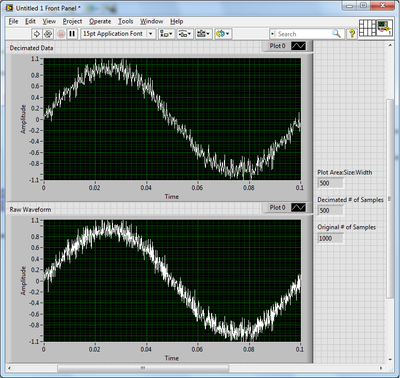
How the graph data are resampled pixels?
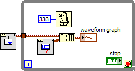
A test, I created two identical graphs with land areas 500 pixels wide and a noisy sinusoidal signal of 1000 samples. A chart displays the waveform right, while the other got the results of the use of the function Arrray to decimate to halve the number of samples. They are not the same.
Up to a waveform graph does exactly when it displays a data value larger than its width in pixels?
As you have noticed, the graph is a little more intelligent that you expected. When the number of points exceeds the number of pixels, a form any resampling must take place. A simple decimation as you tried would eventually pass some interesting points. Instead, the outliers receive priority when selecting which points to display. Strong in this way, peaks and dips appear even on a large scale. Reproduce this behavior yourself can be tricky. And once you reduce the data set, the points are gone and zoom is not as effective.
Usually, I try to let the chart to do as much as possible. A simple and effective way to reduce the size of the data you have to ship on the network is to use the SGL precision instead of double precision.
-
Hi, I have two decimal strings, each of them contains the numbers change over time. I want to plot them on the graph XY, a string for each axis. Can you show me how do?
This is not a formula, but a constant simple schema of a table complex. Wire remains, then do a right click of the terminal of the initializer of the feedback node and select "create constant. That should do it.

-
How to set the properties of the graph XY via VI Scripting plots
Hello
Is there a way to change the properties of the graph XY plots in a VI script?
Main VI, I create an XY chart in another VI in a VI script. Now, I want to change caption of the field names and their styles etc. I notice that these properties can be implemented in the new VI (see screenshot graph Node in NEW VI.jpg property). However, I could not see these properties by calling the property node of graphical reference XY main VI (see screenshot).
Thanks for the reply due.
Concerning
HB
Hello, HB,.
Maybe you need to use a XYGraph refnum rather than a refnum graphChart.
ULI
-
How to ensure that the graph xy plots are present?
Hello community,
Since the update to LabVIEW 2014 this week, I have a problem with the code that worked (or didn't, but the problem was unnoticable).
As example the llb I created to present the question, I'm graphic xy filling with quiete some data and then color programmatically plots.
The problem is that if there are too many plots then the property nodes that are to color the mistakes of Mr. thow plots as if the corresponding plots were not present in the graph still - even if I used a single flat sequence structure to try to ensure that the data is written in the plot before trying their color.
Maybe this wouldn't be in LabVIEW 2013 too - but the threshold for the number of plots was higher. All I can say is that I have observed this with data sets that worked well in 2013 of LabVIEW.
To reproduce simply run 'color of the graphs.vi' with values high enough to 'numerisch' and ' numerisch 2 "(50 on my machine can be more about yours).» I left the terminal nodes property unwired error so you get caught up in the right position when the error occurs.

Somehow check if all parcels are in the charts again? This way I could introduce a delay that ensures that I don't have the color of the graphics that do not exist yet - regardless of the speed of the target computer.
Xy graph behavior has changed in 2014 of LabVIEW? Or maybe his performance?
Best regards
Florian
HM, your addendum somehow answered my question. We are indeed an against the user interface thread race condition.
Unfortunately, I do not know a method to wait than the UI thread to have access to all plots. In addition, the waiting time that you need depends on the ability of the system, which is dynamic, you know not all processes background or in parallel, running applications.
That being said, I recommend a work around:
1. create the data for the plots
2. how many plots you have in query data
3 write short dummy data in the terminal, and not the data of the whole plot
4 Recolor plots
5. write the correct field data
Norbert
-
dispplaying data on the graph of waveform inside/outside while loop
I create a vi using the random number generator, entering the number in the function(express>>arithmateic>>maths>>trig>>sine) fishing and connect the output of the function sine waveforms. Table of waveform show no problem. If I replace the with graphic waveform table, I get an error that the source type is differenct type of sink. I then put waveform chart outside loop everything hoping that tunnel would act as a table, but still I get the same error. I then put build table palette between all border and loop waveform graph which is placed outside the while loop. I get no error, but no data is displayed on the graph of a waveform. Theoretically, if I press stop I would see a distorted sine wave on the waveform graph, but this doesn't seem to be the case. I am wondering how to view data on the graph of a waveform in such cases!
Thank you in advance for reading and help!
See you soon
First of all, you can take a part of the basis of LabVIEW tutorials.
Since you need to work with a chart and it is the preferred method to display data point by point, I don't know why you try to use a chart. In any case, you cannot use all simply a table of generation because that would be just the result of the last iteration and your graph indicates it is a single point. If you activate autoindexing, then you get all the values, but not before the end of the loop. If you were to use a shift register and the build dashboard, you might place the graphic inside the loop, but then you would face performance issues that the table would grow uncontrollably.
-
How can I specify pixels in the graph of the intensity?
Hello
I want to specify the number of pixels in the in the intensity chart. I have 56 values want to display. How can I do this?
Hi jerryvdk,
By specifying the number of Pixels, you hear, allowing only a specific land area size of the chart itself?
You can change this through the use of a property node.
Steps to change the plot area size:
- Right-click on the graph of the intensities.
- "" "" Scroll create "property Node" plot area "size" all items.
- This will create a property node that will allow you to change the property of area of the draw of the intensity card.
By specifying a space of draw of the 56 x 1, this would allow a 56px draw area size fate. Is that what you meant?
-
Plot the graph of origin using Labview
Hellou,
I try to plot the graph of origin using Labview. In Labview I connect and create the new model of origin for instance. Template file (.) OPJ) was created before. End of data in the worksheet then I plot the graph of origin. But I can't use OA_NewEmptyGraph.vi because it is to create a new chart. I'm trying to graph in graph model.
In labview that I found for OA_FindWorksheet.vi sheets, it's journal to find, but a cant find, a few "OA_FindGraph.vi" is - it is or made elsewhere?
Thank you
Norbert
Hi Norbert,.
your question seems to be linked to LabVIEW, while you're wrong he posted in the forum of LabWindows/CVI.
-
I want my table to have a constant slope already mapped out before she continues start tracing data in real-time... so that I can compare my new data point to point with the ideal slope that I already have in the background
Hi raza,.
as I said: it is not a problem to have two plots on a graph. But you need to use a graphic instead of a chart!
Like this:
have a constant ground created before the loop and a variable field created in the loop!
-
Change the graph with nodes of property
I've been struggling with this problem for a while now. I have a graph of simple waveform I want to set the horizontal scale to and then make a .png to file. The vi is attached. This vi is up to a lot more great vi. Does not work when I run the first level vi of the adjustment of the horizontal scale. The .png file I receive shows the unadjusted graph. However, if I open this vi and then run the first level vi it works - the graph shows the .png file scale properly. Also, if I just run this vi se it works correctly.
I'm guessing there is a timing issue and the .png file is created before the scaling takes place, but I don't see how.
Does anyone have any ideas as to why the scale does not if the vi is not open, when it is executed?
If the front of the VI is not open, the nodes property can do nothing because they run in the UI thread. This is consistent with the behavior you report with it works when the VI is open.
Can you try to open the façade but putting off the screen (if the user does not see it) and then set the properties of the graph?
Lynn
-
How to draw the graph of output?
Hello
How to draw the graph of an exit? is there any api for it?
The short answer is that there is no API, but you can create your own field if you want to, and here are some samples:
http://supportforums.BlackBerry.com/T5/Java-development/create-graph-fields/Ta-p/444968
I recommend the search before you ask questions to see if other people have asked similar questions. If you type chart in the search box you will find other similar topics.
-
BI Publisher 11: decrease the resistance of the graph in the designer
Hello
We use Oracle BI Publisher 11.1.1.7.150120 (build # 20150113.1211 kill him Jan 13 12:15:48 THIS 2015)
can you tell me please how to decrease the hardness of the graph in the designer of BI, I enclose a sample Charter.
Best regards
Djam

I create an SR, and the solution is:
This is done via the property table:
With the layout template open in edit mode, expand the 'Properties' of the left frame section.
-Select the first 4 charts
-then Properties section expand the "graphic plot area.
-Select 'Series 1 line width' and enter the value 1 px
-Select 'Series 2 line width' and enter the value 1 px
-Select 'Series 3 line width' and enter the value 1 px
Djam

Maybe you are looking for
-
Hello Since a few days, it takes more than 30 to 60 minutes to open Firefox on my laptop. I'm on Vista and have Anti Virus. I already tried to reset firefox, uninstalled and installed again. My version of firefox is 29. But nothing seems to help. Can
-
Is there any way to install the operating system and drivers without recovery CD?
Hello... I installed my laptop with the recovery cd...but I disappointed because he installed many unusual programs like sonic-pro games, aol...What is a way to install windows and drivers only? without this annoying programs? I don't want to uninsta
-
Construction of an RGB Image using IMAQ ReplaceColorPlane VI
Hello world I'm trying to familiarize myself with the Vision Development Module on LabView student edition of 2009 because I want to manipulate images in real time. Currently, I am trying to split an image RGB in R, G, and B pixel values then recombi
-
By using the Date/Time Format String function Vi
I wanted to display the time in milliseconds to Labview and I got it to work. I want to display AM or PM after the milliseconds so it looks like this 31/05/11 4:45:39.849 PM I use %p as you can see from the picture, but it does not work. AM or PM doe
-
HP Phoenix h9 - 1110t Windows 8 bios upgrade available but where?
By HP links. http://h30434.www3.HP.com/T5/desktop-operating-systems-software-recovery/HP-PCs-basic-input-output-S... https://h20564.www2.HP.com/hpsc/doc/public/display?docid=emr_na-c04393276 According to these 2 links. An update is available for my P