linking to toolkit modulation AM function generator
Dear
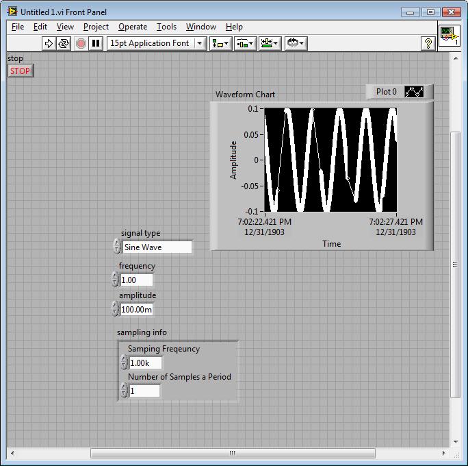
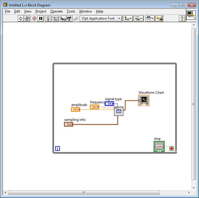
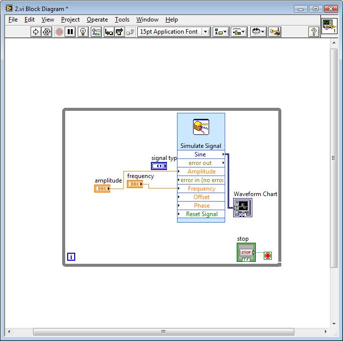
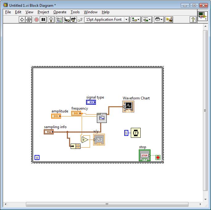
I am doing a project in telecom AM modulation demodulation using labview.
I have attached, the function (such as message signal) generator and modulate Am (as a process of modulation AM) but I am facing problem wiring the function as the message signal generator in the AM modulation. I would be grateful if someone can help me that doing so. In addition, if you have an idea how to make the process of demodulation using the MT modulation toolkit I will be grateful.
Thank you for your help
Hi Sir... Peter,
Thank you for your, you helped me a lot in the resolution of many problems in my project.
I still need your help for something;
I did the AM modulation as you fixed, and I added the demodulator block in order to recover the original signal from the message.
In fact, I am facing two problems:
1. in the SSB: single side band, I'm not able to recover or demodulate the square wave type.
2. I am not able to modulate and demodulate a file audio wave.
I would be grateful if you can help me in carrying out my project.
Thank you
Tags: NI Software
Similar Questions
-
Open link in a new tab function when Middle-click there just disappeared.
Hello! Open link in a new tab function when Middle-click there just disappeared; now, when I Middle - click on the link, nothing happens - no new tab, just nothing! It comes not with a mouse, I tried another mouse and it's average click and even in other browsers works; Right click and 'Open link in a new tab' (as well as other options menu) to work correctly. No idea what happened? Thank you!
You can have an add-on which interferes with middle-click behavior. To test this try the procedure described in article Troubleshooting extensions, themes and problems of hardware acceleration to resolve common Firefox problems .
-
Digital output frequency seems to be twice the frequency generated by the basic function generator
Hi Labview forum,
I wrote a program (attached) Labview to generate 3 PWM, square wave, signals that has the same frequency and phase delay right (so that when a signal is off, the other signal is lit. Then the next signal). Everything seems to work fine except that the frequency of the PWM signals generated seems twice as the frequency given to the basic function generator. Anyone have any idea why this is happening? Anyhelp would be greatly appreciated.
Thank you!
Totally agree with the advice of all GerdW than the hardware timing of your hardware DAQ will be much more reliable. That said, part of what you are probably hitting is a little quirk of the primitive delay msec. Requests for 1 msec have long been particularly little reliable (although they * seem * to have improved in recent years, probably due to the better OS support in Win 7 or something).
I did minimal mods to your code with comments from you switch to a timed loop. My quick test showed he is good enough to hit the 1 length of loop of target msec.
-Kevin P
-
function generator (HP 33120) running to the superior at 1 kHz by Labview
Hi all
To run a function HP 33120 Labview generator, I downloaded a driver "Agilent 33XXX Series", also attached to this message. But the files of vi (for example 'Waveform.vi Standard' or "Arbitrary Waveform.vi") available in this driver, do not allow the function generator generations a more signal of 1 kHz, while I need about 200 kHz. Manually the function generator can easily generate a signal to 15 MHz.
So I need a pilot/vi of this function generator that can generate a signal to about 200 kHz. Kindly help me.
Thanks in advance
Concerning
Fadi
Dear Dennis
I think I had hardware problem where I was able to change the frequency of 1000 Hz and 999Hz and so one but I was unable to move from 1000 Hz to 1001hz and so on. But now it is resolved.
Thanks again
-
Need to model for the XR-2206 function generator chip
I'm designing a training tool for the operation of the basic oscilloscope and decided to use a function generator based on chip XR-2206. Is there a template for this? I know its old but...
Hi jwaters,.
Unfortunately, we do not have anything; However, perhaps it will be useful.
-
Hello
We have a generator function SRS DS345.
I just downloaded the driver NOR for the instrument on http://sine.ni.com/apps/utf8/niid_web_display.download_page?p_id_guid=E3B19B3E9149659CE034080020E748....
After installation, the DS345 appears in MAX, and I can well communicate with him.
However, if I run the srds345 to Started.vi, I get an error "location information insufficient (Hex 0xBFFF0011) or the device or resource is not present in the system" from initialize it with Options.vi srds345 sub - vi.
The only change I did Exchange address GPIB 14 to 19, which is our function generator GPIB address. In addition, the
Functions of SRS DS345 generator of function palette is empty, even after you restart LabVIEW (see attachment). I'm using LabVIEW 8.5.1.
Your help in resolving this issue is appreciated. Thank you.
Best regards
Peter
Have you installed the driver from LabVIEW or copied directly from inst.lib?
The first is easier, and you don't have to restart LV more...
Error in a not filled gpib address points. I have not checked if this driver has a resource name visa or a string of gpib address old but in the first case, try the little triangle on the right at the slect address instead of by hand.
-
Continuity of the functions of the basic function generator
I would use the basic function generator to create a continuous waveform.
im not sure if Im not run or use the function generator correctly.
for each iternation of the while loop, I would like to only one point of the exit sinusoid.
Then the next iternation would produce the next point in the sinwave.
It seems to keep missing a few points
I'm not sure why - this.
It's hard to notice that if the plot is made only show few places for each sampling point.
I'm fairly certain that that VI uses the current timestamp as the value of x, so whenever your computer receives a bit busy (I'm off / 0, etc.) it is likely to be a small problem. You can always use the simple sinus with the number of the iteration (optimized for the desired period).
-
Continuity of the functions of the basic function generator and the right time
I need to create a sine wave, point by point, which will be forwarded to the MIP and finally to a channel of analog output on a PCI-6014
Ive tried a few different ways to do it, but everyone has some problems with her slider.
with the 'generator.vi of the base feature.
and also the "sine waveform.vi.
There seems to be problems with this lack of points.
someone helpfully pointed, its very likely windows interrupts the origin of the problem
Here is a schematic representation of the panels front and rear
the back panel
the façade has a few points that are missing
Another way to do that seems to work better known that the signal "simulate" express vi.
It's great because it's actually a way of sine 1htz occur at 1htz.
There are also all the points.
The problem is that as soon as I put in my request, she grinds to stop.
Program speed about changes 10khtz less than 1htz when the basic function generator is replaced with this express vi.
A third idea or concept that has been proposed is to put a programmer to slow the timetable.
It is once again, works fine, no more points are missed in the plot.
Yet, he kills again the speed of execution of the program as everything can wait 1ms (or the recripocal of sampling points interval time).
Someone at - it an idea on how I can get a sine wave in PID, then, in the analog waveform without a huge amount of the efficiency of the program. Im sure this is simple.
Nevermind
accedanta do the 2nd option from the top.
go just to increase the number of samples for now leave the rest of the fastest of the program
-
Lack of first samples using digitizer Tclk and function generator
Hello
I have a pxi-5922, an arbitrary signal 5412 generator. They are synchronized due the Tclk. The question I have is that I can not capture the start of production of function generators. I tried the positions of different reference for the scope, but am unable to quarter at the beginning.
I tried to have the function generator and digitizer as the master, this does not seem to help with my question.
Is there something else I could try to capture the start of the release of gen func using Tclk.
See you soon,.
Brett
So the 5922 has a delta sigma converter that will cause a delay of the sample during synchronization with other cards, the same as our DSA cards. It is the delay of the sample we see and has nothing of synchronizy we can do to get rid of him. What I would recommend is to generate samples 62 "junk" at the beginning of your waveform.
-
#VALUE in Excel for a formula that uses a missing cell with the function generator
Forum,
When I use the function generator to retrieve data of HFM in Excel, I have a problem with the formulas using these data when it is absent.
If I didn't put in the #nodata / replacement of labels missing, then SmartView puts ' "in the cell, which causes an error if I try to summarize with something else (= '" + 1,234.56 returns #VALUE).
SmartView let me use me replacement value of 0... I have found a workaround using of.0 as the replacement value, but I guess there is probably a more elegant way to solve this problem.
Let me know if you have an idea.
Thank you
JulienHave you tried #NumericZero?
-
installation of the toolkit Modulation
Hello
I try to install the Modulation (MT) V4.0 for LV 8.6.1 Toolkit and I'm running the questions with the palette menu. The palette of digital modulation menu does not appear after installation (and not under addons or pallets of rf communication). VI Physics for digital modulation functions are located in the folder program files, but they do not appear in the menu of the palette of LV. Also, when I try to open the files of ments, Labview application lacks Subvi so I'm starting to think that something is really messed up with the installation of the Toolbox.
For the background, I'm running LV 8.6.1 PDS with measures spectral toolkit (SMT) also installed V2.4. I uninstalled, deleted and reinstalled the SMT and MT directories several times but I still can't the palette menu or the digital modulation VI to work properly. Also, I uninstalled all previous versions of Labview to check that there is no conflict version of Labview. Has anyone else encountered this problem with the modulation toolkit and you know a fix? I would prefer not to have to reinstall all Labview 8.6.1 but if that proves to be the easiest option then I guess I have no choice.
Thank you
Tim S.
Hi Tim,.
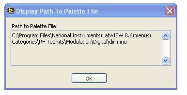
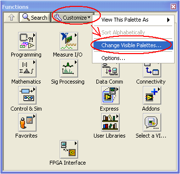
It seems that everything has been installed correctly, so I don't know exactly why this is a not complete automatically. I think we should try to manually add to the palette. I have included a link below that describes this process in more detail, you want to reference part "V. or pallets missing icons. You want to add the digital section to the palette by pointing to the file correct .mnu located in the digital file. I've included a picture where my .mnu as reference file. This should work for you, but please post back and let us know how it goes or if you have any questions.
Missing icons on the functions or controls in LabVIEW Palette
http://digital.NI.com/public.nsf/allkb/46E1672AB48C917D86256AFE00075436?OpenDocument
-
I can't find any plugin search google for firefox 4, Ask and Bing are the default.
Install this module: https://addons.mozilla.org/en-US/firefox/addon/add-to-search-bar/
Then right-click in any search field and choose "Add to search bar."
Uninstall Ask.com if via modules | Because extensions which it seeks only results with paid advertisers.
Alternatively, you can go back to Google as default search engine as follows.
- In the address bar, type Subject: config and press ENTER.
- In the filter at the top, type: keyword. URL
- Double click top and delete everything in it and replace it with http://www.google.com/search?q=
The URL to add in "keyword. URL"becomes a link in this message, right-click and choose"Copy link location"to copy it to the Windows Clipboard. Then press CTRL + V to paste. You have to type all of this saves.
To reset your home page, follow these steps.
- Go to the site you want to set as your home page.
- Click on the orange button Firefox and go to Options | Options | General (Firefox 4.0.x and above).
- Go to Tools | Options | General (The previous version of Firefox).
- Make sure that it says in the first drop 'show my home page'.
- Click on the button called "use current Pages' to set the home page to the one you have on the screen.
After completing the steps above, install this add-on to prevent another search engine to change your preferences: https://addons.mozilla.org/en-US/firefox/addon/browserprotect/
-
NEITHER USB 6343 negative DC voltage after power function generator
Hey all,.
I'm having a problem with my DAQ. I'll generate a square wave in Labview with a generator function and that the output to my DAQ. The function exited through the acquisition of data very well; However, when the production is stopped, a negative voltage remains equal to the amplitude ("drawing" below). This happens if I use the express VI DAQAssistant, or manually create the channel, generate the function and the function read/write on the channel. This tension continues even after the VI is finished running. The only way to get rid of it is physically cut the DAQ and turn it back on. Any thoughts on why this might be, or how to fix?
Start VI
____|____|____|____|____|____|
____|____|____|____|____|____| _ _ _ _ _ _ _ _ 0V
____|____|____|____|____|____|____________ - A V
____|____|____|____|____|____|
End VI
Tom
I thought about it. I had to add some more to the clock. I had added a data point in the table of waveform which was written for the acquisition of data because the timer wrote n samples, instead of n + 1

So, to recap: I pulled the table leave the waveform data, inserted a '0' at the end of the wave, reintroduced the data of Y in the form of wave and incremented to the timer of a sample (because I added a sample for waveform data).
-
Declaration of invalid function generating a range of service
Greetings-
I am trying to create an instrument in 2013 CVI driver. My successfully the DLL builds, I then open my header with my export file and select options-> generates a function tree. All my statements of functions return with "invalid function for
statement. I can't focus your web searches to shrink in generation of functions and the error Panel. So I submit to you my problem. Below is my header file...
#include "Simulator.h".
#include "visa.h".
#include "vpptype.h".#if! defined SIM_INCL
#define SIM_INCL#define DEFAULT_BUFF_SIZE 512
ERROR SETS
#define SIM_CONFIG_ERR-1001
#define SIM_CONFIG_TIMO-1002
#define SIM_CONFIG_BAUD-1003
#define SIM_CONFIG_DATA_BITS-1004
#define SIM_CONFIG_PARITY-1005
#define SIM_CONFIG_STOPBITS-1006
#define SIM_CONFIG_TERM_CHAR-1007
#define SIM_CONFIG_INIT-1008#endif
enum PRNDL_State {PARK = 0, REVERSE, NEUTRAL, DRIVE, LOW};
FLOWCONTROL MEASURE
typedef enum _flowcontrol
{
NO = 0.
XON_XOFF,
MATERIAL
} FLOWCONTROL;PARITY OF UNINSTALLATION
typedef enum _parity
{
NOPARITY = 0,
ODD,
SAME,
MARK,
SPACE
} PARITY;MEASURE COMPORT_SETTINGS
typedef struct _comport_settings
{
int baud_rate;
int DataBits.
PARITY parity;
StopBits double;
int portNum;
FLOWCONTROL flowcontrol;
char * ComName;} COMPORT_SETTINGS;
-> ConfigUtils
int __stdcall ConfigSimulator (ViSession DefaultRM, COMPORT_SETTINGS SimPort);
extern int __stdcall SimulatorSetInit (void);
extern int __stdcall CloseSimCom (void);
///<->-> SetterGetterFunc
extern int __stdcall SimulatorSetVBatt (int State);
extern int __stdcall SimulatorSetIgn (int State);
extern int __stdcall SimulatorSetAcc (int State);
extern int __stdcall SimulatorSetPrndl (int NewPosition); / * P = 0, R = 1, N = 2, D = 3, L = 4 * /.
extern int __stdcall TapUpDwn (int NewState); / * 0 = no no tap Tap Up Dwn * /.
extern int __stdcall derivator (void);
extern int __stdcall ReadVBATT_Status (void);
extern int __stdcall CallReadSimulator (void);
///<->Hello don,.
If you ViSession typedef in your head, it works. I think that the included headers are not checked.
You can set it as
typedef ViObject ViSession;
the same as in visatype.h
If you set different you should get an error to the compilation, it should be safe to redefine.
After you do this, remove extern specifier to other functions and generation fp must succeed.
Constantin
-
I have not found multisim connectivity toolkit in connectivity function palette.
I installed 'ni LABVIEW toolkit of multisim connectivity powered by beta', and then also I find in range of function of connectivity. I read above facts in the tutorial that is downloaded from the Web site of nor. The tutorial is attached.
Looking forward for your reply.
Thanking you
Best regards
Avinash
It is possible that the installation is successful, but you are unable to locate the function Palette API, OR there could be something wrong with the actual installation.
Well good to check if the Connectivity API Multisim are present:
-> To open a new black VI LabVIEW > navigate to the diagram and open the Palette of functions.
-> now press "space + Ctrl".
-> search for say "Multisim Connect.vi.
If the result of the research shows this VI so you can see exactly where its located on the hard disk (from dialog box properties of the VI) and location can also likely in the range of functions can be determined.
There is another possibility that any 'connectivity' palette is set as invisible. Even in this case, you should be able to search APIs Multisim help above the method.


Maybe you are looking for
-
Can save us our system drive on Dropbox?
Hello! As the title says, "can save us our system drive on Dropbox? Thank you!
-
Discuss things Apple in iMessage group chat?
Hey guys is there any group assets iMessage chatty? Just to discuss things apple. Nevertheless. If not, can we exchange our IDs iMessage and start a? RAM
-
THIS MESSAGE APPEARS SEVERAL TIMES AND RANDOM WAY AND CONTINUES IT SAYING WINDOWS WILL CLOSE THE PROGRAM. AND IF A SOLUTION IS FOUND - BUT THEY NEVER DO
-
Whenever I click on my icon my internet network no longer works
As in the title I'm saying that when I click on my network icon on the start menu, I lose my connection internet, im is still connected to my wireless network but the internet dies and im forced to go and restart my modem and wireless router. I have
-
How can I change my computer passwrod - NOT my Microsoftpassword?
My laptop is Windows 8, I put a password. I want to change it. When I try to change it, I get a screen on my Microsoft Word - not the computer. On my desk, I can change my password to the computer - but it's Windows 7. How can I change the computer p