logarithmic scale & autoscale
Hello
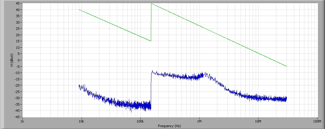
I use autoscale Optionconcernant X axis, which is logarithmic.
The problem is that the autoscale really does not work as it begins instead of 9 k 1 k, and ends at 100 M instead of 30 M (of the measure). How can I avoid the autoscale to do this?
Thank you
Hey J.D.
If you right-click on the graphic and select X-Scale (scale or Y) and deselect loose fit, that can help.
See you soon
Ian
Tags: NI Software
Similar Questions
-
Anychart question type logarithmic - scale starts at 1 instead of 0
Hello
I'm having a small problem with Anychart in Apex 4.2.4. I've included a picture below.
The question is when I put the type of logarithmic scale, the base value starts at 1. This means that you can not tell the difference between 0 and 1 without hovering above the value. I want the scale to start at 0. If I go back to the normal mode, it starts at 0, but because the size of the scale is constant, you can not see the difference between 0 and 1. I tried to add the attribute - minimum = "0" on the scale of the line and that didn't seem to do anything when the type is set to logarithmic.
Here is my line of xml to scale:
< base_value scale = "0" type = "Logarithmic" always_show_zero = "True" minimum = "0" auto_calculation_mode = 'Basic' mode = "Normal" / >
Here's what it looks like:

Two short bars in the 'All open' series have a value of 1 and the other is set to 0, but you can't tell by looking at it.
Any suggestions? I looked on the Anychart XML reference, and I feel that I must be missing something.
Thank you
Tim
Hi Tim,.
I think your best bet is to upgrade your XML custom to add parameters of scale for the value axis labels. Certainly, tt is not the link easier to locate in the AnyChart documentation, but their article number in the form of the user's Guide can be useful in this case, specifically their example on 'values to help scaling with axis logarithmic'. Their code snippet uses the following XML:
{Value %} {numDecimals:3, scale: (1000)} (1000) (1000) | (k) (m) (b)} I hope this helps.
Kind regards
Hilary
-
too many digits in logarithmic scale
I thought that I had pointed out before - but couldn't find the post, or a known problem...
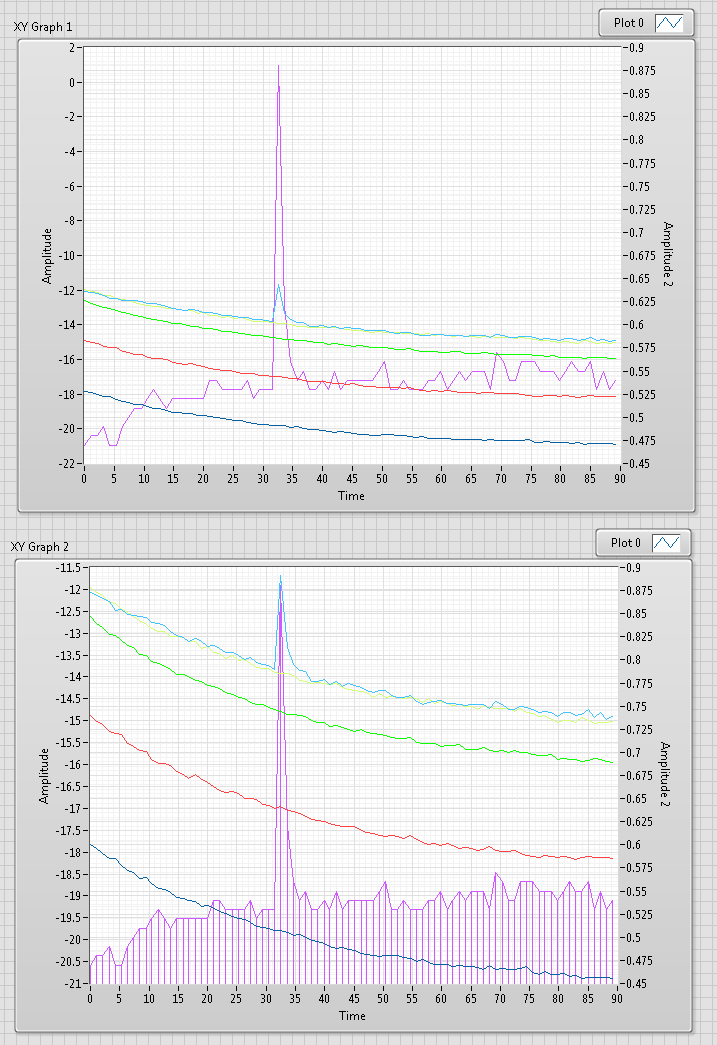
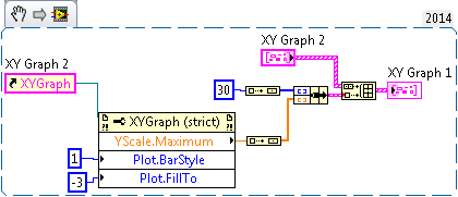
I have a non-sinusoidales XY plotted graph. Any fine. Then I change the scale Y lin connect and the disorder occurs, see below.
The left image shows the graphical border with a linear scale of Y, the right image after you change by program to save the scale
Hello Wolfgang,.
First of all, thank you for the provision of this demonstration and as always, thank you for your valuable comments. I created a bug report (ID: 438812) to follow up on this matter.
Thank you
Daniel
-
questions of small scale log values
I have a strange problems with tracing values in graphs for NI Measurement studio WPF. This problem occurs when the axis is log based on and the value on the axis spans less than 1 to 1 (i.e. 0.001 to 1000). The chart automatically change the lower x-axis to limit to 1. The behavior is similar to the one reported here (http://forums.ni.com/t5/Measurement-Studio-for-NET/log-scale-won-t-scale-to-show-small-values/m-p/27...) but in my case, none of the mapped value is 0 or less than the lower limit of 0 and the axis is set to greater than 0.
The code below will reproduce the problem:
Focus() pt = new Point [100];
for (int i = 1; i)<=>
{
PT [i-1] = new Point (0,1 * I, me)
}Field pl = new Plot ("test");
PL. data = pt;
Graph Plots.Add (pl);
Where the x-axis of the graph are log10 scale (and the boundaries are defined on {0,1, 10} in the code .xaml) and the y axis is linear (no matter the scale really). The chart automatically x-axis it 1 and this can be changed to 0.1 but it comes back again to 1 if the visible property of the chart changed.
This behavious doesn't happen if all the x-axis values are less than 1 or greater than 1 that is the code below to draw correctly and the axis is not reset to 1, etc.:
Focus() pt = new Point [100];
for (int i = 1; i)<=>
{
PT [i-1] = new Point (0.001 * I, me)
}Field pl = new Plot ("test");
PL. data = pt;
Graph Plots.Add (pl);
Someone knows it why it behaves like that and what can we do to fix this?
Which seems to be the case, it's that the default
FitLooselyrange adjustment see values ranging from 10-1 to 10-1, and then choose a range of0,10for data. Since no one can be represented on a logarithmic scale, forced the scale to an arbitrary value, less than ten years, thus giving a final range of1,10and truncating low values. I created a task to solve this problem.To work around the problem, you can change the
Adjusteron the scale to another value, such asFitExactly. -
Points in logarithmic time for Collection
I am trying to create a Subvi, which will send as a table 1 d of the equidistant points on a logarithmic scale for a vi greater than use to the time of data collection. That is why by collecting those moments the VI will effectively capture data as a semi log plot.
However, everything I'm doing is right for the Subvi to generate the table 1 d of points in time to integrate into my current program. I would like to be able to impose the number of points, the starting point and the end point. These constraints demand that the basis of the paper varies according to the initial settings.
If you use the equation
Number of points = x * Logx [end time] that I know to be true, you end up needing a productlog to use directly as a recipe math to generate the base to use to get the right number of points logarithmically spaced between two end imposed points. Is there a way to productlogs in labview or a vi already in existence of this problem?
Thanks for your help. I ended up doing in a roundabout way, but this is essentially a background variable for the journal which allows you to set the start and endpoints and many points between. I shared both positive and negative in order to avoid difficulties with negative logarithms. It is not super sleek, but I think it works.
I was talking about using the product log to work this formula, as I said earlier. However, I think that it is a roundabout way to do this.
-
Graph XY - linear scale data overlay / Journal
Hi people,
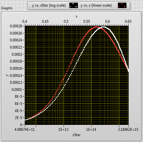
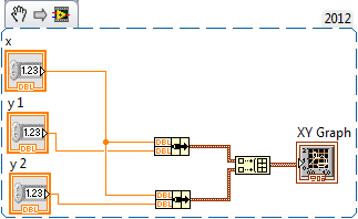
I'm in LabVIEW 2012 and I have a (x, y) dataset I want to draw on a set of dimensions. I also want to superimpose a second horizontal axis with the same data, but using a set of units on the scale (xStar). You can watch the enclosed screws to see how x transforms xStar, but it's basically the quadratic formula with an exponential lift. The x values are plotted on a linear scale, but because of this exponential transformation xStar-values are reported on a logarithmic scale (see image).
I want these two studs--(x,y) and (xStar, y)-to overlap exactly what they are actually a single parcel. That, in view of all (x, y) point, I can quickly raise the value of xStar glancing at the scale of the secondary axis. x and xStar are two useful physical parameters, then it is useful to be able to read one or the other on the chart depending on the situation.
Any suggestions on how to get these two plots overlap? Currently, I use the min/max-x values to generate appropriate min/max values xStar, which makes the plots suitable for endpoints (but not between the two). I also need to specify somehow scale increments? If so, what is a good method to achieve this?
Thank you!
The non-linear relationship (no log) is between x and xStar, you chose a logarithmic scale grid, so I guess that 'linear' scale must be adjusted.
Since the x-> xStar relatiion is given and fixed to a scale, you can create an image on the chart with the tools of photography.
read the newspaper scale min and max, read the pixel length x in the plot area and when the scale is changed (event) recalculate and pull scale "lin".
-draw minor ticks, draw the main graduations and numbers.
I would just use a scale, add a cursor block him to the plot and use changing the same cursor (read pointindex, get x, y data) to view xStar, x and y
I posted a vi accidentally in this old thread

-
Hello
I'm a little puzzled by the scale of my logarithmic scale...
Say that the range is-. 2 (or zero) to 17788.
(1) changing the mapping mode to log, I would have expected a mistake, according to the documentation:
Use a logarithmic scale for the chart axis. The minimum axis value must be greater than zero.
Obviously, he doesn't have to.
(2) having the autoscaled axis, the annotation is 18, with intermediate labels 100, 1000, 10000, and the largest label is 17788.
Why is the smallest label 18 and not 10, or 1 or 0.1?
I have Auto Divisions but no adjustment loose.
Thanks, Wolfgang
Hey Wolfgang,.
I realized after I posted that you mentioned you did not fit free in your first post, but thought that I had fun coming up with my next reply since you are in a different time zone. I see that I can't escape the vigilance of Wolfgang.
What was happened is that in this test, I changed to save the scale before tracing is not the problem you are having, if I understand correctly.
The problem is that, once you draw the data in linear mode, negative values are plotted on the graph. When you switch to log mode, we do not remove these negative values of the DataSet which causes the min autoscale to have an invalid value for the newspaper. In the case of an invalid value, we default to 1/1000 at least. If you were already in log mode and plot your data, then it correctly handles negative values for the newspaper and so they do not get considered for autoscaling.
When switching to record the scale, you should remove your current locations and replot them. This will allow the chart properly manage negative values for the trace log.
-
How can I get my card to bracts newspaper to zoom to get closer to an order of magnitude?
I have data may vary over several orders of magnitude and sometimes vary closely. To properly handle the former, I chose to use a logarithmic scale on the graph for these data. However, when the differences are subtle, the graph does not close any tighter than 1 order of magnitude.
Is there a way to get the next graph to connect automatically? I have certainly seen ticks for 3.5 * 10 ^ N, not just 1 * 10 ^ N-, but now they do not appear, let alone using them as the limits of the graphic.
I would rather not to follow the chart data in the program and property nodes allows you to change the scale by program myself!
Right-click... scale... uncheck "loose." Also affect autoscale.

-
Inconsistent behavior of the object Curve2DPreview with YAxisScalingType
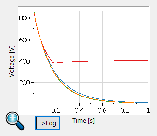
I'm trying to draw some curves tiara with VBScript. The only tool I found is the subject of "Curve2DPreview".
The curves are an exponential decay of voltage. When indicated on a linear scale, they look like this:
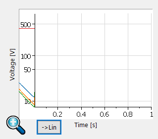
I put a button next to the plot to change the logarithmic scale, and when I do the result is the following:
Someone knows how to solve this problem and intrigue in the right position?
More information: I have DIAdem2015, the four curves are curves of waveform.
Thank you
Hi franco__,
You're right, that's not correct. The only workaround is to convert the string of waveform in an X / Y pair of channel and display this. I hope that we can fix the problem for the next version of DIAdem.
Greetings
Walter
-
Trying to insert 1 vertical line on xy-graph, but get more. Can someone give me a clue on what I did wrong?
Adding to my post: a point in this case is a pair of a x and a value of y
If you enter - Inf and + Inf for y values that you should always see a line (well, ignoring logarithmic scale
 )
) -
LogarithmBase10 does not properly
I have replace or WIN graphic graphical WPF.
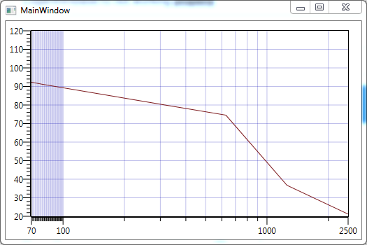
I'm using LogarithmBase10 in some graphics (you can see in the sample project).
When the range from 0, that's OK, but if I change the beach to another number (70
for example) the divisions do not display correctly [divisions are overcrowded].You can change the range and sometimes it is overcrowded and sometimes it's OK (depending on the number of departure).
I have to say: chart WIN, it is not the case.
First of all, just to clarify: by "WIN", you mean "Windows Forms?
I was able to reproduce the problem using your example. This seems to be a problem with how we generate divisions auto for logarithmic scales. To work around the problem, you can set the
Modeon theMinorDivisionsto the below custom implementation:public class CustomLogarithmicRangeDivisionsMode : RangeDivisionsMode {
protected override IListGetDivisionsCore ( IRangeDataMapper dataMapper, int divisionsEstimate ) {
return Auto.GetDivisions( dataMapper, divisionsEstimate );
}protected override IListGetSubdivisionsCore ( IRangeDataMapper dataMapper, IList dependentDivisions ) {
// (Note: this example assumes you supply the graph with "double" values)
const int LogarithmBase = 10;
double firstDivision = (double)(object)dependentDivisions[0];
double lastDivision = (double)(object)dependentDivisions[dependentDivisions.Count - 1];
double previousPower = Math.Pow( LogarithmBase, Math.Floor( Math.Log( firstDivision, LogarithmBase ) ) );var subdivisions = new List();
double division = previousPower;
while( division < lastdivision="" )="">
for( int i = 1; i < logarithmbase;="" ++i="" )="">
double subdivision = i * division;
subdivisions.Add( (TData)(object)subdivision );
}division *= LogarithmBase;
}return subdivisions;
}
} -
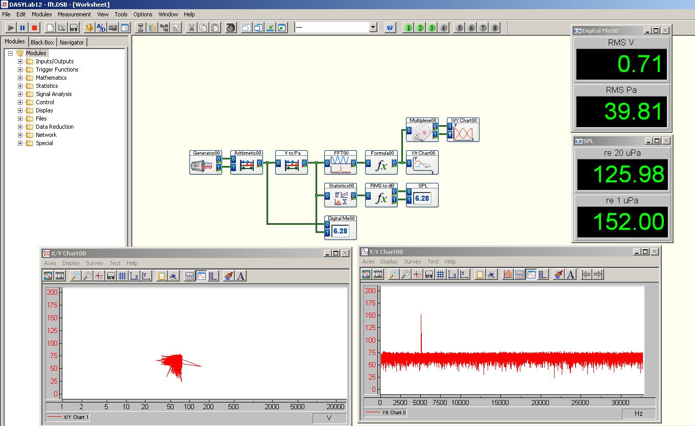
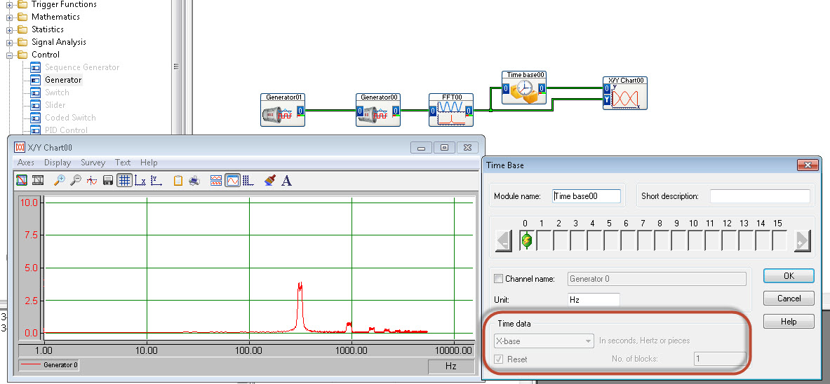
FFT to display with newspaper frequency axis
Hello
I'm trying to get my fft to display frequency (x axis) with a logarithmic scale.
There is no option for this in the table y/t
The xy graph has possibility of HRT, but I cannot "demux" the fft output signal successfully.
I use DasyLab 12.
Someone at - it ideas?
Thank you
Matt
Use the time Base module (special offer) to extract the x axis out of the block of the FFT.
-
NI USB - 6212 BNC analog input impedance matching
I just ordered a case NOR USB - 6212 BNC DAQ (should be delivered soon). I want to use to measure HV signals using a probe of high voltage of 1/1000 I have.
Now, datasheet of the probe (not a lot of info) says it has an impedance imput 100MOhm. I suppose that it consists of a simple resisitve divider, and if the ratio is 1/1000, I wait so to have a 99.9MOhm resistance in series with a 0.1MOhm resistance. However, the data sheet also specify that the probe is designed to be connected to an oscilloscope with an impedance of 1MOhm. As this input impedance is very low compared to the low value of the separator of resistance resistance, so I guess that the real resistance at the level of the sensor values 99.9MOhm and 0.11MOhm (to obtain the 0.99 and 0.1MOhm when it is connected to the oscilloscope for 1mW).
Therefore, given that the impedance of the USB-6212 according to the datasheet, the analog input is > 10GOhm, I expect to measure higher to true alternative voltages when connected to the acquisition of data from 10%. This assumption has a meaning?
What would be the best way to get around this? Do a calibration and correct the values acquired in LabVIEW code? Or should I add precision 1MOhm resistance at the same time to the acquisition of input data to decrease its resistance to entry to the value expected by the probe?
Thanks for your help!
Since you have a range of 1000: 1 I guess you also need bandwidth (I have a TEK 6015 A
), so you need based on the impedance input, a complex value, means he must not only watch but also the ability to input resistance (1 M). demarcation of the field probes have usually some elements of toppings to match the probe and the input scope. RTFM of the help of the probeBUT a more serious point is that with your probe, you have a very high resistance. And if you look in the specification of the 6212 you will find on page 2 by mistake ppm in logarithmic scale graph! and even 100 k source impedance it not shown.
So I'm afraid that a simple 1 M on the DAQ entry can work if you're only measuring DC, and only if you use a channel on the acquisition of data. A workaround is an amplifier separate buffer with an impedance of good entry corresponding to the specification of your probe and a low output impedance.
-
3D surface plot of updates and customization
Hi all
I use a lot of 3D surface to display a set of data over time, frequency and amplitude as x, y and z axes. I have a few general comments and questions about the use of this plot, I hope to get answers to
1. is it possible to remove part of the plot? The framework to display 3D land surface is in the default "modern" style. In 'user defined' view, the color can be set transparent and it is deleted as expected. Next time I start the program, the borders are back to "modern".
I'll have this flag on a tabbed style system page, and it seems not very nice to have the modern control it. The same effect is seen with color map legend, but affecting this one transparent will make it gray.
2 How to move or resize the map colour legend?
3 is excluded from the function "reporter Panel" updated graphic plots 3D? I don't want the Panel before updating while I bring new data in the 3D graphic, but even if I bring updates of front panel updated the graph, it's still visible new data are drawn.
4 logarithmic axes overrides the settings of the axis. If I have a no logarithmic scale, I can set the range of 0.4 Hz to 11 Hz. If I change to logarithmic scale, the balance with these parameters is displayed as 0.1 Hz to 100 Hz. It's really annoying because it gives little space to manually select the scale. I don't see the reason why I can not select who will use. Major/minor ticks also have nothing to say when the axis is logarithmic, it seems.
5. is there a way to get a graphic palette in projection mode? I want the user to be able to switch to the display of plance XY and zoom. The cursor only I get is the 'hand' that usually leaves me not to do anything. The way I've implemented zoom now is to have a XY chart under the 3-d chart that the user can zoom.
6 non-visible cursors in projection mode. I have a slider that is represented by a y - z plan in the view "user defined". When I go to XY projection this slider left. (maybe it's my bad settings)
7. How can I get a render of the 3D surface plot window without stopping the VI?
I hope that these issues have really easy answers, of preference I did something weird which is easy to fix.
I appreciate all the comments on these issues. I added some screenshots to clearify.
Dear blueprint,
Thank you very much for your message on our weforum. Please note that this is not a regular indicator. This is called control X. This means that a lot of Labview code is suspended under sub. Please find the files at the following location;
C:\Program NIUninstaller Instruments\LabVIEW 2009\vi.lib\Math Plots\3D Math Plots\3D Surface\3D Surface XCtrl
This explains why certain properties of normal control are not available and you are unable to move the different items. You are able to make adjustments on it, so be sure of the frame surrounding the transparent plot for example. What I would recommend is to make a copy of the previously mentioned location;
-Copy the files in the user.lib directory, maybe also, it is best to create a copy of a zip file.
-open project files and replace the objects of the project by those of the new location
-facade.vi should be visible; You can open it and the transparent plotframe.
-You can also show the graphic palette
I hope this will bring you further. Best regards
-
Calendar and the problems of data collection with the DAQ Assistant
Hello NOR Developer area,
I am a Novice of LabVIEW and have seen how helpful you all can be, and if I come to ask for your help.
I'm having some trouble with a VI I built that specifies an input voltage, a SCB - 100 connected to a PCI-6031E and converts this tension in a temperature displayed on a waveform table. The goal is to give a constant reading of the temperature and display it in a chart for as long that the VI is running (and to reset the chart the next time the tracks of VI).
The problems I've encountered currently are:
-After a few minutes of the VI running, I get an error message 200279: tried to read samples that are no longer available. The requested sample was already available, but has since been replaced. (to the DAQ Assistant express VI).
-I don't know how to change my chart so that the minimum value X is both during which the VI was launched and have the maximum X value increases with each iteration of the loop. Currently, I have the VI get the time system and contributing to the property node X scale. This worked for the graph of the voltage, but not for the temperature chart
I appreciate those of you who took the time to read my post.
Thank you all for your help.
Sincerely,
Ethan A. Klein
SB candidate in Chemistry & Physics
Massachusetts Institute of Technology
Class of 2015
PS I enclose my VI to give you a better understanding of my current situation.
E A Klein wrote:
Thanks for writing.
What property node is talking?
I do not understand that many different data types. How can I go on the treatment of all the data?(Did you mean I should wire 'blue' data for mathematical functions rather than using the node property tension?)
Sincerely,
In fact, one of the nodes property. I mean specifically the tension property node. But in reviewing, I noticed the other nodes in property for the chart. Just set auto-scaling to the X scale and that should take care of two of the nodes property (right click on the graph, X scale-> AutoScale X Scale). I also recommend placing your mathematical functions in a Subvi to make things easier to read. Attached, that's what I think you're after.
I hope that these small tweaks will speed things up enough to avoid your error. If this isn't the case, then we should begin to look at the design of producer/consumer model or take readings at the same time. It might also be worth looking away the DAQ Assistant and DAQmx real screws. But one step at a time.


Maybe you are looking for
-
end of 2015 MB Pro left the fan noise
Especially when I use my Mac Book Pro end 2015 on an irregular surface, the left fan makes noise. Sometimes it's even when it is on the desktop. Someone else? How you solve the problem? Thank you
-
Just got IPhone 6s and that my texts come through but no notification on the messages app... Any idea on how to fix?
-
Help with the new Flash Player
I'm not a computer guru! My son was my tech Advisor, and he died of cancer last year. I'm learning what I can! I would like to have a good teacher! Someone bought a Cruzer USB Flashdrive Glide ScanDick for me... it's 8 gb... This is: it is much more
-
I tried all of your "solutions" including regedit, I tried to disable internet protocol version 6 or w/e and none of this even came close to work. I NEED internet to do school work, on a laptop, but your software is blocking me completely to do this.
-
Is it possible to install 10gXE and 11g on the same server?
On my PC (WIndows XP), I've got Oracle 10gR2XE. I can also install a free version of Oracle 11 GR 2 defining an Oracle home different order to is not in conflict with my real Oracle 10gR2XE?Thanks in advance!