Logic Analyzer trigger?
Hi people,
I see in the specs that the Logic Analyzer has a programmable threshold. However, it is noted as fixed in 1.65V for the purposes of virtual bench. When will it become a programmable control in the application?
Thank you
Rob
Now, digital threshold is programmable in version 1.1. Update your firmware by choosing file: search for firmware update.
Tags: NI Products
Similar Questions
-
Logic Analyzer can find if there is a problem with the motherboard or the processor of alaptop?
Hello
I read on Logic Analyzer once.
now my question is you can use Logic Analyzer to see if the motherboard is the processor or defect is failure to laptop?
is there any advantage therefor.
Thank you
Johan
Hello
Logic analyzers have advanced abilities trigger and are useful when a user needs to see the synchronization relationships between the many signals in a digital system.
Logic analyzers can discover material defects that are not in the simulation.
CPU, RAM and card mother troubleshooting
http://www.ehow.com/way_5770397_cpu-RAM-motherboard-troubleshooting.html
Troubleshooting, CPU, RAM and card mother Performance
-
How to use a meter to build a Logic Analyzer?
Hi guys, I heard that we can use a counter as a logic analyzer based on an input signal and its clock frequency. Anyone know how this works?
I'm reading a series of signals, that I have no knowledge except that there is a clock, reset and one line of data. and I want to develop a logic analyzer for 'know' these signals.
Thank you, Anoop
-
Not sure how to connect the Logic Analyzer to expand the table of truth. New on EE.
You placed a logical converter not a Logic Analyzer. The converter works with circuits containing doors such as AND, NAND etc... it will not work in a circuit with flip flops.
All the stems pointing to the left of the Analyzer are entered, you can use pins to analyze your circuit. When you double-click on the instruments, click on the 'Set' button under the area of the clock, set the clock frequency two times your highest frequency.
Download a datasheet of meter from any manufacturer, and you can see how they care a truth table.
-
GPIB analyzer works only with the Trace of e/s on the same computer
Following the advice on the basics of knowledge I want to capture Trace IO simultaneously with the
Capture on the field PC Analyzer. This is because I have to go on a customer site and only want to
capture non-intrusive traffic GPIB. The IO Trace does not capture the field of PC that has the GPIB +.
card. When I run IO path on the Test PC, it works fine. However, I want to avoid encroaching on the
Setting up clients to say IO Trace Facility.
If I run a basic series write and read VI. EXE on the PC in the field and to perform only IO capture of this
works fine (no instrument not attached - just to make sure IO Trace works on PCs in the field). If I run the NOR
draw on its own on the field PC, then run the Test PC controlling Instruments, IO Trace is
does not work.
At this point, I wonder if Analyzer and IO Trace can not run simultaneously on the same PC?
OR Trace does not work with GPIB cards +?
Help much appreciated. Thank you
Trace of e/s OR and GPIB Analyzer can be run on the same computer, but not in the way you want.
The GPIB analyzer is actually a Logic Analyzer, which "listens" for all lines GPIB directly from hardware. For this reason, it can be run from any computer connected to your GPIB topology, even it is not involved in the transers. This allows almost completely corner the bus logging.
Trace IO OR works with drivers OR Save function calls that are made. These function calls can only be captured the system where they are called, therefore NO IO Trace should run on the test computer. Trace IO NOR will always be a small impact on the time where the test system, due to the time it takes to connect to each call.
-Jason Smith
-
SSI RS422: read digital finished samples off rising Digital pulse
I have to read data from an instrument that uses SSI RS422 communication. I have to pulse the finite number of line N clock of pulses (in any case of update) and on the front of each pulse digital sample ends up compression in a word of size N. A pulse is fine but I can't get my right to sync for playback. Is there a way to trigger the front of this impulse? I checked I get reasonable given by a Logic Analyzer on an oscilliscope so this defintely my approach to reading.
I am using a PXI-6289 and pulsed through ctr out 0.
Here is my configuration of the task
DAQmxErrChk (DAQmxCreateTask("",&readTaskHandle));

DAQmxErrChk (DAQmxCreateDIChan (readTaskHandle, "/ PXI1Slot15/port0/$line0", "", DAQmx_Val_ChanPerLine ""));

DAQmxErrChk (DAQmxSetTimingAttribute (readTaskHandle, DAQmx_SampClk_Rate, freq));
The reminder of the timer
DAQmxStartTask (taskHandle);
DAQmxStartTask (readTaskHandle);
DAQmxReadDigitalU32 (readTaskHandle, DAQmx_Val_Auto, 10.0,
DAQmx_Val_GroupByChannel, data, num_samps, & samps_per_chan, 0);DAQmxWaitUntilTaskDone (taskHandle, 0.001);
DAQmxStopTask (taskHandle);
DAQmxStopTask (readTaskHandle);I ended up fixing this by connecting the clock output to a trigger line by calling DAQmxRegisterEveryNSamplesEvent. A did the trick.
-
several sources triggers digital i/o card
I use the NOR-HSDIO Express (Acquisition) with map of the e/s high-speed digital (pxi-6542), to a Logic Analyzer. It works fine but I need to use more than 1 source of relaxation, for example when 3 signals go data capture high (rising edge). I don't see a way to do it in the window properties HSDIO Express, any ideas please?
Hey svt4cobra6,
I would recommend that you first find the summary of triggers using HSDIO page, and I think that you want to use a Model Match Trigger. Then you should check the Model Match Start Trigger (or similar reference C ) specific help. This trigger allows you to use a row of data to look at multiple sources of relaxation at the same time. So, if you have additional data lines, then use 3 of them and use the 'R' or 'r' in your start of model match trigger. For example do not care your pattern corresponds to 3 rows of data where there is a rising edge on the 3 lines at the same time could look like this, where 'x' is:
"xxxx xxxx xxxx xxxx xRRR.
I hope this helps.
Kind regards
DJ L.
-
Hi guys
I just received an order indeterminate "A2h" (0xA2... 0x80... address cycles)
shown on my logic analyzer with this chip.
There is no datasheet here described this command, I wonder how he
Works or ordering A2h, thank you for your help.Best regards.
Rio
Maybe stupid question, but what is TC58NVG5T2HTA00?
We are here on the forum of systems technology and we discuss different questions on Toshiba laptops.If you have problems with some specific hardware components, I think you should contact the nearest Toshiba service provider and ask for help. They have access to the database of Toshiba and all documents that provide useful information.
-
Is there a way to create a smart playlist without several songs from the same album?
I would like to create a smart playlist without several songs of his same albums. Is this possible?
Timo,
Unfortunately not.
Smart playlist logic analyzes each song individually and includes those who correspond to rules. There is no way to write a rule that depends on other songs in the same album.
-
NEITHER USB-8452 - reach the maximum write SPI speed
Hello
I have a USB-8452 with the latest version of the software installed (2.1.2). The host computer is a Core i7. I am trying to achieve the maximum SPI write speed with the camera possible. I tried the basic block read/write SPI, SPI Scripting blocks and SPINNAKER streaming, but the first two have large delays between CS falling and the data being written (with so that delays in loop), and the last seems to be useful only for read operations.
Can someone tell me if there is a way of a) reduce the time of installation for basic SPI / SPI Scripting or b) writing different values in a single stream of SPI? Thanks in advance for any help on this issue, even if it's just confirmation that yes they is hard limits that cannot be overcome with the LabVIEW 8452 interface at this time.
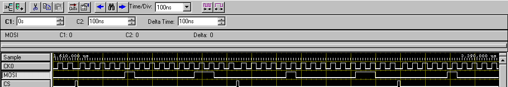
Here's the best I can do right now, as shown in my logic analyzer. Change of the SPI clock speed does not affect installation time and delays that are primary and secondary bottlenecks:
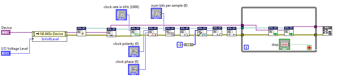
SPI read/write database-
Program: Basic Configuration followed by read/write of SPI block itself in a while loop
Main bottleneck: ~ 450 delay us into iterations of the loop (see Figure 2)
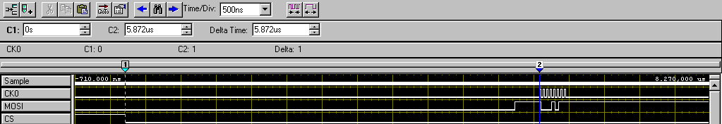
Secondary bottleneck: ~ 6 us delay between falling edge of CS and the first synchronization signal (see Figure 1)
Capture 1 - delay highlighting between CS falling and first SCLK pulse
2 delay highlighting between all iterations of the loop of capture
Scripts of SPI-
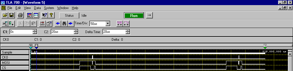
Program: Followed two Script blocks Basic Configuration run in a while loop (to check the two block to block and delay loop iteration)Main bottleneck: ~ 450 delay us into iterations of the loop (see Figure 3, space between the second and third images captured)
Secondary bottleneck: ~ 250 us delay between blocks of Script run consecutive (see Figure 3, space between the first and second captured images)
Capture 3 - highlighting delays consecutive run the Script and delays between while the loop iteration
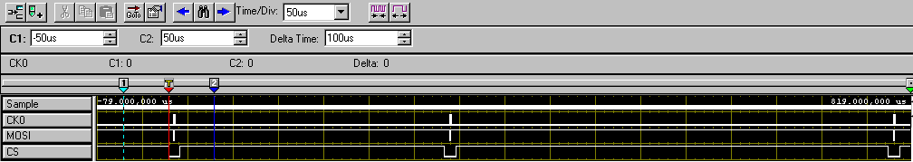
SPI in Streaming- It's the closest to achieve a fast writing speed, but unfortunately, it seems to be only useful for read operations (e.g., ADC), do not write.
Program: Configuration of the base stream followed by start of the flow block
Main bottleneck: impossible to write something else than the data value unique property "wave 1-> MOSI data." I can write a byte array to this property, but it will simply put all these bytes in an image and repeat this framework (see Figure 4) rather than go through each value.
4 - two bytes sent repeatedly using SPI capture stream. Delay of CS is finally good, but no possibility to change the MOSI image to image data.
Hi JBender1,
This show looks like what we would expect for a 8452.
If you need higher performance, I encourage you to watch using a card R or FlexRIO FPGA series for your implementation.
-
With the help of the PIC16F84A in Multisim
Is it possible to visualize outputs of the ports of the 16F84A or output to the Multisim? I tried to display the result of one of the sample files with the Logic Analyzer, but it wouldn't work.
Thank you
Hello
You can use the Oscilloscope or Logic elucidating.
What is the sample file that you tried?
-
Generate a digital waveform like memory on PXI cards
Hello
I'm looking for a way to send a large digital waveforms using a PXI digital signal generator. I saw DIO HS cards, but their memory is smaller than the files that I want to transfer. My understanding is that the PXI backplane bandwidth 132 MB/s. So, I shouldn't be able to stream a digital signal from the memory of the card that is slower than the CPU? For example, 50 Mbits / second (equivalent to only 6.25 MB/s)? However, I think I understand after reading their textbooks is that you cannot continuously transmitting a large waveform of the processor memory file, you must transfer the file to the memory of Council first and then transfer that out.
Does anyone know if there is a way to have a flow of digital signal generation card an arbitrarily large directly from memory to the processor of digital signals? Or, what is the fastest card of pxi digital signal generation that does not require the storage of Council first files?
Thank you
Isaac
Hello Isaac,.
Take a look at the following area developer.
NOR-HSDIO Stream from disk (generation) using Win32 file IO
Note that you will not be able to take full advantage of the maximum rate of update HSDIO devices, because the data must be transferred in a bus. Some other considerations are the width of the data as well as the HSDIO device you select, which may depend on other requirements not related to the size of file or waveform (for example the standard voltage or whether you need hardware compare). For more information, take a look at the developer following items area.
Data streaming of Architectures in the PXI systems
The use of National Instruments Logic Analyzer and generator of test patterns SolutionAdvanced features of e/s high-speed digital devices White Paper Series
-
How to measure the frequency of a clock using meter in LabVIEW?
Hi guys,.
Someone knows how to measure the frequency of a signal introduced in LabVIEW (in the FPGA PXI-7813R), using a counter in LabVIEW?
Essentially, I want to use this counter as a kind of Logic Analyzer.
Thank you, Anoop
I don't know what you mean by "manual". It is all managed in a housing structure.

-
Can't see the terminal emulator port after all control with VISA
Hello
I created a LabVIEW VI to control cycle to PWM channels on a microcontroller FRDM KE02Z reports. The microcontroller, programmed in CodeWarrior, is set up to receive an an input of the terminal string and break it in two parts (the channel name and ratio), which are then applied to the PWM. The code works and I tested with the 2.9 Termite and a Logic Analyzer before ordering through LabVIEW. The problem I had, though, is that I have to completely close LabVIEW to see the port on the new Termite and vice versa.
Previously, I had problems with VI after I something else in it, even a VI almost identical, more open as he was using the same port. I get errors and be unable to get my VI to work again unless I restarted LabVIEW. I was able to fix by adding a VISA flush the IO buffer according to a discussion earlier (http://forums.ni.com/t5/LabVIEW/Timing-issues-with-Serial-Read-Write-can-t-achieve-terminal/m-p/2636... once the configuration of the Port series and at least now I can jump between the screws I am still unable to see the port jumps between LabVIEW and termite, unless I close one;) Close VISA and the closure of the VI are not enough, I must close LabVIEW himself. Is it possible to achieve only within the VI? For example using a VISA or VISA clear Flush at the end (after closing VISA)? If Yes, what is the difference/preference between them?
As I mentioned previously, the VI is functional, but I would like to know what is happening for future considerations. Would appreciate any advice.
Hope to hear from you,
Yusif NurizadeYou have not wired resource VISA through the stop event name so it doesn't close anything.
-
How to split an element in two elements
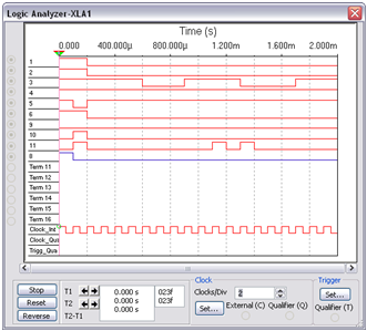
I am currently working with a logic analyzer that displays data in a 2D array. The problem is the only way I can receive data is very troublesome for the analysis. I would like to separate the data so that each column corresponds to a certain value, that I am able. So what I really have to split a column into two columns. Basically if I,
12345678-12345678
12345678-12345678
12345678-12345678
12345678-12345678
And what I want is:
1234 5678 1234 5678
1234 5678 1234 5678
1234 5678 1234 5678
1234 5678 1234 5678
I've been looking for a solution for a long time, any suggestions?
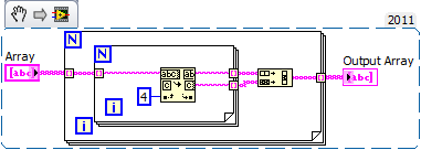
Charles_CLD wrote:
If you are dealing with types of integers, you can use the split function on the pallet of data Conversion.
Woah... what? That the split function is not going to work. If you have the value of base 10 12345678, split, it will not produce 1234 and 5678. Of course, you could argue that the 10 core values are actually base 16 to make the separation, but that will require a conversion of string, and at this time it's easier to cut the string, like this:
Maybe you are looking for
-
Re: My Qosmio F60 - 11f is VERY SLOW and stuck all the time
Hi everyone :) I have a qosmio f60 - 11f with 2.26 to 3.3 with turbo i76 GB of Ram640 GB HHD1 GB Nvidia GT330M graphics the problem is that since I bought it and its slow I don't know why!Now the laptop over 14 months and I did a lot of recovery time
-
I wonder if anyone knows were I can download a copy of the manual for a predator ag5910-e4522u motherboard. IM in the middle of moving the entire system to a new case and the instructions of the need for the connectors of front. Thank you
-
Rundll32 using all the resources of my PC
My computer is very slow. Looking at the processes running, rundll32 uses 97% of my resources to the PC. They just started a month ago. I scanned, defragged and cleaned, and nothing works. How can I fix this error? I also noticed that I have 3 rund
-
CM100 modem does not work with BELKIN router
Hello I just bought a CM100 used on eBay, so I can get rid of my Charter rental, but it doesn't seem to work with my BELKIN router. The model number is BELKIN F5D7230-4. I tried everything, but the 'CONNECT' led will continue to Flash. I thought it w
-
My id of product obtained deleted under my laptop where it was written, now I can't turn it on, what to do?