Generate a digital waveform like memory on PXI cards
Hello
I'm looking for a way to send a large digital waveforms using a PXI digital signal generator. I saw DIO HS cards, but their memory is smaller than the files that I want to transfer. My understanding is that the PXI backplane bandwidth 132 MB/s. So, I shouldn't be able to stream a digital signal from the memory of the card that is slower than the CPU? For example, 50 Mbits / second (equivalent to only 6.25 MB/s)? However, I think I understand after reading their textbooks is that you cannot continuously transmitting a large waveform of the processor memory file, you must transfer the file to the memory of Council first and then transfer that out.
Does anyone know if there is a way to have a flow of digital signal generation card an arbitrarily large directly from memory to the processor of digital signals? Or, what is the fastest card of pxi digital signal generation that does not require the storage of Council first files?
Thank you
Isaac
Hello Isaac,.
Take a look at the following area developer.
NOR-HSDIO Stream from disk (generation) using Win32 file IO
Note that you will not be able to take full advantage of the maximum rate of update HSDIO devices, because the data must be transferred in a bus. Some other considerations are the width of the data as well as the HSDIO device you select, which may depend on other requirements not related to the size of file or waveform (for example the standard voltage or whether you need hardware compare). For more information, take a look at the developer following items area.
Data streaming of Architectures in the PXI systems
The use of National Instruments Logic Analyzer and generator of test patterns Solution
Advanced features of e/s high-speed digital devices White Paper Series
Tags: NI Hardware
Similar Questions
-
How to control each channel of the signals emitted by the generator of digital waveforms?
Generator has digital waveforms of 8 channels. I need to generate two different signals for HSDIO. How to change and control two different ways? In addition, how to translate pinout of the PXI-6541 to channels? I need pin 1,3,29 and 31 control signal individually.
Thank you!!
You need to combine your personal data in a table. The digital waveforms is simply a numeric representation of the binary table. It always boils down to bit 0 of each element of the array will channel 0 (or the first string that you specify in creating dynamic channels). The next bit goes to the next channel. My last post is very clear. To display the table in binary, right-click on a table element, then select the display Format, then select binary. You can also right click on the element, select Visible, then select Radix Show to display the small b before the number. One last thing, in the display Format window, uncheck the box next to the minimum field width to use. Then set the digital just below zone 8. Then select Pad with zeros to the left in the box below.
You should not use waveforms up to what learn you more about how the HSDIO operates on the input data. It is not difficult to combine waveforms, but it is not as clear as it is using an array of U8, U16 or U32.
Trying to explain further. The first number to be written to the HSDIO will have this effect: Bit 0 (LSB) of the number is written to the first HSDIO string you specify. Bit 7 is on channel 8, you specify. If you specify no 8 channels, the bits download ignored. If wiring in a certain number will produce only a single bit on each channel. In other words, the number has already combines the bits of all channels that you specify. Combine you do nothing yourself. Return to my photo on my last post. By wiring in a table, you cause a binary model must be generated.
I hope that is more clear.
-
Digital waveforms of SPI with PXI-6552
I am trying to follow the following tutorial about the PXI-6552 module: http://www.ni.com/white-paper/3671/en.
This is the example that I am referring:
You can also use the data Active event to control the relative delay between the response data and the side assets of the sample clock. For example, you can export the active data on PFI 1 event and send it to the PFI 2, which can be configured as the source of Start command acquisition, as shown in Figure 8. You can export the generation of sample DDC CLK clock out and adjust the STROBE acquisition sample clock.
Figure 9 shows a LabVIEW program that configures and outwardly carries the data Active event and the sample clock. The functions marked with an arrow carried out additional system requirements.
Hello MrHappyAsthma,
I'm looking at your code, and I see that you have two sessions of acquisition while the example has an acquisition and sessions of a generation. This could be the reason for the error.
The digital data control are done right click on the front panel, then go on modern > I/O > digital data.
I hope this helps.
-
static/digital waveform output and low frequency measurement of voltage - SMU-6358
Hello
1. I have an attached VI [digital_voltage_output] who must generate a logical true or false static state in the output of the device/port0/line1 Word to say. When the VI works I click the button several times, but nothing happens to the port0/lines1.
2 such a thing [digital_voltage_waveform_output_square] if I'm trying to generate a digital waveform to pin the same with the waveform generating VI. If I connect a waveform chart to the output of the generator function VI, then the chart will show me the good waveform I want, but still nothing is written to the text file.
3. I have read the manual for the X series cards, but it remains unclear for me a little how to things of the road in LV I have a measure of the frequency measurement VI low frequency that I downloaded. It offers me the ports for the supply frequency - ctr0, 1, 2, etc. As far as I'm concerned the PFI ports are responsible for these types of actions. How can I find out the LV that I want to connect say ctr0 and pfi0? »
I use LV 8.6.
Thank you
Kriváň
Hi Kriváň,
The problem you had with the choice of a specific digital line as a physical channel, is that the control that was previously used in this example was created for a data acquisition task that uses a whole port rather than a specific line. I was able to overcome this problem by removing the control and recreate. The control now gives you the option to choose the specific digital lines e.g. port0/PXI1Slot2/$line0.
I was also able to overcome the error of-200802 you mentioned. I was able to do this in a real constant of wiring at the entrance to auto-start the VI DAQmx writing then remove the DAQmx beginning the subsequent code VI. The modified code is attached.
I hope this helps.
Best regards
Christian Hartshorne
NIUK
-
How can I write a digital waveform to the digital output (traditional DAQ)
Hello
I use a NI 6023e, PCI, with 8 digital outputs. I generated a digital waveform. How can I write for a specific digital production line now?
I only have Labview 7, so I can't use DAQmx.
Thank you very much
-
Generate digital waveforms of high frequency
Hi all
I have some problems. Today, I am generating several digital high frequency waves with my DAQ (PCI-6251) card. The duty cycle of the waveform must be adjustable.
The required frequency is 100 kHz.
To do this, I have tried several solutions:
(1) I used counters in the acquisition of data to generate waveforms, and it worked fine. However, I have only two counters. In my application, I need to at least three waveforms with different cyclical report;
(2) I used a 'loop' and structures 'case' in labview to build the model of waveform and then feed them to the digital I/o. However, the problem with this solution is that the frequency of the wave generated cannot be high.
(3) I used a 'digital' generator in Labview to generate waveforms and then feed them to the digital I/o. In this case, the time base is from an external source (200 kHz). However, with this solution, the cycle is not adjustable.
Please give me some advice on how to make these waveforms. Your assistance is appreciated.
OK, so I may be wrong, but after mucking around for a bit, I realized that the regeneration should be automatic - in other words, if you a pattern to the right and then just leave your VI work in a while loop, you will find that the generation is continuous. Discover the correlation dig write metered in the finder for example Labview. You can leverage this as you get the cyclical report you are looking for. You can split the signal down what you write a single period consisting of a series of 0 and 1. In other words, if you want a wave of 100 kHz with a cycle of 20%, you write a pattern of digital waveforms a 1100000000 at the rate of 1 MHz. Using this technique, the resolution of the cycle will be limited by the on-board clock speed (80 MHz = 0.125%).
Let me know if this makes sense - I am unable to reproduce this on my desktop and have never had to do this before.
Cheers, Matt
-
Jitter in response to signal generator of digital dashboard by using trigger nor tclk with digitizer
I've written a VI that uses NEITHER tclk to synchronize a generator (PXI-5422 named FGEN1) and a digitizer (PXI-5122 named DIGITIZER1). There is also a clock card TIMING3 generating a digital camera.
It seems that can probably be explained by the way TCLK to synchronize, but I don't understand all the details. Could someone help explain this to me?
You are right. NOR-TClk ensures that all synchronized devices start at almost at the same time, to the same sample clock, with timing very tight. Sometimes, the level of synchronization with the devices OR TClk-synchronized beats at the level of the synchronization of the instruments of some competitor channels in the same device. But this is not free, there are compromises and added additional jitter for trigger response time is one of them. Here is an attempt to explain why:
When you use NEITHER-TClk and send a trigger, the devices will respond to relax on the next cycle of the clock once made the trigger signal to the device. Let's say you have several devices all of them even configured with the same clock frequency. You block the signal of PXI_Clk10 using their PLL, so they drift out. But each unit's clock edge will be off, clock +-0.5 cycles. If you send a trigger to each of them, they will respond on the next clock cycle whenever it is, after the arrival of the relaxation to each device with different propagation times, whatever they may be. You get a single clock cycle of jitter on reaction of device to set it off.
When you use NEITHER-TClk, several things happen: all devices are locked on the PXI_Clk10 signal to eliminate drift. The device clocks are then adjusted to a period level secondary clock. Very very tight. Then a clock signal common, slower called TClk is produced inside the devices. All the generation of trigger are delayed to be sent to the next rising edge TClk, and all consumption trigger is delayed to be received at the next front descending TClk. This way you make sure that propagation delays don't mean one of the devices does not react to the trigger until the next clock cycle.
That's why you see jitter above the reaction time of relaxation. When you add devices with different clock settings, so the frequency of the TClk can be slower for a divisible frequency in the device clock frequencies everything is possible. This causes the trigger jitter of reaction time be even slower!
I hope this helps you understand what you see.
-
generate a digital triggering out CH1 (low and high) for the USB-5133
Hello
I would like to generate a digital triggering on the USB 5133 CH1, is this possible? I tried with the PFI 1 successfully but the output is only 3.5 v and I need to 5V, because this trigger signal goes to a box of pulse generates a signal, which is received by the CH0 on the USB-5133. This configuration works on the 5102 OR but because of the treatment, I am obliged to try a new device.
Channel 0 and 1 are only entries then you will not be able to use them to generate a signal. All of our products current digitizer that are recommended for new designs use 3.3V CMOS logic levels for PFI lines in output mode. Your best bet to generate a digital triggering 5V would be to use an external buffer that can accept 3.3V CMOS levels as an input, but is under voltage of 5V. Here are some that might work for you, but there are many others: http://www.onsemi.com/PowerSolutions/product.do?id=M74VHC1GT126DT1G adding a buffer in line with the trigger signal will add delay, so you will need to ensure that it is acceptable for your application.
Hope this helps,
-Matt
-
Continuous output of digital waveforms on PCI-6602
I use 6602 PCI to get a continuous 1 MHz square wave output of DIO1 ~ 32 sequentially controlled by LabVIEW. I Ctr0 to generate a clock 2 MHz and used Ctr0InternalOutput as a source of sample for DIO1 clock ~ 32. I have attached the code and the texture as follows.
The code works fine on PCIe-6251 and digital waveforms of 1 MHz is very stable.
But when I run on PCI-6602 I got an error-200077 (you asked for: sample clock; you can request: on-demand).
6602 PCI does support material timing? I found no information about this its specifications. If she can't, how can I avoid this problem and get what I want? Thank you!
Yi
Version: LabVIEW 8.2
hardware: PCI-6602
Hello
Have you looked at the specification for the 6602?
http://sine.NI.com/NIPs/CDs/view/p/lang/en/NID/1123
Click on "specifications". Scroll down to "digital i/o". Watch "Timing". It clearly says "software".
The DIO lines on this Board are not timed by the hardware. They are clocked by the software. The data sheet that explains very clearly. That's why you see the error clock sample - that the Council can't stand DIO clocked by the hardware.
The 6251 supports clocked by DIO material, so why your code works very well with this Council. You can do the generation of signals with a 6602.
Hope says.
d
-
Hello
I'm working on a project that requires two outputs digital signals at different frequencies. Frequency of the phase 1 is about 1 kHz and is modulated on and off to a pace that will change during the execution of the program. Wave 2 passes from 1 kHz to about 6 kHz while needing to be pretty accurate to the tenth of a Hertz.
Initially, I tried to manage the simultaneous output of signals at different frequencies using a single task on a single 9477 daqmx in a cdaq-9174 chassis. As far as I know, the best way to get a specific frequency in a waveform output is to set the sampling frequency up to 2 times the frequency of the wave that is generated and generate a waveform that is given to each clock cycle. This works very well when it comes to a gesture, but I was unable to get the frequency of the modulated wave (wave 1) remains constant when the frequency of wave 2 modified or vice versa.
I have a few other modules lying around (another 9477, 9403 and 9476) and I thought I would try another task running on a separate module. I find myself receive error-50103 message if I add these modules to my cdaq chassis and run one of the waveforms of a task set to run on the add-on. Is there a way to bypass this error? I guess it would cause by running two digital output on the cdaq-9174 tasks at the same time, but it seems to me that this wouldn't be a problem with an additional module.
How can I have two outputs digital signals, running at the same time, maintaining their independent frequency frequency of the clock of the other sampling rate changes. In addition, because the wave 1 is enabled and disabled at a defined frequency, I use it to set the number of samples to write when you write a range of waveforms in the module (when generating these two waveforms on the same module).
I'm sorry if the explanation was difficult to understand. I've attached an example of error 50103 lifting. This isn't really a part of my project as a whole, but it is the easiest way to reproduce the error.
Thank you
Hi awol.
I have a follow up for you. You encounter the error because the cDAQ chassis has only a timing engine of. You will not be able to perform simultaneous tasks of the call by the hardware. Please see the following knowledge base: http://digital.ni.com/public.nsf/allkb/5E0B829E50ADE1BC86257AC50062B2D2
Mike
-
generate a digital signal for 6722 or 6221
Hello
Thanks first for the help I'm already on this forum.
Now, I have the following problem:
I like to generate a digital signal: high for 300µs, low 300 µs, 300µs high, low 300µs, top for about 2 ms.
I'm looking for a solution how to generate this numerical sequence. At the same time, I will read the information via an analog input (if all goes well, I now have a solution for this problem).
I tried to find examples, but I failed. For the moment, I was not able to produce any numeric sequence that worked.
My hardware is 6722 or 6221 - which should be OK with respect to the calendar.
Thank you
-
How to record a digital waveform with timestamps for each sample?
I am generating a digital stimulus and capture the digital answer using 6552 HSDIO. The captured response is data digital or forms of digital airwaves.
I want to save the captured digital answer and save it in a file in spreadsheet showing the timestamp for each sample. How can I go to a digital waveform to a worksheet that contains all samples and timestamps for each sample?
Comvert digital to analog is just the wrong function. And when you converted to U8, you just threw the calendar information. Try the code below. He puts the time in a single column. If you want to only two columns, its an easy mod.

-
Count the number of 1 is present in digital waveforms obtained by converting the pulse signals.
Hello
I use Analogtodigital.Vi to convert the pulse of the sequences in digital.signals.I am able to get the representation of digital waveforms of impulses.
But how to count the number of 1 is present in the converted digital waveform. I want to count the number of 1 is present in the digital waveform converted.
Thanks in advance.
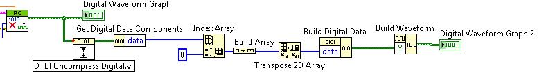
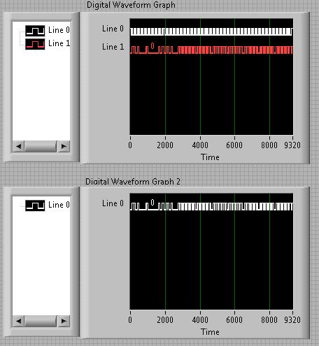
Have you tried the block scheme of similar to the Digital.vi of opening?
It creates an array 2D uncompressed 1 and 0, which is the binary 16 bits A/D conversion of each element in the array Y of the input waveform. You can use the DWDT digital Array.vi Boolean to convert a 2D Boolean table. Then convert Boolean values to 1.0 and summarize the array of integers. The sum must be the number of 1 bits in the digital waveforms.
Lynn
Note: The VI attached is saved in version 8.6. When I have it saved for the previous Version a warning was generated about the possible differences in the versions. Let me know if it doesn't work, and you are using which version of LV.
-
Extract a channel of a digital waveform
I use the I2C Digital Waveform reference Libarary to create a WDT which consists of two lines/channels. I was wondering how I could extract/remove a channel, the wave form and how can I add/merge signals tracks in a single WDT? I looked around for the screws, but nothing seems to work with the WDT.
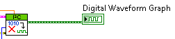
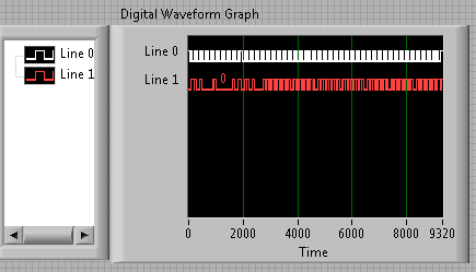
Right now my WDT is like this:
How can I get these two lines in separate WDTs? And then how would I be able to merge them again? Naturally, I don't want to just remove them and merge them, but that would be an example of good practice to demonstrate.
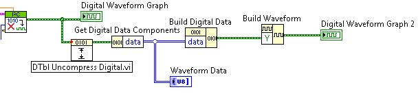
After much trial and frustration, I found a way to do what I was looking for. It is not the most elegant, but it works!
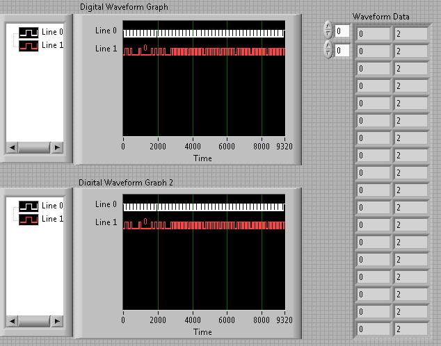
That's how I extracted the two strings in an array and then merge to recreate the original graph:
* Note: The reason why there are 2 in the waveform data table is because my waveform contains 0 and Z instead of 0 and 1. The three States Z corresponds to the 2 digital.
I even took it a little further and extract a single line. This could be changed to extract any line and eventually merge your own custom signals:
-
How I ouptut a digital waveform, it has collated and compare it to the original with a usb-6211 box?
I want a digital waveform to a circuit of output, read the return signal and compare the original to the read signal. I use a usb-6211 housing is it possible and if so, how?
Use a comparator "equals sign", mark the post as a solution if you have the makings of what you wanted.
Maybe you are looking for
-
Change the size of the HARD disk volume
I bought this computer so that I could use the highest GB because I have a lot of iTunes content, unfortunately because my disks are divided into drive(298GB) (Windows) C and D (Data) by car (297 GB) who completed the drive C (Windows) within 15 GB o
-
Hello! I get the error message 'Error 25' when I try to read data to the RT in the FPGA. It has worked before, but then decided to stop working. Weird to notice is that I seem to be able to establish a contact with the FPGA, since the "target open FP
-
My sim card adapter does not work on my laptop.
I have a sim micro sd card for my phone and an adapter for the laptop. When I plug in the adapter with the card, nothing happens, I can't find anywhere on my computer to open the files. Help, please!
-
MacBook Pro at Lac Photo Photosmart Plus?
Hi all I have a 2011 Macbook Pro running OS x 10.6.8 which is the latest update of Snow Leopard. I have a Photosmart Plus B210 print via wifi. I did the software update on my Macbook, everything is up-to-date. I checked the preferences/updates on the
-
Do not let me "send to Illustrator CC.
Just as the title suggests. I want to take the drawings that I do for the draw and put them on Adobe Illustrator CC, but when I hit the button on the iPad app, the charges as if it's still working on it, but nothing happens. Illustrator does not star