Measure the time betw keyframes?
Hi-
It is essentially a question to see if a function exists in AE 7.0/Mac.
I would like to know if there is an easy way to (non-arithmetique) to measure the number of frames between the 2 keyframes.
Can I select 2 keyframes on the same layer of the timeline and have AE just showed me the number of frames (or the amount of time) they are out?
TIA an experienced response.
JL
No, there is not such a function. If you need something like that, create an expression on a text layer, or use a script that measure these things. for expressions, he would use the time indicator to detect the nearest keyframe and a previous / next, whether he should really be coming from a precise selection, only scripts can offer that.
Mylenium
Tags: After Effects
Similar Questions
-
Hallo,
I use the following system:
- OR PXI-1044 with controller NI PXI-8109
- OR PXI-2564 switch module to turn on the monitor of my test device
- Data acquisition multifunction NI PXI-6259 to measure the signal that responded to the questionnaire jump
The two cards are the same - PXI trigger bus. For both, PXI-2564 and PXI-6259 I use DAQmx to set the reading and writing of the channels.
Now, I want to measure the time between the digital output, my unit turns and the analog input, which measures the response of my system.
I can't do work by myself, please help me!
I thank Ludwig.
Hi Ludwig,.
If you can't give us any VI we have difficulties with to help you.
Because I Donat knowledge how your program is mounted it is not easy to know where you should enter signals.
Here's a question similar to yours:
http://forums.NI.com/T5/LabVIEW/best-way-to-measure-time/TD-p/178704
and 2 external links:
http://www.ehow.com/how_8698983_measure-time-LabVIEW.html
http://objectmix.com/LabVIEW/385152-how-can-i-use-LabVIEW-measure-time-between-analog-pulses.html
-
Measure the time between the ridges of the periodic input signal
We have built a circuit which is supposed to mimic an Exercycle. We have an IR switch and a spinning wheel, the rccb meets a comparator circuit and the output of the element of comparison, we have running in LabView. We successfully were able to measure the number of rotations of the wheel and the total distance travelled by the wheel, but are struggling to measure speed. We cannot find a way to measure the time between picks in real time, which we could then divide the wheel circumference and calculate the speed in real time. The VI I posted has a square wave simulated rather than the signal we receive on our circuit. Thanks in advance for the help.
Jon and David
I think you're overloading the things trying to get the time between two pulses. Instead, you can use the VI Express your measures and select frequency for her custom. Then, you can multiply the circumference of the wheel of the frequency to get the speed.
I hope this helps.
-Christina
-
How to measure the time elapsed between two steps?
Hello
In my script, I ask the subsequences. How can I measure the time it takes each subsequence?
Something like:
Statement: StationGlobals.TimeElapsed = 0
-> SOMETHING HERE TO START A COUNTER<>
call sous-suite
Popup: Str (TimeElapsed)
Thanks for help
StationGlobals.Time = Seconds()
... / / stuff in time
StationGlobals.Time = Seconds() - StationGlobals.Time
You can also view the sample report of basic step in 2012 TestStand time (you can now download an eval).
-
How can I measure the time between the two edges of successive increase, using digital input...
Hello
I'm trying to measure the time in seconds between each two successive rising edges on a digital input.
So far I managed to detect the rising edge, increment a counter at each rising edge and take the time during which the increase is edge
all I need now is subtract edge currently rising from the previous era of edge rising to calculate (T), which can be 1/frequency and display in real time for the user.
but I do not know how to do this

Can someone help me please!
Note: while I am in a position varies between 200 ms - 2 seconds
-
How can I measure the time between each two successive increase edges, using digital input?
Hello
I have tried two measure the time in seconds between each two successive rising edges on a digital input.
So far I managed to detect the rising edge, increment a counter at each rising edge and take the time during which the increase is edge
all I need now is subtract edge currently rising from the previous era of edge rising to calculate (T), which can be 1/frequency and display in real time for the user.
but I do not know how to do this
Can someone help me please!
Woah!

Sorry Apok, but your code becomes much too complicated and salty. I don't think that all records to offset or Boolean conversion/operators are necessary at all.
If you want to measure the time between two keys so it's another (much less complicated) way. It simply records the time when press button in a registry change, then compares the two.
-
Measure the time between two digital pulse
Hello
For a non-critical calendar application, I need to measure the time interval between consecutive TTL pulses, ranging from the order of 0.5 s for a few seconds, with a low accuracy of +/-10-50ms. The interval being measured varies between the rising edge of the first pulse and the front of the next and so on.
I have several input lines I need to deal with. Because it's a critical machination low cost, I don't want to use digital counters for each line, so I work with an acquisition of data USB6008 and have connected the input rows TTL on the digital inputs of the device. Avoiding will be sufficient.
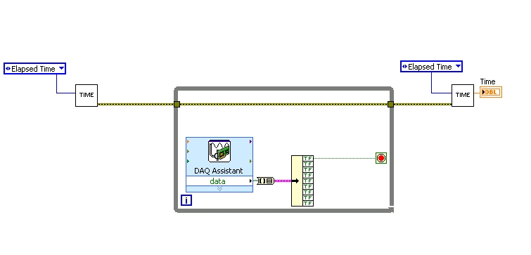
I found a good example of VI on discussion forums that does almost the same thing, only it uses instead of the DAQ Assistant user input. The VI works including the time the program going on in a while loop. I replaced with the DAQ Assistant output (a channel) user input in the hope that it is still work.
When I run the program in "run once" mode, it seems to work perfectly. However, in "continuous run" it measures only a very small interval, probably just the time between two samples. I think it has something to do with the help of a while loop in combination with the DAQ Assistant. Anyone who has any suggestions how to solve this problem?
Thank you!
OK... first of all, you should never use the button "run continuously. I wish that NEITHER would be to eliminate it, but told me that it is sometimes useful for debugging. If you want your program to run over and over again, use a while loop with a stop"" button.
If I'm reading your code correctly, you make your initial moment, and then collect data from data acquisition. When one of the channels is "T", you stop your loop and the end time of capture. (By the way, why you convert your table to a cluster? Why not just index the appropriate channel in the table directly?)
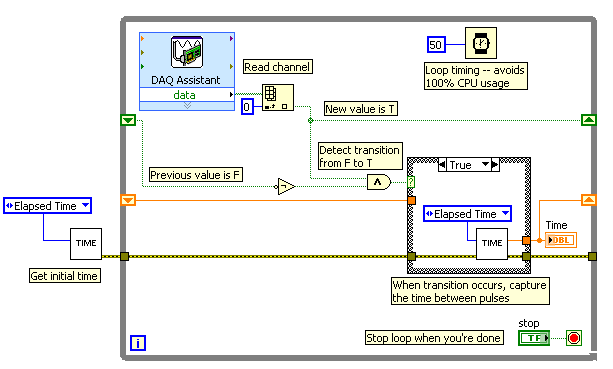
Since you want to capture the time between two consecutive pulses, you need to know when a transition has occurred... i. e when your digital line went from F (no pulse) to T (pulse start). This will give you your forehead. Right now, all you're doing is looking for a value T - so you have no way of knowing if you are looking for to the previous impulse again, or a new impetus. You also burn 100% of your processor with the way you have your programme in place.
You need a small loop delay so that your VI is not 100% of your hogs CPU time. Given that you can live with an accuracy of 50msec, what I suggest that you use.
See attached picture for you give an idea of how to implement. He will probably need some refining operations, but it should point you in the right direction.
I hope this helps.
-
Measure the time in seconds each time run you a VI
Dear people,
I'm trying to measure the speed of a wheel using a magnetic sensor and other settings in the vehicle. What I also need to document in my project is the time elapsed (in seconds) each time that you run the program. Is there a way where you can measure the elapsed time in seconds in labview?
Any sort of suggestions or examples would be useful.
Below is an example of how I wanted my final to watch output file.
Time (sec) | Speed (mph). Acceleration |
0 23 5
1 24 6
2 25 7
Thank you in advance!
Rahul-
Hi iZACHdx,
That's what I was looking for exactly! Thanks for the simple example.
Thank you
Piraux
-
Measure the time of the rising edges of a digital stream using a USB-6341
I have a DAQ USB-6341 map.
I use Measurement Studio (writing code in c#) on a Windows 7 computer.
I'm relatively new to the DAQ cards, programming, so I could ask something that is obvious (sorry if this is the case).
I went out a stream of digital pulses to an analog output channel. I wired this channel to one input of the meter channel. I am able to measure the number of edges upward to the inlet of the meter channel (since the digial flow is continuous, the number of rising edges increases with time).
I would like a time stamp of each rising transition and I like to keep these timestamps in a table without ever growing (or maybe bin these timestamps in a histogram).
Set up the meter channel to provide the timestamp data? (rather than just count)
Thank you for your help.
WRB,
The meter must be able to measure the relative time between the different edges of your signal. To do this, you will take care to set the meter to measure time. It will measure how long a full period of your signal takes. You can configure edge that you want to start with. You'll want to set up your timed 'implied' measure. This sets up the meter to automatically take action whenever a period is over. While it's not exactly a timestamp, you can find the distance between two edges by adding the time periods between the banks in question.
I see another technique that you can use. This would put the counter to edges of County one of the basics of time of your device (it has 100 KHz, 20 MHz and 100 MHz bases long). Then configure the task to use your signal as a sample (configuration to use rising edge) clock. Whenever the song occurs, you will get the number of ticks ticks selected timebase that took place at that time. One thing to note here, however, is that the counters are 32-bit wide, so your code will have to manage the overthrow of this charge if you are using a fast time and base running for long periods of time.
Hope that helps,
Dan
-
How to measure the time, that the slider flew over an area reactive
Hi all
I have a task in which participants will have to make a decision with two options. Therefore, I created two spots, one for each option. I want to measure is the time that the "flat" mousecursor on each option before a choice has been done (one of the two hot spots clicked). Thus, for example: If a user first flat 2.5 seconds over option 1, then go to option 2, flat il.45 seconds, then go to option 1 again, hover pendant.5 seconds before clicking, I want to save these two values (2.5 +.5 = 3.0 s to option 2 for option 1 et.45 s) what is performed on a hotspot. I thought using a conditional in my interaction icon something similar to ObjecOver (which gives what icon display the cursor is currently above), but then to have something like HotspotOver (which does not exist). Anyone know how I can accomplish these measure hovertimes?Kind regards
FrankThe solution I came up with that has five hot spots. First a calculation icon: OptionTimes: = [0,0]
Then the interaction with hotspots: click on option 1, option cursor area 1, the option click 2, cursor in option 2, the single area finally a hotspot that surrounds all the other
In the display area hot point type for option 1, I have the calculation:
Option: = 1
OptionStartTime: = SystemSeconds
I hope you can see where this goes. There is a similar calc for option 2 in the cursor in option 2 of the area. It affects only the number of Option 2. In the latest hotspot that surrounds the other, I have this:
OptionTimes [Option]: = OptionTimes [Option] + SystemSeconds - OptionStartTime
When the user rolls over an option and then leaves, the hotspot that surround other intercepts and records the time they spent. You also need same calc in the way of response for both options catch the time taken by looking at the option just before clicking in their choice.
Mike
-
Possible tweak to the time remap KeyFrame spacing?
I do a lot of time remap keyframe tweaking in AE, so I tend to zoom in the timeline.
Is there a way to reduce the spacing between frames? Then, I'll be able to display more images on the screen. Thank you!
Nope.
Mylenium
-
How to measure the time for each mapping?
I use oracle11g with OWB.
I have several mapping and each dimension tables to update the mapping.
I want to measure how long it takes to complete each mapping. What is the best way to find the total time for each mapping.
One way is, we can have POST MAPPING and PROCESS of MAPPING PRE. I can trigger the stored procedure to enter the start time and the end time of each match. On this basis, I can calculate the total time for each mapping. But I have 50 mapping. Now, I need to write 50 different stored procedure and open the POST-PROCESSING of the MAPPING and PROCESS OF MAPPING of the PRE for each mapping. It is complex.
Is there another way, we enter the total for each mapping of execution? Y at - it that no data in OWF_ MGR dictionary can help on this?
I would be grateful if someone can help me on this.He will remain forever unless you purge it explicitly.
See you soon
Katia -
Pulse ultrasonic 40 kHz and the time before receiving the pulse.
Hello
I developed the following circuits:
TX: a Circuit that generates a 40 kHz of frequency using a LM555, the LM555 is connected to a gate AND who, when you use the test on MyDAQ Panel (6216) I put cntr0 and set it to the detection of edge I can count the number of detections of edge when I activate the port up and when I turn it on it low stop recording of the counties.
Rx: Reception Circuit contains an op amp that is introduced in a LM567CN tone decoder which is set at 40 Khz. when the receiver PLL circuit locks on the 40 kHz signal switches LM567 pin 8 output ground.
Question: I am NEITHER very new and ask yourself where the starting point would be to create a VI that will trigger the Tx circuit, and then measures the time required for the circuit of Rx to receive the signal, this intitial will carried out through the air and then I want to move it through a meduim such as water. Someone at - he tried or seen anything that would be useful to create a vi that correspond to this.
Any help would be greatly appericated.
Phil
Using a myDAQ or a 6216? You mentioned the two... I'll assume 6216:
You'll want a task of separating two edgeand also a task of digital output.
The digital output control signal enable for the LM555. Connect from the digital output line at your door AND as well as a PFI lines on the 6216 (this will be the "first" edge). Connect pin 8 of the LM567 to a different line of the PFI on the 6216 (the 'second' edge). You can configure the polarity up/down via the Create channel VI (looks like your second advantage is going to be 'falling').
Programming would be as follows (in order):
1 configure the tasks as shown in the related examples (i.e. channel to create / configure synchronization).
2. start the task of digital output.
3. write the 'low' digital output to ensure that it is initialized.
4. start the task of separation on both sides (it should be buffered as in the example linked even if you are only reading a sample).
5 write the digital output 'high '.
6. reading (a sample) the task of separation on both sides. Specify a time for read long enough to ensure that the falling edge is considered.
7. write the 'low' digital output (assuming that you want to disable the Tx when you are finished with the test)
8. stop and disable the two tasks.
The measured result will be a 12.5 ns resolution using the time base 80 MHz by default on the 6216.
Best regards
-
measure the distance between 2 impulses (PCI-6221)
Hello
I have a digital signal that sends a pair of impulses (100ns width each) roughly every 100ms and I measure the time between two pulses of a pair (with a resolution of 100 ns).
For the moment, I got a card PCI-6221 to accomplish this task. Unfortunately, I have no solution until now only measures of counter, I found measure time between constant frequency signals, i.e. they cannot measure the distance between 2 single pulses.Any help / ideas / or even telling me that it is impossible to solve this task are appreciated
Are the two pulses on the same line?
If so, you need to just configure a task of the measurement period. If they are on separate lines, you would use a task of "separation of two-edge.
You might be to throw off by the timing of it:
If you do not configure implicit synchronization in your task, will start on the first edge after DAQmx Read is called. Thus, in order to intercept the signal, that you must configure your task, call DAQmx Read and then start your two squares.
If you want the task to control the signal continuously, you must configure name timing. In this case, you will receive a sample on each rising edge of the external signal (assuming that the two impulses on the same line) - If you start the task of counter before starting the production of pulses (which you probably should), then the same samples correspond to the time between pulses, the odd samples would be the time between each series of pulses.
More information on modes of counting on the 6221 lie in the M series user manual.
Best regards
-
How to increase the resolution of the timer loop?
Hi all
I use myRIO 1900 for my project of Active noise cancellation. I need to process the audio signal @44. rate of 1 kHz sampling and 50 samples per image. So, I use myRIO personality of broadband.
Now my problem is simple, I want to measure the time each iteration (loop). I went for the number of cycles normal (msec). Used as a standard [https://decibel.ni.com/content/docs/DOC-11078].
But my value of the indicator oscillates between 1 and 2. It is supposed to be 1.13msec, but how to find the exact value of timer?
I think, I can't increase the resolution of tick count (msec) as it is by default is 1 ms resolution and I can't use the clock source external I use myRIO.
Help me calculate the precise time of loop.
Thank you.
RT has express VIs for timers. You can use this: http://zone.ni.com/reference/en-XX/help/371361J-01/lvexpress/tick_count/
Maybe you are looking for
-
Printer HP Deskjet D1460 does not respond in the laptop but printing show print option
Mr President, 2 years ago, my hp deskjet d1460 works well in Asus X54c. After 2 years when I placed the new cartridge 21-22 don't is not printing. But the printer shows printing. In short, through control of the laptop I couldn't make answer to this
-
I downloaded a virus on my computer that wouldn't let my computer startup message wasn't system32\hal.dll Windows didn't start because the following file is missing or damaged. I went into the recovery console and tried to repair the files what happ
-
Pavillion DV7 - 4032 VS Windows8
Hey guys! It's my pc: http://h10025.www1.hp.com/ewfrf/wc/softwareCategory?os=4063&lc=da&cc=dk&dlc=da&sw_lang=&product=4267... is it possible for me to run Windows 8?and where I should rally drivers for GFX MOBO, CPU and sound card? I'd like a quick g
-
E-fax: all systems existing operating provide built in e-faxing time send and receive capabilities?
-
I don't know if this is the right forum, I'm sorry if not. I need help, but if you can help... lately, whenever I try to open a file of internet download it tries to open it with Adobe Reader, which causes me to get an error message: "Adobe Reader c