Measuring FIFO device
Hello world
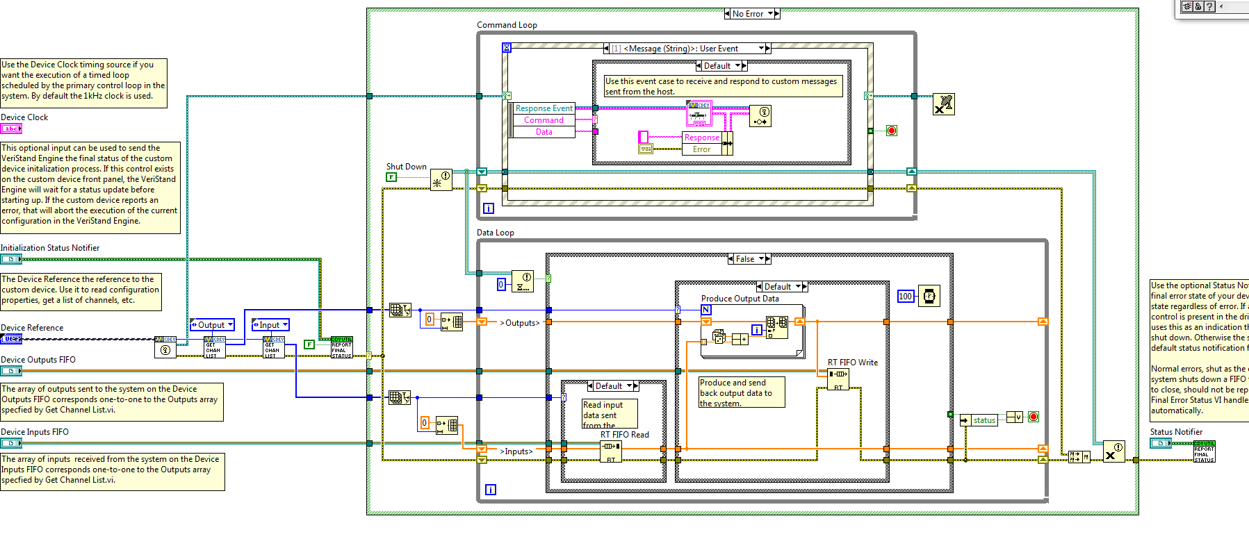
I have a custom device which initializes without problems, but I can't understand how to use at run time. I used the Inline HW model to create the device. The definition of system deploys on the FPGA target, but I can't read or write to the FIFO. For the purposes of learning, I write just three constants true that activate the three LEDs chassis. When I deploy to the target, the lights are not upward.
I created a VI using similar code that doesn't use VeriStand. The difference is that I use a while loop to read and write items FIFO in functional VI, while the generated custom device a model pilot VI that uses a case structure and an enum to determine its mode. I have to do something wrong... does anyone have pointers?
Thank you
After scratching my head for hours, I finally realized that I never wired a real constant to the control that actually starts my FPGA VI... Oops! Thanks for your time.
Tags: NI Products
Similar Questions
-
Question again on the custom device.
If there are 200 channels of output but every 100ms only 40 of them updated by the driver.
Is it possible to write only the 40 channel data at the exit of the FIFO device at a time?
What is the write FIFO RT speed when writing 200 channels of data at once?
Thank you.
If your custom device is a custom device inline, you update only the channels dedicated by iteration.
In the case of an asynchronous (parallel) custom, you are forced to write always all the channel stack regardless of what happened to values. (if none of the values have changed, so it's ok not to call the Write FIFO function).
FIFO writing does not cause a huge head.
You can compare easily than yourself well.
Tom
-
Customized for the RT FIFO device details
Hello
I have a few questions about the FIFO VeriStand in a custom device asyncrounous.
I saw a post earlier where a - 1 to the function of reading of FIFO of RT for him to wait indefinitely for an item to enter the FIFO. This allows pseudo - synchronize the PCL with a device custom asyncrounous. I wonder if this causes the boundary wire custom sleep or it stay active and keep returning? Is it possible to change the polling to blocking?
Another quick question, if I only want to write to the RT FIFO when the data has changed it will cause unforeseen problems? As the channels time or need to wake up or something? Certain conditions can only write channels once every 1000 iterations of the PCL and loop device custom.
I know that I can not write the channels selected in a FIFO RT, but can I create multiple FIFOs in a custom device to actually do the same thing? I imagine then having the outputs 1, outputs etc 2 in VeriStand.
Thank you
B
Hi B,
If you look at the RT VI pilot generated from custom device model you will see exactly what is happening. If you set the time-out for the reading of FIFO-1 then the botton loop will be essentially suspended unless there are items to read in the FIFO. Meanwhile, the thread will always be active because the RT read that VI is querying data during the time specified in the timeout. I don't think that there is a way to change the FIFO mode to blocking since the dismissal of the FIFO is spent Veristand engine to the RT VI driver.
The PCL writes and reads data from and to asynchronous custom FIFO device at each step of the execution. In your custom device, you can configure to read and process data of the 1000th step. I don't see any problems with it.
You can have a FIFO for input channels and a FIFO for the output channels. You can write to an output channel given by writing data in a function index element in the output array that is passed to the function RT FIFO Write.
-
entry 100 pin voltage measure switching device
I have a number of 100 harness cable pin I need to check the output voltage on. I need to be able to select the two pins (tension and back) and move them towards a pass to tension. Unfortunately, each cable is unique, so I have to be able to select any combination of possible pin pair. Any ideas on the architecture of mux/switch to use is appreciated.
stratcat wrote:
If I am correctly each pin will go to two of the columns. So I turn on a PIN (side) on the pin (back side) column an and the other two column. Looks like my thoughts once I made the first post of the use of two PXI-2569 cards would also work. Choose the high pin on one card and the PIN back on the other.
In fact, I told you 1 1 column axis. Then you have a column to the side as high DMM and a column for the low side of DMM. Since you have 4 rows, you can easily connect any axis of part and on the other of the DMM when you plug a different pin on the other side of the DMM through the matrix.
-
NOR-IMAQdx ICube NS4133BU uses wrong exposure values
Hello
I use a DirectShow supported CMOS-USB-Cam (ICube NS41133BU, Net-GmbH). This camera is displayed correctly in the Explorer of Measurement & Automation devices NOR-IMAQdx. I can also access and modify several parameters of the cam.
BUT: when I want to change the exposure time of the camera (which is a crucial parameter for my app) I can enter only a few numbers which are still twice the number preceding (e.g., 0.1, 0.2, 0.4, 0.8, 1.6)--> I can not chosen exposure values I want to because when I implement cela in my Vi and enter some value for duration of exposure , the camera will use a different value (the next smallest value that is available). However, this seems not to be a problem of the pilot of the camera or DirectShow support as it works perfectly with other software like 'AMCAP '.
http://www.noeld.com/programs.asp?cat=video#StillCapLib
All solutions?
Thanks in advance!
Philipp
Yes, there are available screws to expose the internal image data such as pointers to image data that 3rd - party code can use to integrate into their own software/driver development kit functions. Depending on how their functions are defined, you have perhaps trivial to wrap as - is in LabVIEW or you will have to compile your own packaging C.
Eric
-
Hello
I have a question about BER and SNR and I would appreciate your help.
I have a power Spectrum (live with the presence of interference) and I would like to know in what parts of the spectrum, I can achieve a target BER (lets say 10th-3)
My suggestion was to first determine the signal investment ratio on the graph (for BPSK) and then search for available positions in the spectrum that can give me this SNR
So say for 10-3 BER, en No. DB 9 (on the graph)
If Eb (dB) = 9 (dB) + No. (dB) or Eb (dBm) = 39 (dBm) + No. (dBm)
now my questions are?
1 - instead of BER can I focus on NRS and are my calculations correct?
2-noise background in my power spectrum is observed from BDP-110-130 dBm is not a value constant .what should I do in this situation to find Eb?
3. What about interference? because WLAN is perhaps the received power - 50dBm in this situation that the SNR appropriate therefore to achieve this BER?
is it correct to say Eb should be = - 50 + 39 (dBm)
I thik find positions them avaiable in the spectrum (especially 2.4 GHz) to achieve a certain BER or SNR should not be as easy as I think.
Hi tintin99, the calculation seems to me.
For the second question, I don't know what application you are considering, so it is difficult to answer. If you measure performance to highlight, I'd go for the peak noise. To help us to give an exact answer, you provide more information about your application. For example, NEITHER-6115. The following link will be useful: NOR-6115 noise floor.
In case you're only interested in theoretically calculate the background noise, please check for the radio receiver noise floor. According to the definition, you can calculate the background noise as follows:
Background noise =-174 + NF + 10 log bandwidth
Where NF is the noise figure.
I hope my answers help. Still once, for questions related to the concepts of communications, please try discussion forum, I mentioned above. RF meter of NOR, please post to measure RF devices
-
unknown table to the LV9 chart size
The attached program is used to measure a device at work, which currently has 3-band, for an indefinite period. It works great (although I'm sure that it is not written in recommended NEITHER!).
My problem is changing the software to test devices that do not have 3 bands. For example, we have a device that has 128 bands. The majority of the program didn't need any changes, only the changes are essentially for the graph to draw.
Ive wrote the code where I need help. The chart is necessary to trace the currents over time and also to trace the temperature over time (on the same graph). For a quick visual, it's all right.
Or can anyone point me in the direction of a relevant example?
Merry Christmas.
Take a look at the attached vi, that help you?
-
The first step with multiplexer
Hello everyone,
This is the first time, we will use und multiplexer, we don't know what we can do. I have a practical training at the University, and we should use multiplexer with labveiw 2012
Description:
-in this project, we have a program, this programm for signal measurement and this programm worked same will. Our role in this project, we will extend this Programm, that we will use multiplexer with 20 entrance and exit.
-We go to conenct 20 devices in a laptop computer to measure the parallel of 20 devices (signals). the time between each Signal on the output side should be of 5 ms.
My question is: what we don first after the connection of devices-20? We should install the driver? What function do stupid to write question? should we write RS232 function "funktion write, read, open serial... etc." or it takes not just with multiplexer? ' " I know, it's a stupid question, but I'm sorry we don't know what we can do, and as I say it is the first practical training.
Thank you very much
Hello
I use a multiplexer to connect several devices to measure the values. I use the multiplexer "USB-ERB-24", so I can measure 24 devices at the same time. I already ordered the multiplexer, but so far it is not getting... So I thought to prepare the software.
My question is, I've programmed the multiplexer blindly and would like you checked my program, if it's just
On the picture you can see that I used "wait" and "timing" funktion release time because should probably be 50 ms... This means that the data is read from a device, and after 50ms must read data from the next connected device... etc? Here, I have not defined a fixed value for the time to release... maybe I have an error and my multiplexer will made to automatically release time because in the Datenscheet stand at the release time which is 50 ms? I don't know if the the mux do this automatically an i donot need to use here "Wait" or function "sync"?
The second part of the program is: I will not use a single multiplexer but two multiplexers. So I can measure 47 instead of 24 aircraft. In the last relay (nr. 24 entries) of the multiplexer1 connect the second multiplexer. for this purpose, it was necessary to extend my program... See image 2 in ULX 'write.vi', I joined to the smallest feature... So it will be tested with data on how many devices are connected, in other words, he checked with the creation of the matrix whose values are True (true value = connected device) and real values will be in a new table added, after generating the new table, it will determine the size of the array (the new table size) If the size of the table = 24 ==> the second mutiplexcer is connected and the waiting time (time releasing = 24 * output wait time). It is true that I have do the extension in "write data"? Do you think that so far is everything is ok, or not?
Thank you for your help -
Synchronization of multiple unit with the PXI-1044-6250 M-6143S
Hi all
I have a problem with several device synchronize with my PXI system: when starting a measurement, the devices do not start at the same time despite using a trigger to start. The delay in the start time varies randomly between 150 nanoseconds and about 80 milliseconds.
My PXI system consists of the following:
- Controller PXI-8108
- Chassis PXI-1044
- 6 * Series S PXI-6143 (Slots 2-7)
- 1 * Series PXI - 6250 M (8 slots)
The software in use is LabVIEW 8.2.1, NOR-DAQmx 8.9 and MAX 4.5. "The trigger line routing" is set to "Dynamic" for all 8 lines.
I created 3 tasks in the attached VI: task 1 ('Drehimpulsgeber' = encoder, 1 channel, rate: 1.25MS / s), task 2 ("Heißfilme 1-8" = hot-film probe No. 1-8, 8-channel, 250 ksps through rate / s) and task 3 ("Heißfilme 9-16" = hot-film probe No. 9-16, 8 channels, rates by way of 250 ksps / s). 3 tasks are expected to start at the same time acquire the analog voltage by pressing the button "Start". "." As the trigger for the beginning, I use a digital pulse created on/PXI1/PXI_Trig0.
After reading samples, the first timestamp recorded for each task is retrieved, displayed and the delay time is calculated (see boxes 'Start time' and 'Time Delay' on the front panel).
How can I optimize to synchronize the start of all three devices without getting this random delay?
Thank you in advance.
Kind regards
Matze
Hi MatzeK,
Here's another one. Could you please try this too and send me information on success?
TomBaum
-
Multiplexing of signals microvolt and conditioning of the right signals
Hello
We have 22 signals in our system. We must be able to measure any subset of these 22 signals. Usually, we carry out a number of measures IV 4points of separate devices on a SUT (sample to be analyzed). Two of the 22 signals may represent the pair of voltage measure 4-point IV, depending on how it was KNOWN is bonded. The level of the signal of tensions is in the 100s in the uV range and I need a precision as much as possible, so the unit or same sup - uV numbers. So far, we had all the 22 signals connected to a box (selfmade) acting as a distribution point, where a connector (SMB) is available for each signal. We then manually choose which two of the 22 that signals will be connected to a differential amplifier silent instrumentation (also selfbuilt), according to it was KNOWN patterns of liaison. The amplifier with a gain of typically 1000, returns the signal to an acquisition card. The current (excitation) is read separately.
There is a problem with that. We need to manually switch the connectors in the distribution box to select a different device on it was KNOWN and flows to the amplifier. This is not good for a number of reasons that I can't go here.
Therefore, I would like to multiplex these 22 signals to several outputs (for future scalability) who will be wired for the conditioning of signals. There is no manual connection/disconnection of these signals in this way. The first question is: can a matrix switch or multiplexer be used to route signals reliable microvolt? If so, then what kind: electromechanical, Reed relay or a transistor? Is the thermal EMF in the specifications of multiplexer/matrix relay just a lag, or is - that noise?
The second question is: what card/signal acquisition solution (so no selfmade equipment and legacy) products OR only using the same line that the matrix/mux can reach 1uV accuracy of treatment? For us, offset offset is not a problem since we measure the device in 2 quadrants and later cancel it in the software but the noise (and get the accuracy) is important. Our amplifier has a background noise of 3nV/sqrtHz and a bandwidth of 15 kHz. The system to replace must be comparable. I have the choice between:
- the SCXI based ones, instrumentation isolation (4ch) 1121 or 1122 amplifier modules (16 channels), with a ground noise that I calculate 20 and 30nV/sqrtHz respectively. They already have some functions of multiplexing btw.
- the PXI 628 x with a background noise that I calculate through 10nV/sqrtHz
- the PXI 446 x with the noise floor low 8nV/sqrtHz as stated in the technical data sheet
Module 4-way universal 24-bit NI 9219, who works with 2 samples per second has a very low noise total, but at a very low sampling frequency and I can't consider comparable to what we have now. In addition, the system must be able to have a few kHz bandwidth for dynamic action in the future.
Y at - it any other ideas?
Greetings
Aleksandar Andreski
-
LabVIEW 7.1.1 crash on right-click Subvi
We started to have a problem on a computer, with a 3.4 ghz, card mother dual core to Intel, win XP pro. When a Subvi, usually homemade and started under a previous version of labview, is right click on the scheme, we have a dialog box indicating that "Labview has encountered a problem and needs to close." No joke. It goes away as someone files a lawsuit in paternity. We use some Measurement Computing devices, and their vi seems particularly prone to this. I read the previous thread of 2005, which did not offer much help. Have already installed drivers updated graphics Intel (seemed set for a while, but NOT), removed/reinstalled Labview, tried repair by councils Travis H. in fourm thread above:
ttp://forums.NI.com/NI/board/message?board.ID=170&message.ID=105471&query.ID=402919#M105471
Also tried to set the computer to use a kernel in the BIOS. Anyone have any new ideas?
Problem solved. I moved the offending userlib to another machine and reproduce the problem. Then copied dir.mnu file fronm the good user.lib to the bad user.lib, and the problem disappeared. I had tried to change one that was on the machine of problem a long time ago. He showed a userlib another icon in the palette userlib, which seemed strange to me, but never occurred to me that this could bring down the entire system. All fixed now. Something about the UI in this palette editor, never made sense to me. I have probably committed a sin and walked away. Proabably made no difference until we went to v7.1.
-
Using measure computing library UL (device USB-1208FS) with CVI
Hello
I'm trying to implement the system of company Measurement Computing USB-1208FS (www.mccdaq.com) in our test software tool which has been programmed in Ansi C using the CVI compiler.
To make the first steps, I am building an executable based on the Ansi C «DaqInScan01.c» example code
While I have no problem with the compilation of the code, the linker complains with errors shown below. Although the cbw32.lib is registered with my project, ICB seems not to be able to reference the functions of the library.
What I am doing wrong?
Is there the CVI samples available to guide me in the first steps regarding this device?
I use WinXP SP3, CVI is version 9.01Thank you for your support
Hello IEE_newsoft,
Looking at the screenshot you posted, a recommendation is to make sure that the header file and library with the same name, also have you been able to call the dll or lib successfully in another environment, IE such as visual studio to check there is nothing wrong with the files. Also look at this Developers Zone,http://zone.ni.com/devzone/cda/tut/p/id/3453 it shows you how use a third party dll of CVI and http://zone.ni.com/devzone/cda/tut/p/id/8503 shows you how you can use either dynamic or static linking to call your dll.
Hope this helps
-
Measurement period semi PWM input: requires a custom device?
Hello
I need to read a pwm on my X-series card entry in the VS2011 environment. In LV, this would be by a half measure. Now how can I do this in VS2011? It seems that I must take this vi LV making periods of semi and "decent" soul in a device custom vs. Is this true?
THX.
L.
myself... Yes it certainly looks like him.
-
measurement of input frequency TTL with sheet metal entered on a device USB 6363
Hi all
Is there a simple LabView vi to measure the frequency of entry TTL cable for the entrance/s, four counters available on a device USB 6363? I have LabView 2014 FDS installed. I guess using 2 4 meters would be better than 1 for 32-bit resolution, correct?
Thank you
John
Hi jac2015,
There is an example of a measure of frequency located in LabVIEW help-> find examples-> material-> DAQmx entry and exit-> entrance of counter-> meter - reading pulse width and frequency (continuous) .vi
Take a look at it and see if that helps. There is also a very useful white paper on considerations to make when measuring frequency, you can find here:
«Measures of frequency: practical Guide»
http://www.NI.com/Tutorial/7111/en/
The main considerations is how often should the signal you want to measure?
I hope this helps!
-
With the help of several NI USB-TC01 Thermocouple measuring devices
I am currently set up with 1 NI USB-TC01 (http://sine.ni.com/nips/cds/view/p/lang/en/nid/208177), and everything works fine. My question is, can Labview control multiple TC01s simultaneously or I have to buy the NI USB-9211 has (http://sine.ni.com/nips/cds/view/p/lang/en/nid/201881#) to manage multiple thermocouple measures at the same time?
Thank you
Ben
Ben,
I didn't know we even had this device but I think that all of the information you want are in the link below.
http://digital.NI.com/public.nsf/allkb/7A9DAE5554C9D503862576FC005A3908
If you use the built in program, it is four devices, if you are using LabVIEW, you are limited to 127 devices. I don't know if several windows built-in software should be used if you use a LabVIEW.
Maybe you are looking for
-
When I get a message from my doctor to log on its website secure, and I try to do, I get the message that Firefox has prevented (something or someone... don't remember) to redirect to another page. It's already happened.
-
12.3.3 Installationavecuneracine W10 64 bit iTunes problems
Hi all Having some problems... on Windows 10 64 bit, Dell XPS update about 5 years (so an older video card) and get a message indicating: Tried the update/install for video cards more old but same message Anyone has an idea on how to solve it please?
-
So, I got the error hard drive 1 303 and discovered that means that my hard drive went bad. I would like to get another hard drive has the same amount of space or more. I would also like to know what type of ram is compatible with my laptop for later
-
I shoot first but cannot open my raw files in 13 items. He used to work in iPhoto, but not Photos OS x :(((
-
Caught of having applications in a folder, the room/memory than on different pages on iOS devices?
Caught of having applications in a folder, the room/memory than on different pages on iOS devices? I want to make the most of my storage on my iPhone and I wonder which of them is the best approach. If it makes a difference, I'll be upgrading my iPho