Mixed Signal graphic = > line of bad names
Hello
I want to use a graph of Mixed Signal and I noticed that the digital waveforms line names are not properly displayed.
For example:
The attributes of the wave the nams of line are defined as "Name1" "Name2"; "Name3"...
On the graph of Mixed Signal, the first line is correctly called 'Name1' but all the others are called "Digital 1-> Line 0"; ' " Digital 2-> line 0 '...
Is this a bug in LabView?
If you use a normal digital chart, all names are displayed correctly.
Yes, I know that I can change the linenames with a property node, but it should also work with the attributes of waveform.
And a small second question: why are there no digital and mixed-signal graphics cards? I always build them manually...
Best regards
Reinhard
Hello Reinhard,
I think I found a link that might cover your problem. Looks like it has been known for some time
How can I assign names to my digital waveform shown mixed graphic Signal?
http://digital.NI.com/public.nsf/allkb/A6D74595D0EEFA6386257D77006537DE?OpenDocument
Best regards
Michael
Tags: NI Software
Similar Questions
-
Graph of Mixed Signal: how programmatically change the name of the group in the legend?
Hello LabVIEW community,
Can someone tell me the property node that would allow me to change the name of 'Group 0' programmatically in the legend below? I have searched through all mixed methods graphic Signal and nodes of property with no luck and should just be overlooking it.
Thanks for your time.
Steve
Hello Electromecha,
Unfortunately, there is not a property node associated with the name "Group" in the legend. Several others have made that suggestion over the years. I recommend kudoing the idea in the IdeaExchange.
-
Mixed signals graphic memory leak
We have an application where the data is received over TCP, deserialized and fed in a graph of mixed signals (8 analog, 2 digital buses of 4 bits each) periodically (approximately every 500mSec). Analog and digital data are combined in a cluster and fed directly into the terminal of the graph, although the terminal is located in a structure of business with a button "pause". It is built into an executable file that has a slowly but surely increase use of memory (about 4 MB per hour) - unless the pause button is turned on. The culprit must be the graph, no?
I did a vi to reproduce posting here: copied the source vi, removed only the TCP part and replaced it with random dummy data. While the copy also has a growing use of memory, that he does in the biggest steps about every 15 minutes. No idea why this is. I'm looking at the memory in performance monitor, the counters to "private bytes", if this is important, see attached screenshot: blue is the copy, the Red is the original and to halfway the graph, two of them were on a break.
Looking around, I saw it but because without more information, it is difficult to say if it is related.
Is that all I could do to narrow down the problem? Anyone knows a reason why he might flee? Currently, we have Labview2013, maybe someone can try in a newer version to see if the problem is still there.
Thanks in advance!
Hi Stijn,
I can say that R & D are aware of the problem and is waiting for their work, but I can't give a timeline on the resolution of this problem, because I don't know what are the priorities for improvement.
-
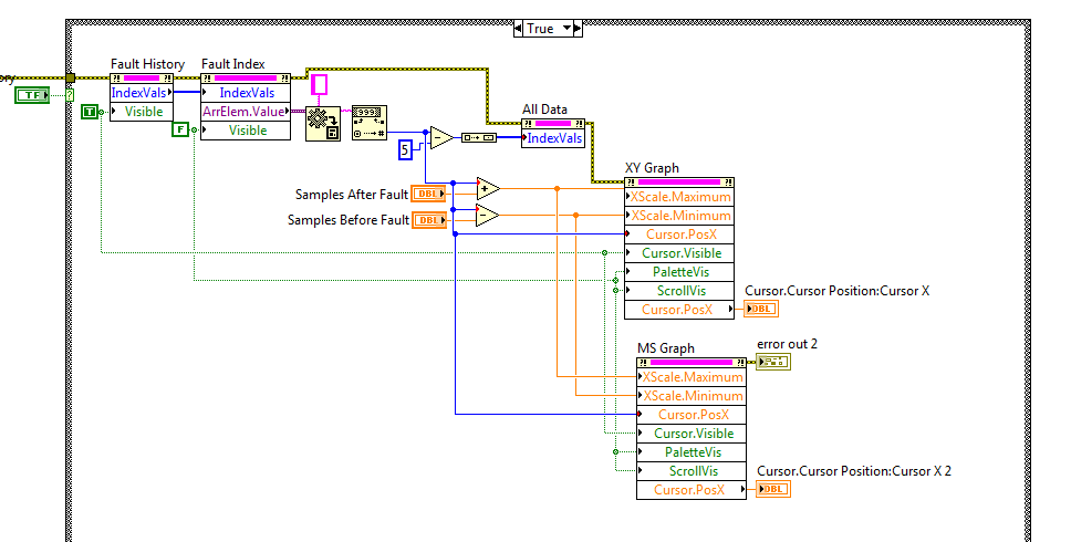
Problem with cursor Mixed Signal graphic LV 2013
I'm trying to create a function that puts the cursor at a specific point on the x axis. When I send the value, the cursor behaves normally. When I send the value (even when you use a constant) the cursor will keep oscillating between the previous position and entered the property node.
This will not occur when you use a XY Chart, only with a multi signal. Is this a bug or I'm doing something obviously wrong? Here is an excerpt of my comic.
-
Convert a chart 2D with various sizes for Mixed Signal
Hi all
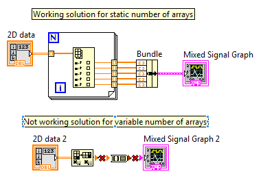
I have a table 2D with, for example, 5 signals with each 100 data points (so a table of 5 x 100).
I want to show each table on a graph of mixed signals. I have a solution that works for this problem (see attachment).
My problem is that the number of signals and therefore the size of 2D array is variable. So the next time I run the VI, the table can be, for example, an array of 6 x 200. In this case I can't show all 6 plots on a graph of signal mixd my working solution.
I was looking for a 'Table 2D to the cluster' function in Labview (see attachment) but unfortunally it is unavailable (perhaps a tip for developers
 ).
).Is there someone who has a solution for my problem?
Thanks in advance,
Patrick
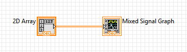
Why can't we just plug them directly together? Mixed Signal graphics take an array as input 2D type.
-
Programmatically formatting graphic mixed signals
I am writing an FPGA application where I am acquiring data from a unit under test (USE). The PXI-7842R digitizes 3 groups of signals:
1. an analog voltage monitor
2. 5 digital signals connected to the analog inputs (limitation of the pinout of the connector) and converted into Boolean values
3. 11 digital signals connected to the digital inputs
That's a total of 1 analog and 16 digital inputs. I want to show them on the same graph, so I used a graph of mixed signals.
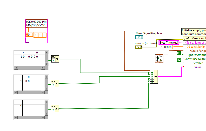
To avoid reconfiguring the graph of mixed signals, everytime I open the app, I wrote a Subvi to programmatically format the chart. I pass a reference to the graphic indicator of mixed signals and try to adapt it to look how I want. The indicator has been designed as a cluster of analog waveform 1, 2 bus waveform Digital 5 signals 1 waveforms digital bus 3 and 3 different digital waveforms. The Subvi is called inside the host VI using a statement box controlled by the 'First Call' function. Then host vi bed a U32 to the target-to-Host DMA FIFO, formats the data in the correct order and the beams while an indicator of mixed signals. During an attempt to format the chart programmatically, I get errors in property not valid which seem to depend on State. Unfortunately, the documentation of the properties seems to be quite uneven for errors I get. The Subvi attached through the following sequence:
1. configure the shared axis and shared properties (IgnoreAttributes, ShowBusseswithLines)
2 set up the area of tracing analog scale Y (superior plot, area 0? documentation is inconsistent on this point)
3 set up the area of tracing digital scale (sector 1) Y?
4. name the digital bus (3 in total, should be numbered 0-2).
5 name the plots
Correctly all steps 1 through 3, but I get an error when you try to set the Active Bus to 0--> ' #1077 Error, invalid property (Bus Active)»
I tried to set the Active plot area to 1 before setting the bus, and I get the same error.
But then sometimes if I rerun the VI host without change, the Subvi ends correctly (even if the area of the scale becomes huge and empty). The only way I can remove the errors is to set the for loops to iterate 0 times, allow the host VI run a few cycles, stop the host VI, remove the constants 0 and run again. And then there is no property errors.
I then tried to create a constant of mixed signals with the correct sequence of the empty slots and it allows to set the MixedGraph::Value property at the beginning of the Subvi. Now error #1077 occurs at the level of the active node before Plot Bus Active node. The thing first on the definition of the constants of iteration 0 does not help when the value property is an initial value.
Here are my questions:
1. the ActivePlotArea property must be configured to use ActivePlots or ActiveBusses, or is that only for sizing and moving areas of land?
2 - is ActiveBus ActivePlot to define first of all necessary to property? for example, if I have ActivePlot = 0 (for analog plot), the ActiveBus property will always fail?
3. what else is necessary for the property ActiveBus of function call?
4. why the Subvi is failing the first time but succeed during subsequent calls without be initialized does not yet reach every time after you initialize (except for loops are set to 0 and Subvi finishes once)?
5. because I show a legend of the plot, I don't want the names of digital signal appears again in the scale box Y. How can I hide the names but to allow the plot area to extend completely to the legend of the plot rather than leave a large area of wasted white space?
Hi Nick,
The reason your Subvi does not work, it's the bus you want to change do not exist when you run.
If you want to run this sub - VI like initializer, you must first initialize all of the plots you will be change.
I've included a small example of how to achieve this by grouping together a constant of analog waveform with some constants of digital waveforms and food nerd in the property "value" Mixed Signal curve.
-
How is - I size the Group zone oin the graph of mixed signals to meet my signal names?
I have a graph simple signal mixed and I programmed my signal names and they are longer than the width of the component group existing on the subject, and I want them to be visible. How can I resize the graphic components because I wrote the names to the object? I know that I can personalize the thing, but y at - it a method or a property that I'm missing here?
It seems that it is a known problem. You can change the size of the legend by using a property node for waveform graphs, but not for a graph of mixed signals. A good work-around would be to right-click the gray bar between the legend and the plot area until your pointer changes to the resize tool. You can then size it is large enough to show the whole legend. It is a question that is configured to be resolved in future versions of LabVIEW.
-
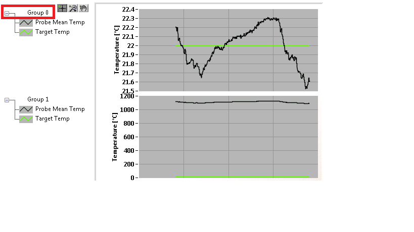
absolute time in the chart of mixed signals
I am trying to build a chart of mixed signals with 4 inputs (Temp, Temp setpoint, % RH and set RH %). I want the X axis to be absolute time, but do not know how to wire properly. To search the help files and discussion forums, I think I should include a timestamp as a DBL. So far, I have created 3 scenarios:
- All of the lines of work but x 4 entered is relative.
- Two main lines of work and entered x is absolute time (below)
- Even with 4 inputs graphic breeze with an error that the number of entries in cluster does not match (away). ???
I seem to be missing something basic. I would be very happy to anyone help... until the computer gets!

PS LV8.5/WinXP Pro


There seems to be a problem with the time of the x axis when you enter analog data tables and the waveform of digital data. Try the attached vi where you are piping the analog data as waveforms. Allows always to look at the data as it is collected over a period of time, which is what it seems you are trying to do. It also has a clear function. My example is rough; It would probably be best done with loops producer-consumer or one event loop to make it more effective. Let me know if this does not work.
-
plot area chart mixed signal displayed
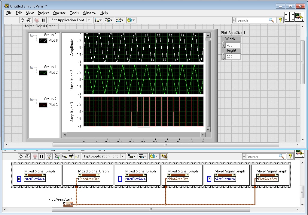
I have a graph of mixed signals with 2 areas of land and am trying to optimize the flexibility with the screen space and look at a. Sometimes I want to see the two draw areas in display at half the height of the graphical display of any mixture GIS and sometimes I need better display resolution that makes me want to make one of the plot areas fill the full graph of the display area and then simply scroll down to see the other.
What is the best way fo doing this if I want to press a button to easily switch between these 2 views? Use display port size and properties limits or something else? (The properties of ports and view limits are not well-defined dimensions of what I can find either)
Hello
You can do this by using a combination of several nodes of property. You can use the PlotAreaSize property to manually set the size of the individual parcels (not the viewport). Note that you need to use the ActPlotArea property to enable each parcel before resizing. After you set the size of the plots, set the size of the window using the window-> size-> all the items property.
I advise to use a structure of the event to change the properties when you click the button to toggle between the two views.
Hope that helps.
-
mixed-signal graph size automatic
This seems simple, but is there an option that will automatically format all the graphs on my graph of Mixed Signal to the size of my VI? For example, if I increase and decrease the size, the graphics remain a constant size and I would scroll to see them. Secondly, that all graphs have the same vertical height, instead of me manually by dragging the separator to try to make all equal in size?
Right click possibility and also space all the graphs and auto fit all graphs would be very practical! I can't find the option for her.
Image attached showing the spacing I'm talking about.
Thank you!
Hello
This can be done programmatically with the nodes property. The trick is to use two nodes of different property of the to do.
We must first define whatever parcel we want change to be the active plot by using the Active plot area property node. We can then define the limits of this plot by using the node property parcel size of the area, which is located under plot area > size.
Good luck!
-
How to dynamically add a plot to a graph of mixed signals
I have a graph of mixed signals where I'm plotting a signal from a time axis. I'm trying to dynamically add a second plot to this graph against the same time axis (with a different scale of Y), but when I built a 2D array and try to connect in the graph (using a local variable) I get an error of size mismatch. I know for sure I did in the past (cable tables with different sizes for a same MSG) with no problems but, today, for some reason any I can't solve this problem.
Am I missing something?
Yes, you're probably writing a table 1 d somewhere that is causing to accept only 1 d. To address your problem above, just put a table node build in whenever you have a 1 d table and it will be just a 2D array with a single line of data.
To add a field to your current locations, your screenshot above should work once the plot knows that he has to accept the 2D tables.
Reading from a local variable, change something and then write about it once again can lead to a lot of issues down the line. Race conditions are a pain in the butt, so get rid of that sort of thing is good to do from the start. I didn't know the rest of your code, so I don't know how you treat it, but just keep in mind that you add to your software.
-
Mixed signals with the buffer graph.
Hi I'm new to LabView and I have a really basic question.
Here's what I'm trying to do.
1. I use chart of the mixed signals to display some acquired DAQmx signals.
2. I have 3 separate field areas.
3 X - axes of these areas of land must be completely in Sync.
that is the main reason why I want to use graph of mixed signals.
4. I want that signals are displayed as table of waveform,
It's the waveform data are not deleted during update
and I can scroll to watch old stuff.
5. I also want to save the data as numbers of I can also
do all sorts of calculations with them.
Now with my vi, the graph gets refreshed and crushed
each sampling period and only a small fraction of the data I want is
shown on the screen. (I want to these fractions to get annexed by)
order of chlonological...)
I guess that it is a fairly common problem for a beginner.
I could easily do in C or Java, but rather difficult to do on the GUI.
Any help will be appreciated
Thank you!
If you want to see the temporal evolution of your chart, simply change the x-axis not autoscale under properties of the graph. You can use align your waveform in programming > wave > align times. You can activate the option to scroll by right clicking on the graph > visible elements > graphic palette.
There are many options for data backup. The quick and dirty is to enable indexing of your time loop and thread to write on the worksheet to the title of programming > e/s file > write in the spreadsheet file. Keep in mind that the file is a txt file.
Post your code for help.
-
Control chart and mixed signals tab crashed for LabView 2009
I find a serious problem by using the chart of mixed signals with tab control. Two examples and detailed drscription are attached. In TestMix.vi there is mixed, graphics and additional code to display the data. Normal execution of the program. I add the tab control and move the graph mixed signal in Page 2 (see TestMix2.vi). After registration as TestMix2, close the vi and oppening is façade of LabView frozen after touching on page 2 of the tab control.
Does anyone have the solution for this case?
Best regards!
In his stavljanjem digitalnog dijela na kraj grafa sam otkrio kao slucajnost, ali only Monte puku is tako I dolazi zaobilaznog rijesenja.
Kada dobije informaciju od kolega bi bug mogao biti rijesen obavijestiti cu spomenuti kada go! Moze biti u Drugom.mp3 od nadolazecih patchova ili u sljedecoj verziji LabView eventualno - a.
Srdacan pozdrav
Franjo Tonkovic
-
ClickListener in ADF graphic line
Hello
Is it possible to have the values of the axes x and y (i.e.coordinates) of the graphic line if the user clicks in an area of the line between the points (not the point itself)?
I can get the values of the axes x and there if I click on the point on line as follows:
public void graphClickListener (ClickEvent clickEvent)
{
ComponentHandle handle = clickEvent.getComponentHandle ();
If (handle instanceof DataComponentHandle)
{
DataComponentHandle = (DataComponentHandle) handle dhandle;
Object Val = dhandle.getValue (DataComponentHandle.UNFORMATTED_VALUE);
Date timeVal = null;
Attributes [] seriesInfo = dhandle.getSeriesAttributes ();
If (seriesInfo! = null & & seriesInfo.length > 0)
{
Object = seriesInfo seriesName [0] .getValue (Attributes.LABEL_VALUE);
Attributes [] groupInfo = dhandle.getGroupAttributes ();
If (groupInfo! = null & & groupInfo.length > 0)
{
TimeObj = groupInfo object [0] .getValue (Attributes.LABEL_VALUE);
If (timeObj! = null)
timeVal = new Date (((Date) timeObj) .getTime ());
}
}
However when I click on one area of the line between the points (not the point itself) I can get only the information series, not axis x and axis are name value:
ElseIf (manage instanceof SeriesComponentHandle)
{
Get the attributes for the series
Attributes [] seriesInfo = ((SeriesComponentHandle) handle) .getSeriesAttributes ();
String data = "";
If (seriesInfo! = null)
{
for (uploading Attributes: seriesInfo)
{
data += "\nSeries value:"+ attrs.getValue (Attributes.LABEL_VALUE);.
data += "\nSeries name:"+ attrs.getValue (Attributes.LABEL_ATTRIBUTE);.
data += "\nSeries id value:"+ attrs.getValue (Attributes.ID_VALUE);.
data += "\nSeries name id:"+ attrs.getValue (Attributes.ID_ATTRIBUTE);.
}
}
System.out.println (Data);
}
}
Here is the source of the jsf file:
< dvt:graph id = "lineGraph1" animationOnDisplay = "auto".
tabularData = "#{pageFlowScope.gaphPageStateBean_backing.graphTabularData} '"
customToolTipCallback = "#{pageFlowScopegraphPageStateBean_backing.callback} '"
graphType = "LINE_VERT_ABS."
seriesObjectCount = "#{pageFlowScope.graphPageStateBean_backing.seriesCount} '"
timeRangeStart = "#{pageFlowScope.graphPageStateBean_backing.graphStartDate} '"
timeRangeEnd = "#{pageFlowScope.graphPageStateBean_backing.graphEndDate} '"
timeAxisInterval = "CTAI_MINUTE" timeRangeMode = "TRM_EXPLICIT".
"partialTriggers =": commandLink1: t1:cb7.
Binding = "#{backingBeanScope.graphPageBean_backing.graphBinding} '"
clickListener = "#{backingBeanScope.graphPageBean_backing.graphClickListener} '"
timeAxisType = "TAT_IRREGULAR" textAntialiasing = "true".
scrollListener = "#{backingBeanScope.graphPageBean_backing.scrollListener} '"
zoomListener = "#{backingBeanScope.graphPageBean_backing.zoomListener} '"
markerTooltipType = "MTT_VALUES_TEXT" >
< dvt:background / >
< dvt:graphPlotArea / >
< dvt:seriesSet defaultLineWidth = "3" defaultMarkerColor = "#ffffff".
seriesMap = "#{pageFlowScope.graphPageStateBean_backing.lineGraphSeriesMap} '"
markerDisplayed = 'true '.
defaultMarkerShape = "MS_CIRCLE" / >
< dvt:o1Axis id = "rhrhtr6" scrolling = "on" / >
< dvt:y1Axis id = "fwef43" lineWidth = '1' axisMaxValue = '1.0 '.
axisMinValue = "0.0" logarithmicBase = "10" / >
< dvt:legendArea automaticPlacement = "AP_NEVER" rendered = "false" / >
< dvt:o1TickLabel id = "o1TickLabel1" tickLabelSkipCount = "50".
tickLabelSkipMode = "TLS_MANUAL".
tickLabelSkipFirst = "0" / >
< dvt:y1MajorTick id = "y1MajorTick1".
tickStyle = "#{pageFlowScope.gaphPageStateBean_backing." YAxisTickLine} "/ >"
< rendered dvt:y1TickLabel = "false" / >
< dvt:shapeAttributesSet id = "shapeAttribSet1" >
< component dvt:shapeAttributes = clickable 'GRAPH_AREAMARKER' = 'true '.
ID = "shapeAttrib1" / >
< / dvt:shapeAttributesSet >
< dvt:timeAxisDateFormat timeFormat = "HOUR24_MINUTE."
yearFormat = "YEAR_LONG."
monthFormat = "MONTH_SHORT."
quarterFormat = "NONE" / >
< dvt:o1Title text = "" time: "horizontalAlignment ="LEFT">"
< dvt:graphFont id = "graphFont1" emphasized = "true" color = "#002173" / >
< / dvt:o1Title >
< dvt:annotationSet annotationMap="#{pageFlowScope.graphPageStateBean_backing.graphAnnotationMap}"/ >
< / dvt:graph >
Thank you.
Valon
JDeveloper 11.1.1.5.0
AF:graph
Except if a function is used to interpolate the data points, is not possible.
-
Vertical dotted lines and bad shading on Satellite P30-109
Hello
Sorry for my bad English,
I have a problem TFT on my Satellite P30-109.
Regular vertical dotted lines and bad shading.
I formatted the disk with the recovery disk, but nothing has changed.An irregular viewing is present during windows startup.
What can be?
Have you any suggestions? I have to throw my PC?Thanks for your help.
StefanoChain is quite right. If the same thing happens on an external device there is problem with the video card and probably the whole motherboard must be exchanged.
Sorry, but you must contact partner authorized in your country. If you need address, you can find them under http://www.csd.toshiba.com/cgi-bin/tais/su/su_gaspLocator.jsp?pf=true
Good luck!
Maybe you are looking for
-
Open an email from file directly from the screen of composition
Hello! I use a system here in my business that generates an automatic e-mail and prepare it to be sent.We were using MS Outlook and we migrated to thunderbird for many reasons. But since it has migrated, the system cannot generate this email on the f
-
How to I enlarge the fonts of the sites permanently (without the zoom in function)
I'm working on a 27-inch screen and I constantly zoom in to read the content. Is it possible to enlarge the fonts loaded by firefox Web?
-
Firefox not sites load. The charging symbol still turns but nothing happens. No problem with Safari
Since one day Firefox cannot load Web sites. It takes about 5 minutes to load a site.But I don't have the patience, so I use Safari, which works well. but I prefer to use Firefox
-
Windows driver 8 - switchable graphics problem
Hello I installed Windows 8 RTM Enterprise (trial) on my laptop HP G62 B13SL . It has an ATI Mobility Radeon HD 5470 and an Intel's HD Graphics (Core i3, first generation). I installed the driver ATI Catalyst 12.8 (with Win8 compatibility). During th
-
Can I use Windows 8 in my current computer?
I have an old computer with xp. I ran a check to see if my computer would except windows8. He failed. I have all my information on the discs in the case of a computer crash. I have a program that completely erases the hard drive. I would then be able