Modbus
Hello
I'm new to Labview and am currently writing a code in Labview and I the Modbus communication protocol. I want to be able to send messeges through labview code and ask the inverters, which is connected to the PV modules, for give me data and he just send me the data. This will be a RS 232 communication.
Where should I start? Please let me know if you know something about it.
Donya
Both ends enough to define the same thing. For the physical connection, you need a null-modem (tx and rx exchanged) cable.
Why would anyone use series for communication between 2 pc instead of an ethernet connection?
Tags: NI Software
Similar Questions
-
Hi all
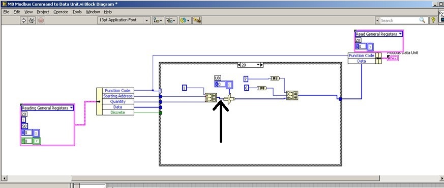
We try to add 20 saving file read function code in order to read the brief in bulk from PLC. We used the modbus for Labview library to communicate with the PLC with Modbus TCP/IP, but when I addes the code function 20 to the cluster of the MB Ethernet Master query entry reading registry Palette entry, the program displays an error. I'll be really appreciated if someone could help with this problem!
We hope all have a good weekend.
Best regards
Sophie
Actually... that is a constraint on the second entry to "build the table? ' It is difficult to tell from the image. If so, what is the data type of this cable?
That must be an array of U16s, because the "quantity" and "home address" are U16. However if the value '1' is a larger data type as U32, labview perhaps at upconversion of the whole table that would result in a larger data set than expected and could cause error 2. You can check on this?
-
Is there a way to read only a modbus on request? I want to be able to click a button 'Get Data of the controller.
Also related, I just want it write on command. I currently have a trigger/relay for writing data, but I can't tell if modbus is always send the "write" command (using the previous value of the line) or not.
I'm reading through the modbus test data. It seems that additional orders would limit the sampling frequency, leading to lost data. If I read that data registers, the data have no recurrence. With other commands, I get up to 10 blocks of the same value.
Thank you.
You take the input module in a relay with option of data block. Only when you raise the output of the command, you will be allowing the flow of the module.
This average thagt unless you trigger the relay, the module will not process and ask for value
-
invertek modbus communication by car
Hi all
Seems modbus is a way to communicate with the disks for a long time. For me, and because we have a new machine equipped invertel drive P2 is new.
So, after many emails between invertek I couldn't so much as to communicate with the reader with their software. Only her entry to go to modbus.org
For their software, I use a converter usb rs485 and I use pins 4 and 5 (pc connection), but for modbus change for 7 and 8 (modbus)
Join is the manual for modbus for the driver.
My question is, what is the easiest to read VI (for now) of records and the way to the entrance. I need to input 03 (for reading), then the registration number?
Please help for the first step, then I'll build the complete software (I have now installed modbus library)
Thanks in advance
cpalka
-
ComBox MODBUS - difficult to write in the registers of the S.R.I.W.
Hey guys,.
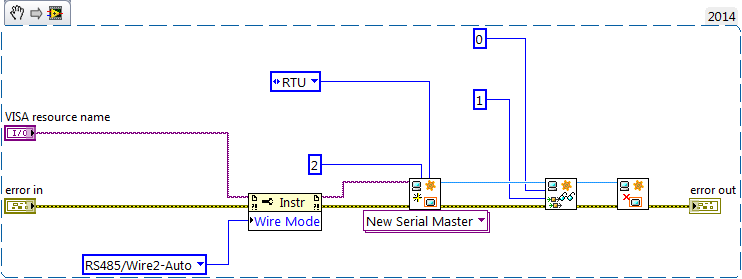
I'm talking to a UPS (ComBox XW +) via MODBUS TCP. I can read the values of read only registers very well, and they line up exactly what I see on the interface of the web page they have. However, when I try to write a particular register r/w, I get an error of the incompatibility of function (-538172 using modbus smithd API). Also, when I try to read the register R/W, I always get the value 65535. This leads me to believe there something wrong with my configuration of device, but just in case, I thought that I would make sure that I wasn't doing anything weird in the code. Please the the image of the block diagram, as well as the manual that I use for the device in the attachment.
There is a small note MODBUS online as well:
http://solar.Schneider-Electric.com/wp-content/uploads/2014/04/conext-TL-using-Modbus-application-No...Hey Thomas!
Thanks for your help, however, this link is not available more when I try to open it.
In any case, this problem is resolved. I was just writing the bad slave ID! The other slave was present on the network, but it is card MODBUS is completely different, that's why I was seeing these weird values.
-
How can I change the address Modbus to Modbus IO server programmatically?
Hi experts,
I use a cRIO 9076 that is configured as a server IO slave Modbus to Modbus TCP communication. I have always used the same Modbus address to configure the server of e/s and it has never been necessary to change so far. So I was wondering if there is a way to change address Modbus IO server programmatically, after it has been initially configured?
Thank you
Volker
Hi Volker,
There is an Express VI, that lets you create or change existing servers of e/s Modbus programmatically createand configure the Server IO. Once you set up like Modbus, you will be able to provide the address programmatically.
In regards to the address - you are right in that the Modbus address configured in the configuration of the server is not really used with Modbus Ethernet. According to Modbus specifications, the address is used when a network connecting Modbus Ethernet to a secondary network series Modbus via a bridge or a bridge. The specs say that the address 0xFF should be used on an Ethernet network. For more information on this topic, Please see page 23.
Hope that helps!
Best regards
-
Control data DATAKOM DKM 409 RS485 modbus output
Hello world
My project is to control a furnace and im using DATAKOM DKM 409 with rs485 modbus output. in this project, I want to monitor data using labview. reason to do this, I use a RS 485 to RS 232 converter but when I connect them to each other and to my pc there is no recognition of the machine and when I want to use visa in BT it cant recohnie any device connected to it and gives me below error:
LabVIEW: (Hex 0xBFFF009E) VISA or a library of code required by VISA impossible situated loaded. This is usually due to a required driver is not installed on the system.
my converter is under this link:
http://www.securitycamera2000.com/products/CCTV-RS232-to-RS485-PTZ-converter-for-DVR.html
Please give me a guide about what is not going in my project. I really don't know why I can't config my port of visa and my source of visa is not recognized
thnks
ERFAN Shahsavari
Hello my dear all
Here is the answer and the consequence of my work:
1. in the manual of my legacy notes that we can choose 1 to 253 device id and I chose 240 but it was a mistake and I have the device between 1 32 ID value. (If I want to select more than 32 a Repeater must be used)
2. According to the operating instructions register addresses are between 40001: 40095 example 40068 and because of the structure of MODBUS RTD (device id, the function code, address of departure, number of registers to read registry, control CRC) I need to set the register addresses 40068, but it was a mistake and it was bad. The correct registry address is 68 no 40068. And in the structure MODBUS should I use 68 no 40068 or using the modbus library, that I must use 68 as registry address 40068 not.
Thanks for your guides
-
Hello Forums or
This is my first post on this forum and I've been using labview for about 8 months now
I have a problem about writing data in the modbus registers through a server of e/s defined as a slave modbus for my hardware 9074. Once I finished the project of construction and deployment of the variables and by following the instructions here , he reports no results but a row of zeros. I have the DSM nor opened and configuration modbus master to see whether the data is actually read or written on the respective sides that give the same line of zeros so. What I am actually trying to write is a single-precision floating data table. The registers are structured F40000-F46534 runs from 10 items or have them for range AF40001L1-AF46534L1 of the AF40001L10 point where it's an array of length 10. (Referenced beaches here)
I know 1 thing for you, the modbus connection works and is ready for data requests, I tested cela NI DSM and set manually the data for and received my master.
System and project specifications
Windows 7 operating system
LabVIEW edition development system complete 2011
No module Labview DSC, but I use the real time such referenced by one of the documents
This project is an application in real time with fpga mode (and not scan interface)
The master and the slave are the same network and subnet
Connection Modbus type: TCP
9074 compact slots rio 8
9234 module x 3
module 9221 x 1
9472 module x 1
Engine service Variable shared running on windows os and rtos system
Used this guide to learn more about the Protocol modbus, as I have searched all over the internet to learn more about modbus
I already have software Modbus IO Server installed on the crio thanks to max or 1.8 for NI RIO 4.0 version
file attachment (s)
Image of software specifications Crio
Image of data written in scheme-block rt variable
Short version of the problem: why is the e/s no variable writes in with the converted correctly data?
Okay, Yes, it's that I was the one proposed. Regarding the news of the error, if you look at the bottom of your image to DSM, you see a little commfail and an error code, but it seems that those are OK.
The only thing I can think is that DSM (or another function) is written for a range of values that includes 400004. I suggest you to put into service 4-going to a range of 3. 3 s are entered only (perspective control), then you can be sure that the master is not trampling on the data. Once you have checked that, look at DSM and any other code running to make sure q EU not accidentally write 0s to the same reg.
-
I have a Modbus (VP Flowscope) instrument that I'm trying to interface with and I've never worked on before Modbus. I wanted to see if anyone had some tips to get this working soon.
I wrote the code using the NI DSC, the code on the NOR-Lab Toolkit (which is roughly the same as the DSC OR) and another download which can be found here:
http://www.NI.com/example/29756/en/
All of them fail with my setup, even if I think I can see a response from the slave device.
Attached are a few snapshots of my code and a screen shot of what I see on the oscilloscope. On the ground of the scope, I think that the second operation is a response of the slave, because if I change the settings (address, parity, etc.) then I do not see this transaction.
I got this job with the 1.2.1 MODBUS library, where you can dive into the code and see the bytes sent/received.
Once I realized my bytes sent were the same as what I saw in other programs, after a bit of work to clear some false errors (reading 00 what from VISA read IO error exception), I could see the bytes received were the same institutions.
-
Analog value read with DSC Module Modbus
Hi, I have a Delta PLC with an AD converter module. I use the four analog channels and in one of them, I have a thermocouple which displays temperature data on a microprocessor thermocouple meter. However, I want to display the data in Labview. The controller communicates with labview through the DSC Module of labview with success, but I am not able to read the data. Looking forward to your help.
Found the solution. addressing to the modbus master was different for this model of plc, so I looked up the address for delta plc Modbus and the analog read list has been a success on labview.
-
Power Meter Modbus rs485 via 9871
Hello
I'm under Labview 2015
I'm currently trying to connect has the place D Pm820 (meter) NI 9871 module in a crio 9076. The project is supposed to read the performance data in the registers of the meter (current, voltage, etc.) using the port rs485 on the back of the meter.
The pm820 has a pinout for rs485 2-wire with 1 (-) 2 (+) and a 3rd Armor/ground wire. The pm820 meter is a slave device that has several different protocols that it can run on (Modbus RTU/ACII8/7 and JBUS).
The setting of the counter are:
Protocol: Modbus RTU
Address: 1
Baud rate: 9600
Parity: None
I use the module 9871 for device communication for the cRio
I use the power cord that came with the module 9871 RJ50 to db9 and have the pins 4 and 8 rider (TXD + TXD +), and then connected to the (+) 5 and 9 meter jumper pins (-RXD, TXD) - and then wired to the (-) meter and ground on pin 1. I have read, it's how wire you the db9 connection rs485 2-wire.
My first goal is just to get the communication with the power meter so that the value that I see in the registry, it is what I should see.
I started using an example VI for holding registers (master modbus on target RT) reading as labview was pre-constructed and changed it so that its contribution would be to port 1 on the 9871 as created controls for my run configuration. Other I left the rest of the VI that it has been opened.
When I run the VI I see numbers appear in the registry list, but they have nothing to do with the power meter. I unplugged the power meter and still got the same result however if you unplug the cable connection the 9871 1 VI will be a mistake (as expected). I have the feeling that the labview speaks to itself through the 9871, but I'm not sure. I looked at other posts, trying to find a solution and came across a mention of having to set the thread mode, but I can't find a way to do it using the modbus library. However I could not find an example reading VISA registers the using visa I see there is a way to do it.
I enclose a picture of my VI and the front panel to show what I mean.
If I could help either make my VI work or at least get pointed in the right direction that would be great. I'm not against the use of the Visa library either. Also if you have examples or resources that would allow that they would be greatly appreciated
It's just a part of my project but just get work communication is my main priority at the moment.
Thanks in advance,
Mike
-
I have a sending oven that uses the Protocol No. 3, which communicate using Modbus over RS485. I use the Modbus Library, I found the Forum and I'm still with the controller communication disorders. I use a USB RS485 converter and my converter is set to half duplex 2 wire without echo. I'm able to convey, but receives a message back from the oven. Does anyone have any experience or any idea on how to use LabVIEW with this equipment?
I thank you for your response, we found the problem and the oven came to us by cable to the rear, this is why we could not communicate. We communicate now

-
Exstance no of Modbus communication
I work with a rs232 for connection rs485 via a UNO2019 PC box. The RS-485 connection is going to be MODbus RTU, has about 4 slaves on the bus (MMI flowmeter, VFD, two temperature RTD). All theses devices are configured accordingin
9600 baud, odd parity, no flow control. the VISA resource would be COM3.
Now all of these components I worked with every day for numerious months. and VI implementation exists (almost) without error. I get an error code for the additional bytes to the port, but he spends the whole upward. I don't know if I'm not or write, but it has happened in every piece of software, I developed in labview (it does not check the boolean error so I guess that's not important).
Currently, when I try to read the registers of the MODbus slave, I get error:
-107380733 (that mean 100 different things that I have done my research properly, bad bytes to the port, do not use correct end characters in your message). But every time I have seen that error code discussed in question direct USB/RS232, not RS232 to RS485.
The attached string was
3-> MD series Master Query.vi
2-> MB series Master query Holding Register.vi
1-> address Test.vi
Thank you for any light you can contribute on my problem.
Problem has been resolved. It was a hardware problem as I thought. Apperently this code error will exist when your RS-232/485 is hard set via dipswitches do not send data.
-
Point of Modbus DSC read does not correctly
I use 2013 LV 32-bit on W7 64-bit. I talk to an industrial controller with Modbus to Ethernet. My current software uses the interface modbus DSC, in which I define the bus Modbus itself within a library in the project, and then set each point Modbus as an address within this definition of modbus. Inside LabVIEW, you can then get the data Modbus via shared Variables. I am currently using the dynamic variable calls shared, rather than static variables shared. I have points that are Boolean (coils) and real, with a read-only and a read/write. In general, it all works.
However, there is a real read/write that acts funny. If I put a new value, or the industrial controller assigns a new value, the industrial controller Gets the new value. Variable motor shared on my computer gets even the new value, as can be verified by opening the Distributed System Manager. But LabVIEW continues to read the old value, without error. Other points of read/write work very well, and I have looked on the definition of the address several times and cannot find any reason why this should be different than the others.
Does anyone have any ideas why DSM sees a new value of a shared variable, without LabVIEW continues to get the old value? I watched the init for the dynamics of SV case, and I see all the options I can change to try to solve this problem. My next attempt will be to rewrite the entire auxiliary system so that it uses the most recent Modbus Library of NOR and ignores the whole thing of DSC. It will be probably much better for other reasons as well. I noticed that with DSC and the shared Variables, the first time that the program runs it starts fairly quickly, but subsequent executions can take up to two minutes to connect to the SV.
Thank you
DaveT
Never mind. I think I found the problem. A bug minor configuration in my own code...
-
I have to work with labview and modbus.
I wud would like to know what are the additional elements required to use modbus.
I use labview 8.0.From where to find the appropriate modbus library.
I downloaded 8.2 modbus... but were getting BSE errors of the incompatibility of the version of labview.
Pls let me know what is frmn where I can download the modbus for labview 8.0 library
Thanks in advance
Download you and watch in the ni_modbus_1_2.zip?
There is a directory of files of version 7.1 in there. You will be able to open those of 8.0.
PS. You can use the spell checker. The correct spelling of a 'cudnt"is"couldn't ".
-
with boredom Watlow PM 485 modbus communication
I have a PM Watlow I see now at MAX and using EZ area code can get info manufacture of. I also uses the Modbus in the add-on on Saphire series tool to try to write or read anything from him (for the first time) and I always get an error of 'time' out of the slave. I tried to make a simple reading of VISA I found on some positions, and I get the same timeout error. It seems that if I try something Labview I get this error. I even tried writing Hex to the thing with the same results. Can anyone throw me a BONE?
There are a couple of free libraries.
Maybe you are looking for
-
Firefox 7.0.1. Windows7 Pro 64.Yesterday I was streaming audio of sky.fm and noticed that the back navigation toolbar arrow no longer and that he has failed since. FF restarting, rebooting the computer, same problem. Private browsing has never been u
-
Tip: Faster boot Windows 7 and Vista
By default, Windows Vista and Windows 7 dΘmarrez with a single processor. If you have a multi-core PC, you can change the number of processors used during system startup. Speed will be improved a bit but don't expect wonders, Do it like this: 1. open
-
Quicken uninstalled after Windows Update
After running Windows Update and install the updates, I discovered that Quicken software I had installed and used on my PC has been uninstalled. My OS is Windows Vista PremiumAfter installing updates with Windows Update I couldn't see Quicken to cont
-
Photosmart 7525: Printer cartridges
I bought a set according to market my local bestbuy printer cartridges and it seems that for some reason any, my printer does not print text documents, I went to costco and bought a new set of cartridges hp every 5 and I was wondering if it was possi
-
Inspiron N7110 processor upgrade
Hello, I have the 2350 M processor i3 and I was wondering if it is possible at all to switch to an i5 or an i7.I saw one being dismantled, and it looks like he has a half-bridge cpu.