Modulation of pulse in USB OR-6225
I'm trying to modulate the frequency and the amplitude of the pulse coming out of that Board's PFI lines. Is it possible to change the amplitude of the pulse?
I understand, the TTL digital logical values
Tags: NI Software
Similar Questions
-
With the help of modulated signal pulse width (square wave) to control when a signal is enabled or disable
Hello all
I am using a modulated signal to labview created pulse width (square wave) to control when a signal is activated or not.
Here is my logic and a concrete example:
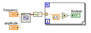
(1) the wave source signal is continuous
(2) use a PWM (square wave) created in labview to control when the signal is enabled or disabled
(3) if the PWM (amplitude) signal is superior to 0 play signal PWM is not greater than 0 do not play signal.I use actually this to the sequence step / pulse several distinct magnetic coils using my audio card (which has several channels of audio output), I have a signal in labview played constantly. As to compare it to the PWM (square wave) which controls whether or not the signal is played on each separate channel. That way I can control which coil is on and offshore and in what order they are activated.
I couldn't find an edge detection for a square wave created in labview, so I tried the limits, but it doesn't seem to work unless I change the phase manually and it only goes 1-1. I'm just trying to compare the PWM (edges of the square wave) already created by labview / play a signal if the pulse is greater than 0 and it shuts off the signal, if she is less than 0.
Should I do this another way
TIA
A waveform contains an array of values. You must check every value and respond accordingly:
-
Hello
I use a mx-acquisition of data (NI USB-6211) and I would like to use it to generate a pulse of digital modulation
that is triggered by an analog input signal. The input signal is a pulse of squares analog modulated
What is almost periodic. It's because of my set up, and I can't do anything with it. I would use the
before the edge of this signal to trigger the production of a digital pulse signal modulated (0-5 V). My
problem is summarized in the figure given in the annex. I would also like to have the possibility of
Configure the 'backwardness' and the term of "TAU_LED", while the VI works.
I have looked at several examples of instrument OR meter generation, generation of PCI I / AO, but doesn't
not managed to solve my problem. Does anyone have an idea of how start with my problem? Are there
No matter what example VI that I could start to change?
Thanks in advance,
Gregory
Hi Gregory,
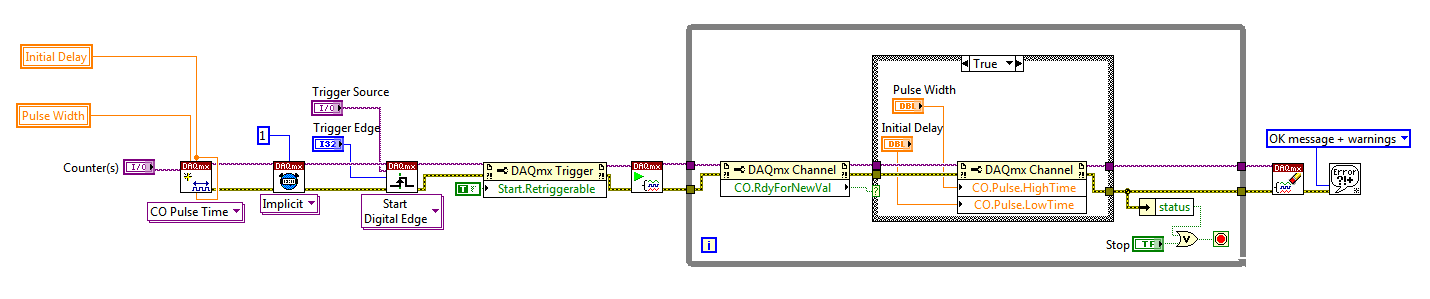
Sorry I forgot to mention: the Initial delay applies only to the first impulse of a redeclenchables generation. Every subsequent impulse will use low time as the Initial delay. I agree the behavior is not very intuitive (our latest guidance of series X actually supported an Initial period to allow on property Retrigger), but it is described in this knowledge baseand should also be mentioned in the DAQmx help.
As you generate just a single pulse, I would recommend simply connecting the Initial delay and at the entrances of low time to the same value for each pulse will be delayed further.
Exit tasks ongoing counter currently supports DAQmx writing. However, the finished generations or simple impulse are not. However, you should always be able to get the behavior you need with a property node DAQmx. The current solution on the series E/M is:
Again, this is not the most intuitive, but I checked that it works on my 6210. After writing a new value in the software the pulse will be updated on the 2nd trigger. Attached is the code stored in LV8.2.
Best regards
-
Pulser for usb-6218 with exponentially increase
Hello, I have a USB-6218. I need to check 2 stepper motors which take
dev1/ctrl0 / dev1/ctrl1 signal for speed, A01 and A02 for the
direction (forward and back). I need to send a signal of 5 volts
square wave to control the direction with a frequency chosen by the user on A01 and A02. I also send a series of pulses
with fixed amplitude 5 volts and frequency select by the user. impulses must be
Envoy with frequency increasing exponentially with the frequency 0
chosen by the user. How can I do? Thanks for your helpThanks so much Andrea! I solved
My problem! -
8-bit word per pulse output USB-6009
I need to generate a 8-bit word and a strobe pulse in Matlab via a usb-6009. How do I do that? Any help is appreciated!
To answer my own question:
Connect the wires to the digital pins p0.0 - 0, 7 (each represents a bit) and an additional to p1.0 (strobe bit).
MATLAB code:
OID = digitalio ('nidaq', 'Dev1');
AddLine (dio, 0:7, 0, 'Out'); %8 lines on port 0AddLine (dio, 0, 1, 'Out'); Strobe % on port 1
sendthisvalue = 23;
binvec = [dec2binvec(sendthisvalue,8), 0]; % the 8-bit word and the ILO first strobe set to 0
putValue (Dio, binvec);
binvec (9) = 1; bit set strobe 1%
putValue (Dio, binvec);
Initially, I used two separate "putvalue' instructions, set up the word of 8 bits, and then another for the bit of strobe, but the flash has not been received. That doesn't seem to work, it's if I include both the 8-bit word and the value of bit of strobe in each 'putvalue' statement, as in the code above.
-
train of generation of alternative pulse with USB-6251
Hi all
My goal is to generation on the USB6251 signal as output:
http://S232.Photobucket.com/albums/ee262/rusian24h/?action=view¤t=formofsignal.jpg"target ="_blank"" >
http://i232.photobucket.com/albums/ee262/rusian24h/formofsignal.jpg "border ="0"alt ="Photobucket">"


First, I marked VI "generation signal ' (attached fllowing), after that, I replaced under VI"Basic fuction generator"in VI"Multi-Fuction-Synch I-AO"(in the library of examples of Laview) with VI"generating the signal.
http://S232.Photobucket.com/albums/ee262/rusian24h/?action=view¤t=Outputanalogsignal.jpg"target ="_blank"" >
When the program runs, the output signal is last 6 periods of the signal.
How can I output the entire signal?
Please help me
Thank you very much!
Rostov,
Please use the Forums of NOR. I have seen the same behavior that you experience when you place your custom in the AI Multi-multifunction-Synch-AO VI. This behavior is because your personalized VI wasn't out the data you expect. When you wrote your data on you placed him in a graphic waveform and graphics have memory. So he was combining all data in a single chart, even though she was only being written in pieces. That's why when you place your VI in the other program that you saw only the last couple periods. I enclose a VI that I did which will display the step that you are missing, and I used one 'Add waveforms' VI to ensure that all data is saved correctly. If you place this VI in the code you should see everything correctly. Let me know if you have any questions.
I have attached the VI in version 8.6 and 8.0, if you need a later version of 8.0, let me know.
-
Generate a pulse train, NI 9402 modules in cDAQ-9174 chassis
I have two modules NI 9402 in a cDAQ-9174 chassis.
When I output a pulse train on a specific line of the PFI to a specific module, the pulse train is out on the right line of PFI, but on BOTH modules.
I want that the pulse train out only one of the modules.
for example, I select cDAQ2Mod1/ctr1 to output a pulse train on PFI3 of module one. I hear the pulse module one PFI3 train, but I also get it on PFI3 of module 2.
I am also a measurement of separation of two edges with a different counter, but I don't seem to have this problem. (The measure only works when I have the signals connected to the module that I've specified.)
-Paul
This is the Vi I work with.

Hmmm... Looks like it's actually only after I exit a signal on that line. Maybe I should try to clear the line.
-Paul
-
Nice day. I bought a Lenovo y50. and I'm having a problem with do not grasp the memory. and the question is can I set the location "wireless modila. SAMSUNG MINI PCI-E MZMTD128HAFV Msata SSD 128 GB
"'http://m.ebay.com/itm/SAMSUNG-128GB-MINI-PCI-E-Msata-SSD-MZMTD128HAFV-/151756695588?nav=SEARCH ' I can use it as a data bank?" I don't need wifi module, I have a usb wifi adapter.
Mod edit: System model added to the front of the subject line to improve visibility / clarity.
The Y50 does not support storage Msata
-
I have a VB6 program with code that correctly reads the analog inputs of a NOR-USB-6008.
I tried to re - use the code in a module of extensometer OR-USB-9237, but at the stage of DAQmxCreateAIVoltageChan, I get the following error:
"Measurements: physical channel selected does not support the type of measure required by the virtual channel you create."
Create a channel to a type of measure that is supported by the physical channel, or select a physical channel that supports the type of measure. »
Should I call one function other than DAQmxCreateAIVoltageChan?
If so, what is it, or where can I find the reference for these functions?
Or - if it of the right function, should I pass different arguments? Currently, I'll call you:
DAQmxErrChk DAQmxCreateAIVoltageChan(taskHandle, "Dev1/ai1", "", DAQmx_Val_Cfg_Default,-10, 10, DAQmx_Val_VoltageUnits1_Volts, "")
Thanks in advance for your help
-Alas
I thought she 372251a. PDF
Firstly, the correct function is DAQmxCreateAIVoltageChanWithExcit
Second, you can't just ask for a sample single channel - ask for 2 samples instead.
-Alas
-
Hello!
I have a Z61p, and I am looking for a 3 g module. Is it possible to get one for the Z61p? When searching for my type of number on the lenovo site, he claims that there is not, and find info on the series Z seems impossible.
The type number is 0674-KSG.
Martin
I don't think that the z series can be installed with a hsdpa and antenna module, just get a usb or pcmcia version.
-
ESXi 6 - unable to connect the USB device to VM
Hi people:
I have a problem with a specific USB 3 device to try to connect to a virtual computer. The device is a Toshiba USB 3 5 TB hard drive, and it is recognized by ESXi I see when I do a lsusb command, but it is never offered as a choice available to connect to a virtual computer. I tried to restart management agents, restart ESXi with the connected device so that it is immediately detected at startup. I tried using the web client to vcenter server appliance and the native client C. She just never appears as a choice just as if it is not there. Other USB 3 devices, including a Startech gigabit network device and another 2 TB Toshiba USB drive appear as a choice, so it doesn't seem to be a problem with USB 3 devices as a whole. I have connected to other computers and even an Arch Linux VM under the same ESXi which has a Startech USB 3 connected via PCI Passthrough controller and it works in all places. I tried to connect to a USB 2 port just for the heck of it, and I got the same result (invisible to virtual machines) here is what information I have via the newspapers. I see a few entries on the device being suspended in the vmkernel journal, but I don't know if it is normal for a device until it is assigned to a virtual computer.
Any ideas what is wrong or how to fix welcome.
lsusb lsusb [root@naplesesxi:/var/log]
Bus 004 Device 011: ID 0480:d011 Toshiba America information. Systems, Inc..
Bus device 004 008: ID 0 b 95:1790 6 Electronics Corp. AX88179 Gigabit Ethernet
Bus device 003 003: ID 2109:2811
Bus 004 Device 007: ID 2109:8110
Bus 002 Device 012: ID 1058:1003 Western Digital Technologies, Inc. Elements 1000 GB
Bus 007 Device 002: ID 059b: 0277 Iomega Corp.
Bus 004 Device 002: ID 0764:0501 Cyber Power System, Inc. CP1500 AVR UPS
Bus 002 Device 003: Hub 4 ports ID Genesys Logic, Inc. 05e3:0610.
Bus 004 Device 002: ID 0781:5583 SanDisk Corp.
Bus 002 Device 002: ID 8087:0024 Intel Corp. integrated rate matching hub
Bus 001 Device 002: ID 8087:0024 Intel Corp. integrated rate matching hub
Bus 004 Device 001: ID 1d6b:0003 Linux Foundation 3.0 root hub
Bus 003 Device 001: ID 1d6b:0002 Linux Foundation 2.0 root hub
Bus 002 Device 001: ID 1d6b:0002 Linux Foundation 2.0 root hub
Bus 001 Device 001: ID 1d6b:0002 Linux Foundation 2.0 root hub
[root@naplesesxi:/var/log]
lsusb detail [root@naplesesxi:/var/log] lsusb - v d 0480:d011
Bus 004 Device 011: ID 0480:d011 Toshiba America information. Systems, Inc..
Device descriptor:
bLength 18
bDescriptorType 1
bcdUSB 3.00
bDeviceClass 0 (defined at the Interface level)
bDeviceSubClass 0
bDeviceProtocol 0
bMaxPacketSize0 9
idVendor 0 x 0480 Toshiba America information. Systems, Inc..
idProduct 0xd011
bcdDevice 6.07
iManufacturer 1 TOSHIBA
iProduct 2 external USB 3.0
iSerial 3 20140426016164
bNumConfigurations 1
Configuration descriptor:
bLength 9
bDescriptorType 2
wTotalLength 44
bNumInterfaces 1
bConfigurationValue 1
iConfiguration 0
bmAttributes 0xc0
Self-powered
MaxPower 2mA
The interface descriptor:
bLength 9
bDescriptorType 4
bInterfaceNumber 0
bAlternateSetting 0
bNumEndpoints 2
bInterfaceClass 8 Mass Storage
bInterfaceSubClass 6 SCSI
80 bulk bInterfaceProtocol only
iInterface 0
Endpoint descriptor:
bLength 7
bDescriptorType 5
bEndpointAddress 0 x 81 EP 1 IN
bmAttributes 2
Transfer in bulk of Type
Synch type none
Usage Type data
wMaxPacketSize 0 x 0400 1 1024 bytes
bInterval 0
bMaxBurst 14
Endpoint descriptor:
bLength 7
bDescriptorType 5
bEndpointAddress 0 x 02 EP 2 OUT
bmAttributes 2
Transfer in bulk of Type
Synch type none
Usage Type data
wMaxPacketSize 0 x 0400 1 1024 bytes
bInterval 0
bMaxBurst 14
Object store binary descriptor:
bLength 5
bDescriptorType 15
wTotalLength 42
bNumDeviceCaps 3
Functionality of the USB 2.0 Extension device:
bLength 7
bDescriptorType 16
bDevCapabilityType 2
bmAttributes 0x00000002
Link Power Management (LPM) taken in charge
Feature of the superSpeed USB device:
bLength 10
bDescriptorType 16
bDevCapabilityType 3
bmAttributes 0x00
wSpeedsSupported 0x000e
Device can operate at full speed (12Mbps)
Device can operate at high speed (480 Mbps)
Device can operate at SuperSpeed (5Gbps)
bFunctionalitySupport 1
Fully functional low peripheral speed is Full Speed (12 Mbps)
bU1DevExitLat 10 micro seconds
bU2DevExitLat 2047 micro seconds
Functionality of the device ID container:
bLength 20
bDescriptorType 16
bDevCapabilityType 4
Want 0
ContainerID {14c4c0cc-6785-495d-8dcb-c74305d84121}
Device status: 0x0001
Self-powered
[root@naplesesxi:/var/log]
VMkernel when pluggin installed in drive 2016-03 - T 02, 20: 04:23.337Z cpu5:33148) < 6 > usb 4-4: new USB drive found, idVendor = 0480, idProduct = d011
2016-03 - T 02, 20: 04:23.337Z cpu5:33148) < 6 > usb 4-4: new USB device strings: Mfr = 1, product = 2, SerialNumber = 3
2016-03 - T 02, 20: 04:23.337Z cpu5:33148) < 6 > usb 4-4: product: external USB 3.0
2016-03 - T 02, 20: 04:23.337Z cpu5:33148) < 6 > usb 4-4: manufacturer: TOSHIBA
2016-03 - T 02, 20: 04:23.337Z cpu5:33148) < 6 > usb 4-4: serial number: 20140426016164
2016-03 - T 02, 20: 04:23.337Z cpu5:33148) < 6 > xhci_hcd 0000:00:14.0: Add ep 0x81, slot 12, new flags drop id = 0 x 0, add new flags = 0x8
2016-03 - T 02, 20: 04:23.337Z cpu5:33148) < 6 > xhci_hcd 0000:00:14.0: Add ep 0 x 2, location 12, new flags drop id = 0 x 0, add new flags = 0 x 18
2016-03 - T 02, 20: 04:23.337Z cpu5:33148) < 6 > xhci_hcd 0000:00:14.0: xhci_check_bandwidth called for udev 0x4302ab3e2bc0
2016-03 - T 02, 20: 04:23.337Z cpu5:33148) < 6 > xhci_hcd 0000:00:14.0: new context of input control:
2016-03 - T 02, 20: 04:23.337Z cpu5:33148) < 6 > xhci_hcd 0000:00:14.0: exit after config context successful ep cmd:
2016-03 - T 02, 20: 04:23.337Z cpu5:33148) < 6 > usb 4-4: name of the vendor: 0 x 0480, product: 0xd011, revision: 0 x 0607
2016-03 - T 02, 20: 04:23.337Z cpu5:33148) < 6 > usb 4-4: Interface subclass: 0x06, Protocol: 0 x 50
2016-03 - T 02, 20: 04:23.337Z cpu5:33148) WARNING: LinScsiLLD: scsi_add_host:573: sgMaxEntries vmkAdapter (usb-storage) rounded up to 255. Indicated size was 65535
2016-03 - T 02, 20: 04:23.337Z cpu5:33148) LinPCI: LinuxPCI_DeviceIsPAECapable:581: device capable of EAP at 0000:00:14.0
2016-03 - T 02, 20: 04:23.337Z cpu5:33148) DMA: 646: DMA 'vmhba50' engine, created using the Mapper "DMANull."
2016-03 - T 02, 20: 04:23.337Z cpu5:33148) < 6 > usb-storage 4 - 4:1.0: interface is claimed by usb-storage
2016-03 - T 02, 20: 04:23.337Z cpu5:33148) < 6 > usb 4-4: device is not available for passthrough
2016-03 - T 02, 20: 04:23.337Z cpu5:33148) < 6 > usb 4-4: usbfs: registered usb040b
2016-03 - T 02, 20: 04:23.337Z cpu5:33148) < 6 > hub 4 - 0:1.0: suspended
2016-03 - T 02, 20: 04:23.349Z cpu0:32819) ScsiNpiv: 1505: GetInfo for adapter vmhba50, [0x4301a7966240], max_vports = 0, vports_inuse = 0, linktype = 0, status = 0, failreason = 0, m = bad0020
2016-03 - T 02, 20: 04:23.493Z cpu5:33105) < 6 > xhci_hcd 0000:00:14.0: xhci_hub_status_data: port polling station.
2016-03 - T 02, 20: 04:25.340Z cpu5:33111) < 6 > usb3 usb: suspended
2016-03 - T 02, 20: 04:25.340Z cpu5:33111) < 6 > usb3 usb: suspended
2016-03 - T 02, 20: 04:34.056Z cpu6:33107) < 6 > usb-storage 4 - 4:1.0: suspended
2016-03 - T 02, 20: 05:15.869Z cpu4:162661) < 6 usb transfer > disabled
2016-03 - T 02, 20: 05:16.059Z cpu2:162686) VC: 3551: device rescan time 9 msec (total number of 5 devices)
2016-03 - T 02, 20: 05:16.059Z cpu2:162686) VC: 3554: Filesystem probe time 13 msec (devices surveyed 3 out of 5)
2016-03 - T 02, 20: 05:16.059Z cpu2:162686) VC: 3556: refresh the time open volume 1 msec
2016-03 - T 02, 20: 05:16.150Z cpu1:162688) < 6 > usb transfer enabled; all eligible devices will be claimed by the kernel drivers
2016-03 - T 02, 20: 05:16.235Z cpu6:162690) VC: 3551: device rescan time 8 msec (total number of 5 devices)
2016-03 - T 02, 20: 05:16.235Z cpu6:162690) VC: 3554: Filesystem probe time 11 msec (devices surveyed 3 out of 5)
2016-03 - T 02, 20: 05:16.235Z cpu6:162690) VC: 3556: refresh the time open volume 1 msec
2016-03 - T 02, 20: 05:16.292Z cpu2:162691) ScsiScan: 836: vmhba0:C0:T0:L0 Path supports the REPORT LUN 0 x 11
2016-03 - T 02, 20: 05:27.898Z cpu3:162776) CMMDS: CMMDSVSIUpdateNetworkCbk:2150: RECONFIGURE interface vmk3 with cmmds (success).
2016-03 - T 02, 20: 05:27.921Z cpu3:162776) VC: 3551: device rescan time 9 msec (total number of 5 devices)
2016-03 - T 02, 20: 05:27.921Z cpu3:162776) VC: 3554: Filesystem probe time 13 msec (devices surveyed 3 out of 5)
2016-03 - T 02, 20: 05:27.921Z cpu3:162776) VC: 3556: refresh the time open volume 1 msec
2016-03 - T 02, 20: 05:28.512Z cpu4:162776) Config: 680: "SIOControlFlag2" = 0, the old value: 0, (State: 0x0)
2016-03 - T 02, 20: 05:32.679Z cpu0:162776) Config: 680: "VMOverheadGrowthLimit" = 4294967295, old value: 4294967295, (State: 0x0)
2016-03 - T 02, 20: 05:34.612Z cpu6:162983) FixedMem TPM: start = 0xfed40000, end = 0xfed44fff, 0 = write protection
2016-03 - T 02, 20: 05:46.397Z cpu7:162998 = 73 a 64522 opID) World: 15514: VC opID HB-SpecSync-host-9@0-3fda4c20-7-209f maps to vmkernel opID 73 a 64522
2016-03 - T 02, 20: 05:46.397Z cpu7:162998 = 73 a 64522 opID) Config: 680: "HostLocalSwapDirEnabled" = 0, the old value: 0, (State: 0x0)
2016-03 - T 02, 20: 06:00.897Z cpu3:162786 opID = 478d4c8) World: 15514: VC opID HB-SpecSync-host-9@0-799bbb99-81-212f maps to vmkernel opID 478d4c8
2016-03 - T 02, 20: 06:00.897Z cpu3:162786 opID = 478d4c8) Config: 680: "HostLocalSwapDirEnabled" = 0, the old value: 0, (State: 0x0)
Hi guys, I just had the same issue and it resolved on my test environment.
I got the device ID using "lsusb".
Bus 004 Device 002: ID 0480:d011 Toshiba America information. Systems, Inc..
where 0480:d011 is the device ID
Then ran the following command:
oddities s esxcfg-module = 0480:d011:i usb-storage
After a reboot I was able to cross the device for my VMs.
I'm not an expert in this field, as far as I can understand of this thread: problem mit USB Passthrough (eine andere nicht, geht HDD) - to vSphere5 / ESXi 5.0 5.1 - VMware Forum und "usb-storage" module crashes when you try to access the drive and does not pass through to the arbitrator of the usb. The person in this thread turns off the usb storage but I boot from USB and so I couldn't do it. Steal the idea of this thread: zero calorie tech deals: VMFS formatted USB sticks in VMware vSphere 5.1 I could exclude the USB from the usb-storage module device (I think).
I have not tested how this affects other features, but initial test is positive.
-
Toshiba 39L4353RB 7.1.56.36.01.1 TimeShift and record on the issues.
Hello.
I have Toshiba 39L4353RB with the last aviable f/o 7.1.56.36.01.1 for this model.
There are no options for TimeShift and recording in the Menu.I chose countries Germany, DVB - C (digital TV) CAM module.
I insert USB HDD, but it there was not all the settings in the Time-Shifting Menu.(1) was this option disabled in f/w 7.1.56.36.01.1?
(2) can I put 39L4353RB manually (by usb flash) for the latest f/w 7.1.90.34.01.1 (another country for L4353 code) to allow the TimeShift?
You reset the TV after the update of the firmware?
If this is not the case, first of all do!TO use the Time Shift you must go through the configuration of the recording.
You must choose the HARD disk and partition you want to save.What is described in the manual user 51 page-> [Toshiba 39 L manual 4353 | http://www.toshiba-om.net/LCD/PDF/English/L4353-323950-English.pdf]
-
What digital IO to use to read the temperatures of a pt100?
Hi all
If this isn't a question about programming, but on the material and I need advice!
For my experience, I have a usb-6008. The problem is I pt100 3 that I need to read and of course the usb-6008 work very badly because he does not read the resistance, but the tension and so I find myself with ridiculous in my readings of temperature fluctuations, making it completely useless.
So here's my question, what guys would you use? Honestly, the usb-6008 case is average enough for my needs and work well with everything else I don't except this. I also doubt that my boss would be willing for me to buy a labview $ 1500 digital I/o, so I kinda need a less costly solution. Or maybe there's a way to twist the casing usb-6008 to make do what I want?
Any suggestions would be very welcome!
Thank you very much!
For equipment, you can use NI 9217 and carrier cDAQ 9171:
You can also use DC pt100 or, possibly, 4 - 20mA pt100 my , these modules can then be fed to your USB9008. I have not used this particular means, but if you do a search on the web, you will find a lot of similar products.
-
Recommended structure for separation of measurement and control
Hi everyone, I m going to write a labview program for a test bench that requires to control external devices via the outputs of the NOR-DAQ modules in a chassis usb DAQ and also various measures of tasks via DAQ modules in the same chassis. The output should work for a long time, lets say for about a hour and shouldn´t be interrupted by (i.e. errors in labview code). Measures will be done sometimes but require the variation of some parameters of output. For this type of installation, rather would you recommend to separate the control - and parts of the measure in two screws and allow them to communicate through global variables or rather put in a VI with refined error handling to avoid failure of the output? Or, of course, are there other, better tailored approaches for this friendly task? Thank you for your ideas!
You should consider master - slave with 1 master architecture and 2 slaves. A slave can perform control and other measures.
Intercommunication between the loops: you can use globals or queues. Queues are recommended that globals (freedom of race
 )
)See rear queries if any.
-
Using the output with 6009 or 6216 possible buffer?
Hello
I have a USB6009 and a USB6216. I need to generate a signal by using the analog output and I would use the output buffer. My questions are:
-The USB6009 has an output buffer? I always get an error, but I know from experience that this device is very limited, so I wonder if they have not only an output buffer... (Programs in input buffer are not a problem at all).
-J' took the USB6216 and I tried the example WfmGenUp.c downloaded from somewhere in the area of the developer (sorry I lost the link but fix the code) but I am not all analog output signals and after you press ENTER to stop the program (depending on the show) I get this error message:
NO MORTALS RUN - TIME ERROR: 'WfmGenUp.c', line 113, col 9, id thread 0x0000088C: DAQmxStopTask function: (is-200016 return value [0xfffcf2b0]). Measurements: On-board memory precision passing. Due to the limitations of system and/or the bandwidth of the bus, the driver could not write data to the device fast enough to track the rate of output of the device. Reduce your sampling rate, change the method of transfer of data (from interruptions on DMA), use a product with more on-board memory or reduce the number of programs that your computer runs simultaneously. Task name: _unnamedTask<0> Code of State:-200016
I don't know if the problem is just that the 6216 does not support the output buffering or the other...
-So, if the output control is not supported by 6009 or 6216 what would be the best way to constantly generate signals to 100 s/s?
Thank you very much
Kristel
Hi Ryan,
the USB-6009 case has 150 s/s softwaretimed AO, so you won´t be able to use AO stamped with the module.
The USB-6216 supported in the analog output buffer, just follow the recommendations that the driver gives you,
for example by reducing the sampling frequency, if there is an overflow memory due to the limitations of system and/or the bandwidth of the bus.
Experiment with the parameters and the basic to see in what range of sampling it works.
You can find appropriate examples
ANSI C:
C:\Dokumente und All Anwendungsdaten Users\Dokumente\National Instruments\NI - DAQ\Beispiele\DAQmx C\Analog Out\Generate Voltage\Cont Gen Volt Wfm - Int Clk ANSI
LabWindows CVI:
C:\Dokumente und Users\Dokumente\National Instruments\CVI\samples\DAQmx\Analog Out\Generate Voltage\Cont Gen Volt Wfm - Int Clk Anwendungsdaten All
Maybe you are looking for
-
Thunderbird stopped to retrieve my email but gives no error message
When I started this AM, it does not recover my email in Thunderbird. I have several e-mail accounts. She's recovering my gmail via Imap, but my pop mail is not checked out. I tried to recover specifically a pop account. It shows "connecting to pop.pr
-
How to download pass Simple HP 2012
Model: HP Pavilion dv3500 No. FW721EA #ABU Operating system: Windows7 Ultimate 64 bit I downloaded UPEK Protector Suite, but I can't use my fingerprint reader. It is said was unable to open. I think that HP simple pass is the right software/driver fo
-
How to switch web browser and which one should I use
How to switch web browser and which one should I use thanks
-
How can I change my hotmail settings to delete junkmail after 2 or 3 days?
Junk e-mail I have a hotmail account running windows 7 and my junk mail stores junk e-mail for 10 days. How do I change this setting so it will remove my junk mail every 2/3 days?
-
When you try to open a PDF from Adobe, I get this message "to the 882 ordinal not found in SHELL32.dll dynamic link library. Any ideas on how to solve this problem. Have Windows Vista. Thank you. original title: problem opening Adobe pdf.