[beginner on Labview 8.5] Generation of a digital camera modulated square pulse triggered by an almost periodic pulse analog modulated square
Hello
I use a mx-acquisition of data (NI USB-6211) and I would like to use it to generate a pulse of digital modulation
that is triggered by an analog input signal. The input signal is a pulse of squares analog modulated
What is almost periodic. It's because of my set up, and I can't do anything with it. I would use the
before the edge of this signal to trigger the production of a digital pulse signal modulated (0-5 V). My
problem is summarized in the figure given in the annex. I would also like to have the possibility of
Configure the 'backwardness' and the term of "TAU_LED", while the VI works.
I have looked at several examples of instrument OR meter generation, generation of PCI I / AO, but doesn't
not managed to solve my problem. Does anyone have an idea of how start with my problem? Are there
No matter what example VI that I could start to change?
Thanks in advance,
Gregory
Hi Gregory,
Sorry I forgot to mention: the Initial delay applies only to the first impulse of a redeclenchables generation. Every subsequent impulse will use low time as the Initial delay. I agree the behavior is not very intuitive (our latest guidance of series X actually supported an Initial period to allow on property Retrigger), but it is described in this knowledge baseand should also be mentioned in the DAQmx help.
As you generate just a single pulse, I would recommend simply connecting the Initial delay and at the entrances of low time to the same value for each pulse will be delayed further.
Exit tasks ongoing counter currently supports DAQmx writing. However, the finished generations or simple impulse are not. However, you should always be able to get the behavior you need with a property node DAQmx. The current solution on the series E/M is:
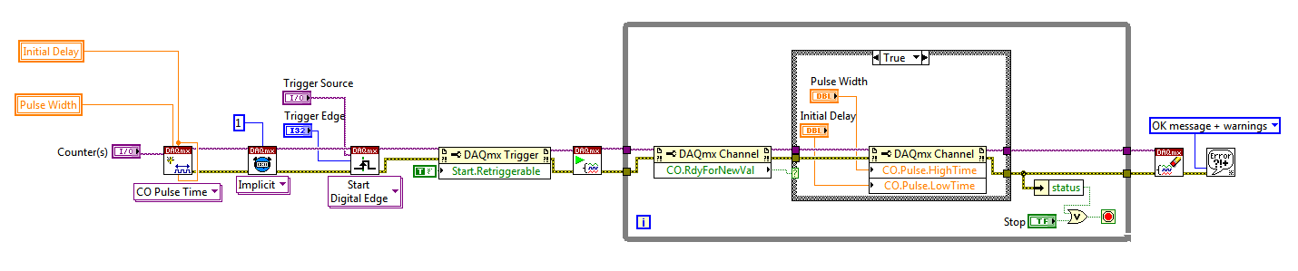
Again, this is not the most intuitive, but I checked that it works on my 6210. After writing a new value in the software the pulse will be updated on the 2nd trigger. Attached is the code stored in LV8.2.
Best regards
Tags: NI Hardware
Similar Questions
-
LabVIEW 2014, report generation tool, excel 2016 and compatibility office 365
Before I try to convince our people IT to improve our desktop software I need to know I'm not going to bite me in the process. LV2014 will work with the latest versions of the individual products?
There is an article OR here that describes which versions of Office are supported by LabVIEW versions: http://digital.ni.com/public.nsf/allkb/C9408B9F08D711E786256F3300701D01
-
The trio of Labview, card PT and Basler A - 610 camera F gray
Hi all
I'm doing a project on the merger of the camera with a PH d teacher. As I am the research assistant I can make all preliminary ups. in any case its very annoying that I'm stuck on the first step. Which is simply the video detection from one camera on LabVIEW. The equipment I use is an A-610f "basler" firewire camera, a gray PT 1394b PCI Express Card (http://www.ptgrey.com/products/firepro/index.asp).
The basler connects with gray map of PT via a firewire cable. Now that the card is not an OR product it is not shown in the MAX I just need to get the video of LabVIEW, but I don't know where I have to access the camera from.
I'm using LabVIEW 8.2.1 and I Vision Assistant and Toolkit Vision and Motion installed on my machine. In addition I just download demo version of the Vision Development module as well. Again for the clarification that I just need to acquire video from my camera.
Finally ive it resolved myself!...
 .. The main problem was with the son of the late himself! .. I was amazed when gray pt was charging me $75 for a firewire cable because it was available in my country of origin for Rs 250 to the free market. I bought one and then started five days of immense struggle and re struggle. Finally, I thought that ive tried all means why not give it a last try and buy the original cable. I borrowed it from a firm surface and 'khatttaaaaaaak'... it works! Although I had to install the SDK of basler to view the video stream. Once the entrance to the camera was visible on the SDK. It was smooth then leave. IMAQ Max was able to detect the camera. The right software was all that remained to be installed. Once the right software has been installed using MAX. It was all great. The power of the camera was visible on max as well. I opened the Vision Assistant and he began to take the camera feed as well.
I decided to transfer to another device in the PCI card and hooked to another quality firewire cable. The repeatition of above process ensures that the camera is fed was visible on SDK, MAX and Vision Assistant. Although permitted high-speed bandwidth continues to be a problem. Another problem which forced me to bite the nail outlet there is over and done.
Moral of the story: use the original substance

-
Beginner: How to set the label of the digital control programmatically?
I have a digital control and I want to put the labels (and unit) programmatically. I've created a property for the text of the label node, and then it changed to a knot of Scripture. For now I have just son a constant in this property. When running I get the error "input unit is not compatible with the current unit." However, the property and the constant are strings "roses." Is what I'm trying to do possible? My apologies in advance for a noob question.
You will not be able to change the value of the property label programmatically. Here is an article in the knowledge base that explains this and a way around:
Programmatically change the label for a control or the indicator in LabVIEW
-
MyDAQ - generation of a digital signal and display on an analog waveform graph
Hello
I use the MyDAQ OR generate a digital waveform with a Frequency adjustable. This is implemented in a program, I already wrote it, which generates a TTL 'like' impulse out of the sound card. I display the result on a graph of analog wave form, and I would like to be able to display the digital signals generated by the myDAQ on the same graph. (Not in the same time, one or the other, activated by a button). I've been messing around with tables and conversions, but I can't really do with all this.
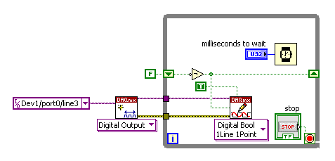
It's the vi, I did to generate the digital signal of frequency with MyDAQ. Any suggestions on how to do this if the following is false, would be great too, as I just got the MyDAQ a few days ago. I think there must be a better way, but it's the best I could come up with so far.
Hi Jonny,
The General logic, that you use to create a digital pulse train is very good. This VI you wrote should work and create the pulse train based on timing of software (which is fine because you have not DIO clocked by the material on the myDAQ anyway). However, it is generally advised to start the DAQmx task just before your time loop and then disable the task after the while loop when you press stop.
For reference, there are a few examples of good enough LV that I recommend you watch too much for this application. If you try just to create a digital pulse train, the example Gen dig Pulse Train - Continuous.vi is a good example that uses a counter to create a digital pulse of your desired frequency train. It is generally the preferred method to create a pulse train, if you have equipment available to do (the myDAQ there a meter). Otherwise, there are a few examples DIO who write continuously in a digital line / port.
If you are unfamiliar, you can find the examples by clicking Help > examples find... into LV then navigate to hardware input and output > DAQmx > generating digital impulses or the digital generation.
Also, here is some additional information on the myDAQ and its counters:
Hope this helps.
Chris G
-
To a result NULL of Labview TestStand to a type of digital test limit.
Hello:
I am looking for a way to pass a null value as a result in a limit test multiple digital test type. My tests are written in Labview.
The tests now pass a value of '-' 999 to TestStand to signify that this measure has not been made, but this requires additional processing and code in our data analysis tools. Passing a value zero would simplify the tool and reduce the workload.
Thank you
Mike
You can switch NaN instead. At least, I think you can. TestStand supports NaN, but I never spent through Labview adapter, so I'm not 100% sure if it will work. NaN is treated in tests limits labview as follows (hat tip to James Grey here):
(NAN > x) == false
(NAN == x) == false
(NAN< x)="=">
(NAN == NAN) == trueI don't know how it would be dealt with when writing a good database. I guess it depends on the data base and values of what digital special supports. A quick search shows that NAN (not sure if he would lift an error or that) does not support Sybase, MySQL stores NAN as NULL in numeric fields, SQLite stores NAN as a special string code, Access stores in the form of NAN.
So you should always write a step for translate NAN for NULL values, but I think it would be easier to write and maintain than an arbitrary number.
-
Generation of waveforms digital series E to 1 Mhz
I want to now that how we generate digital waveform series E through sampling over or contineous. I tested DAQ assistant produced error on the sampling options mentioned above and only worked with sampling of request?
As we already mentioned, your device does not output digital material support timed. Exactly what means the error message. At the request of the software means timed i/o software. means of nothing greater than about 1 kHz timer and which would have significant jitter.
-
Rotary decoder in real-time and 'pulse shifter '.
Hello world
I'm putting in place a rotating decoder for use as a shifter of pulsation by labview real-time.
Basically, this means I have two input channels (ttl-legumes, ~ high 20us) rotary engine. A channel contains a pulse at each CA (angle cranc) ° up to 12 kHz (increment). The other channel contains a pulse every 720 ° CA (the charge cycle, BDC_cc low break-even point). With this information a pulse to be generated on an output also channel ttl (high), which triggers my setup of measurement. This impulse must be moved in a programmable relationship to the entrance of BDC_cc, which aims at a table of regular measure.
I got it running by streaming the channel of BDC_cc until a rising edge is detected, then count the edges of increment to the designated trigger point and then generate a pulse on the output channel. The problem is that the late 70-120us exit trigger. In short it's too; a maximum error of ~ 20 is acceptable. Digital channels appear to work faster, so I put discarded Counter-based acquisition.
I'm quite new to LabView, so I'm sorry if the answer is obvious...
My purchase setup consists of:
PCI-MIO-16-1
BNC-2120
LabView 12.0
Max 5.3.1f0Widows XP
This configuration seems to exclude some options Labview offer, such as the external digital acquisition sampled or externally triggered by the acquisition in the base. A manual interpretation of analog inputs is way to slow.
I have attached my working version.
Any input appreciated woud...
John,
I only have a minute right now, but think I can play with a device simulated tonight or tomorrow.
I'm quite sure that there would be a clean solution clocked by material if you use a series M or X-series
Council MIO, but the older generation counters timers on the set of the E series do support everything which
You need. It's been a while since I had to rely on this generation of hardware.
I think the basic approach is to use the lunatics of angle as the clock pulse train that defines the
delay time of the pulse you want to generate. You could be "Timer" the pulse based on the real
angular position, helping you synchronize to a specific angle of crank. The question is whether and how E-series
counters of takes to support the generation of pulses triggered (or redeclenchables). If they are not, I would say that you consider
get new hardware DAQ which support this kind of trigger and you give a very precise pulse
implementation.
-Kevin P
-
Hi evryone,
Im a beginner with Labview you know I can see a picture in my executable file. In normal VI I see, but when I debug him is lost. Ive tried to find some information on this problem but I've found nothing. Can you help me to smb. ?
THX tom
Dennis is right, you should use the 'path of this screw' primitive and change the path in regards to your insurance VI works no matter where the application runs.
-
Order of the blocks in LabVIEW
Hi all
I am a beginner in LabVIEW. I what is the order of execution of code in block diagram in LabVIEW. It is left to right or from right to left? or y at - it a preference for order as a priority higher than for loops or something like that?
Be a c programmer I think this way. Is it good to compare and understand Labview as well or is it a completely different architecture? Please correct my way to understand things if I'm going in the wrong direction as a beginner. I enclose an example of block diagram, perhaps you can explain with her
LabVIEW does not from left to right, up and down, forward/reverse or any other physical form on the block diagram. LabVIEW is a DATA flow programming language, and it is the movement of data that determines the order of execution. There is a section using LabVIEW called 'data flow programming model' that you should read. In the picture you posted, you will notice screw connected with their error in / mistake the son. These connections are often used to enforce the order of execution. Also, because of its Western heritage, entries are typically placed on the left side of a VI and exits on the left, then you will generally see VI placed from left to right but it's just for readability. If there is no data connection screws separated on the block diagram, they will be run in parallel.
-
NEITHER USB 6008 AI acquisition and generation of pulse
Dear users of LabVIEW,
Greetings for everyone. I am a beginner of LabVIEW and I have a problem that I solved partially. I would really appreciate your help and suggestions that I searched for days without a bit of luck. The problem is as follows:
I am the acquisition of tension HAVE (continue) 4 to 8 accelerometers. In the meantime, I send you a digital output signal each time when you click on the sampling frequency (i.e. 1000, 2000, 3000,...) If the sampling rate is 1000). In other words, try to send a signal of output digital (at a frequency n Hz) at intervals of 1 second (depending on the material). To make the digital output signal begins to blink a LED every one second. In addition, I need to write signals (voltage) AI and the LED blink timestamps PC (software) separately. All stages of the above are followed in my .vi program, but the real hardware/software level operations kill my timestamps. In other words each LED flash timestamps are not accurate, when I use LabVIEW measurement file express VI (the difference is not at least to the third decimal). In addition, the timestamp is kinda OK when I disable the file LVM write VI. Onemore thing I've noticed is that physically the LED blinks every second two times, I feel it's because of the shift register and loop delay of a second. Is there a way to control the speed of blinking (i.e. Boolean State must change to every 500ms without delaying the inside while loop).
Results and comments:
LabVIEW 2011 .vi, timestamp of files with or without generator of LVM (express VI) files are all attached. Please note that there is a considerable amount of drift in the consecutive timestamps when the file LVM generator is used, on the other hand there are derivative of 0.001 ms when the file LVM generator does not. The reason for horodateurs PC have is about aligning the various measures or observations or events to global time scale.
Please give me any suggestions or help me do at least accurate to milliseconds in VI of witten. Finally, is there any USB DAQ module relatively inexpensive which allows to send an impulse to directly from channel impulse of output digital channels when the "n" sampling frequency Hz is obtained by level of material which could all be accurate, so that the software timer is completely reduced to a minimum. Although there are very material sophistiated of NOR, but our goal of this project is to build and test the system profitable.
Thank you and I really appreciate your time and effort inavluable. Have a great weekend!
Just change the samples to the constant playback at the entrance of the DAQmx Read.vi from 1000 to 500.
Lynn
-
Data acquisition in LabView for other suppliers DAQ cards that NEITHER
Hello
I am a beginner in LabView programming. I have a 32 channels base PCI card DAQ (i.e. PCI-1602 of the manufacturer, ICPDAS) and I want it to interface with Labview 8.5.
So how cards DAQ in Labview 8.5, which are manufactured by other suppliers that NEITHER? Should I DAQmx (or some other driver) for that?
What are the other drivers/components required to access of data PCI-1602 (device) of LabView 8.5 acquisition card?
(1602-PCI card driver are installed in my win XP and dispalyed in Device Manager).
Please provide some tutorial above mentioned the problem to interface.
Please guide me in this regard. Thank you
Waqar123 wrote:
Hello
I am a beginner in LabView programming. I have a 32 channels base PCI card DAQ (i.e. PCI-1602 of the manufacturer, ICPDAS) and I want it to interface with Labview 8.5.
So how cards DAQ in Labview 8.5, which are manufactured by other suppliers that NEITHER? Should I DAQmx (or some other driver) for that? You will need the drivers from the manufacturer, of the Board of Directors. In your case, "ICPDAS.
What are the other drivers/components required to access of data PCI-1602 (device) of LabView 8.5 acquisition card? Same as above.
(1602-PCI card driver are installed in my win XP and dispalyed in Device Manager). Ok. Then take you care of my 2 answers above.

Please provide some tutorial above mentioned the problem to interface. To learn more about LabVIEW, I suggest that you try to watch some of these tutorials.
Please guide me in this regard. Thank you
According to what you do with the DAQ cards, they can do the job however, from experience, there are some functions that I could achieve with the cards NOR that I couldn't with 3rd-party maufacturers. This does not mean that this is your case. However, it is worth noting that it took me a while to understand why the code has worked with a single data acquisition card (NOR) but not another (Non-OR).
The drivers that you have installed may or may not include examples and code in VI. They may be DLL. If this is the case, you can write LabVIEW "Wrappers" around these functions, as it will simplify your life. If the drivers are in the form of DLLs, and there are no examples of LabvIEW or available VI, you must read on node library function call.
R
-
How do I turn on/off outputs multiples with a single button using USB-6501 & Labview 2010
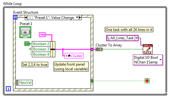
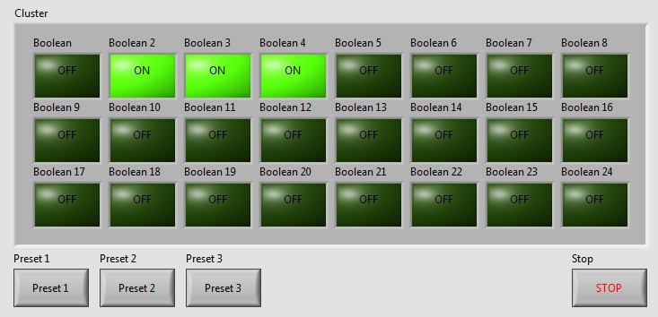
I've written a VI with 24 buttons, one for each output of the USB-6501, for turning on and off 24 relay. Now, I want to add more buttons that activate and deactivate the outputs multiple. We will call these Presets buttons and pressing the Preset button a few outings turn and some turn off. Get it? The VI I've included a screen shot is used to test a transmission controller and rather than to manually select one at a time relay I want a preset button that sets up instantly relays for the next stage of the event.
The VI I wrote uses tasks created in NI MAX.
I am a beginner of Labview, so please try to keep your easy to understand solutions if possible.
Thank you
Kevin
BTW, I'm registered in Core 1 and 2 month next to Richardson, Texas.
Here's an example - you will learn about the grapes, berries, events, etc., in the class, but this will give you a head start. Code is attached but I took a screenshot to give people an idea of how simple the schema becomes:
As your learn about them, I suggest you also make the cluster a TypeDef and make management mistakes, but I've omitted the example to keep things as simple as I could.
Good luck, LabVIEW learning, it is worth!
~ Simon
-
Creating application for archiving of data from the mobile device in LabVIEW.
Hi guys I need help for my application. I need to connect my phone with the PC via USB and then open Explorer with files and folders, that are in the phone, mark and saved and choose the obligations imposed. Something like in this video just in LabVIEW.
Can you help me? I am a beginner in LabVIEW, so please consider.
Thank you.
-
How to simulate cRIO in labVIEW?
Hello everyone!
I m new to labVIEW and I want to simulate cRIO on it. I read all the posts on this issue, but none of them has really solved the problem. In fact, I read the solution given on or developer area titled "how to simulate FPGA targets in labVIEW with the help of the Project Explorer'. However, when I tried to follow the instructions given here, I realized that on the opening "Untitled project" - 'New', my system shows that 'new' as an option "Target Folder" and not "targets and devices." Why is it so? I asked for a few of my friends, but unfortunately they are too new to labVIEW. I, therefore, ask you to help me with this problem. Please answer in a simple language, I understand (a beginner with labVIEW)!
Thanks a lot for your help!
Herschelle
Hi Herschelle,
LabVIEW FPGA for LabVIEW 2011 SP1.
Time real LabVIEW LabVIEW 2011 SP1.
These downloads will give you both of the modules for 30 days free evaluation mode. You can then get in touch with your local branch of National Instruments on 01635-523-545 and buy a license of one of our internal sales engineers. Alternatively, you can also buy the software online through the software product pages.
Product page for the FPGA Module.
Product page for the real time Module.
I hope this helps!
Maybe you are looking for
-
I am a proud user of Thunderbird 24.5.0, but filling unread in my Inbox has no effect. When I click on 'Star' for example, it puts in light blue and shows first tracked messages. Is this a known issue for the OSX of Thunderbird version.
-
AirPrint is not working since 9.3.1 what airprint update - not found. tried the suggestion of JimHdk, who worked for a single document. any suggestions
-
Satellite A-C55-1N1 - how to fix Windows 8.1 after trying Linux?
Hello Laptop: Satellite C55-A-1N1 In my infinite wisdom, I tried to install Linux in dual boot as my old laptop scenario. I have narrowed the main partition of windows in windows 8.1 first and then installed linux on this partition. After the reboot,
-
WiFi starts to turn on and off
Every 15 minutes, my wireless starts to turn on and off repeatedly at a fast rate. I mean, it turns off and then over time offshore on a second and repeat this until I put the computer to sleep, then wake it back up. It of really annoying and makes t
-
Guard updated KB954430 installation
I continue to install the update, updated security update for XML Core Services 4.0 Service Pack 2 for x 64-based systems (KB954430). I have Windows Vista Home Premium with Service Pack 1 and all other updates. I do not have SP2 because I had issues