Multichannel relaxing break
Hello world
I am a beginner with LabView. I'm able to acquire several analog signal of my PCI 6221 using DAQ Assistant, but my requirement is to measure only all my entries with relaxing break for example I need to acquire data only when my example PFI10 is Hawaii. Whenever the PFI10 is Lo, the break of the measure.
I found an example to reach the break here. However, it is only for 1 channel unfortunately. I do not understand about the flow, but I tried several times to add another channel to my purchase, but without success. Maybe my knowledge is limited and only able to start the project of the DAQ Assistant, but not this type of project.
I tried to add another channel to DAQmx create Virtual Channel.vi but he couldn't accept two inputs. Maybe I need some kind of multiplexer?
If the question above can be done, how do I add another measure DAQx Read.vi inside the while loop?
Can someone tell me how to add channels (I need at least another 2 analog channels) on this vi? I think, any other user who are in the early phase like me will all benefit your respons.
Sincere greetings,
Hague
Hello
Found the solution (vi attached). But it is only from 2 channels.
Kind regards
Hague
Tags: NI Hardware
Similar Questions
-
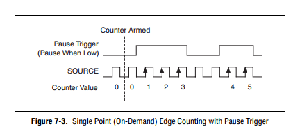
How to generate a single Point (On-Demand) edge counting with relaxing break
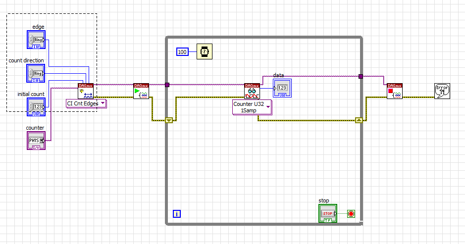
I have problem when creating a Labview program to generate a single Point (On-Demand) edge counting with relaxing break illustrated in FIGURE 1 below. I only know how to build counter edge without relaxing break and my program is illustrated in FIG. 2 and gaskets also. Should what changes I make on my program? The DAQ card that I use is 6259 PCI/USB.
FIG1. Single edge counting with break Point (on request)
Fig.2 my program to generate the edge without relaxing break
It is resolved
-
DAQmx: With relaxing break pulse blocking
I have a NI 9401 module in a chassis 9171 and stand at the door of the output of a counter with the release of another counter. 1 meter (the signal to be blocked) generates a 3 Mhz signal and meter from 0 (the door) generates a 10 Hz signal that is sent outside to door pin of 1 meter. I expect this would be counter 1 door signal to produce the 3 Mhz flashes only when the counter 0 is high, but the wiring had no effect on the output of the 1 meter, it has always generated a continuous pulse train of 3 Mhz. I found that a code is necessary to get a counter to pay attention to the signal to his door pin (this message was particularly useful) and it can be done with the node property relaxing break. After you have configured the node, however, I fell into this error:
Error-20124 occurred at DAQmx start Task.vi:2
Lines 4 to 7 of this port are configured for the entry. Cannot configure these lines for output at this time.I'm quite puzzled by the present. The problem seems to come try it designate 5 PFI ('CTR 1 door' on the 9401) as the source of relaxing break. If anything, I think the error would be that lines 4-7 are configured for output, since these lines are grouped under CTR 1, which is configured as a channel of CO to generate the 3 Mhz pulse train, and the definition of line 5 as the break source changes the configuration on an entry. Looking for this error in the forums OR and Google isn't pulling up of troubleshooting information. I tried to create a task to configure line 5 as a separate digital input channel, but then I get the error saying (error-200125) opposite that lines 4-7 are configured for output and cannot be configured at the entrance, to make things more confusing.
Any thoughts would be appreciated. I'm afraid I'm missing something obvious about blocking the impulses or CO channel configuration as I continue to read that one of the benefits of DAQmx on Legacy DAQ, is that it makes easier routing signal. I'm using LabVIEW 2012 (32 bit) with DAQmx 9.5.5 installed.
Hi agoncalves,
I took a glance at your VI and I see two immediate problems:
1. it is not guaranteed that the two tasks will be reserve before the start of each one. This explains your error and why it seems confusing. The 9401 is configurable nibble, but you cannot change the direction while the device is being used (why the reserves are important). The module starts with two nibbles the input value. Your first task causes an exit so it switches direction on one of them. When your task is committed (started), it hangs in this configuration. The second task then also try an output drive, but on the other nibble that is entered and can not be activated because the first task is currently running. The solution is to use the thread of the error to force the order of execution (or use a flat sequence structure).
2. you won't run out of problems with your trigger signal unless that connected you to a separate entrance (and put the two trains of pulses on the nibble even). You can change that by setting the property of canal CO. Pulse.Term. that's if you want to spend your signal through a few circuits external and back in. If you use the signal directly, you can just use it internally. By example/cDAQ1Mod1/ctr0InternalOutput
-
DAQmx how to control the level of tension AO paused for a relaxing break?
I have an application where I need to generate a waveform of a fixed frequency (~ 200 kHz) and the amplitude, but for differing them burst lengths and different lengths of time between bursts. These bursts and these delays are controlled by a line of DIO to generate the relaxing break. I also need to have the output voltage analog voltage controlled between bursts of waveform. I explored using various trigger options, the break seems to be the best solution, but I'm difficult to control the particular point of the end of the waveform during the break occurs to make sure that the break is at the same specific voltage when the wave is hidden. I try to adjust the position of the example 'Analog output Pause for the periodic Signal with regeneration on specimen' but cannot get regular tension during the break I'm after. I use a card Series DAQ. X is there a simple way to pre-set the tension that will be broadcast during the paused state when using a relaxing break? I was not able to find it in the examples or documents. I can't use the code of reference AO set example because it is a software-driven and does not fit into the model of schedule I need to generate.
Hello
I don't think there is a way to establish a certain level on the analog output, based on a relaxing break. I watch using a redeclenchables task analog output and do every hour of beginning to the required voltage.
-
How to build a single Point (On-Demand) edge counting with relaxing break
Hi, I am building a clock as shown below. It is also called 'Single Point (On-Demand) Edge Counting with relaxing break'.
"
I have problem to find the code example. So far, I can only build a counter edge without a controller trigger like below. Could someone help me?
-
Question about relaxing break: multiple triggersources
Hello
I have two digital signals I want to use as the source for the start of the break. The outbreak of the break is done with a triggernode. The problem I have is that I can add two sources to the node, but it will not react on both, only one. So I guess it only accepts one signal. The first triggersignal will start recording for an unknown duration. When the first triggersignal falls, the second trigger signal will follow immediately and continues for 5 seconds. Perhaps there is no need to add a second source of relaxation as the time that the signal must be connected is known and follows directly after the first trigger signal. But I can't seem to find a solution for this.
Another problem I have is that I connect to a frequency of 100 Hz but on my excel file, I find that 500 samples after 10 seconds of recording. IM connecting signals 2 NI9237 and a NI9219. The NI9237 rate is 2000 Hz but I it decimate to 100 samples per second. The NI9219 signals are recorded at 100 Hz and are intact.
Thank you
Found my other problem also. I was break trigger with a virtual channel that was constantly on and outside facil (unknowingly). Up to half the time EMS was not be connected. On the front panel, the check light was still green, but I guess he can't follow the signal so fast.
-
Button - ranging from relaxing break time
Captivate 8.0.1.242 - Windows 7 64 bit - format swf
I add a button that runs a term action advanced exactly like this post (CP8 - add a replay on a slide button for). I have a 1 minute video CPVC. Now, I want this to exist always replay button, but not pause the slide. I have other buttons on the slide that takes care of pause before dragging the output. But this BACK button comes with a break. Anyway, like any other button, I'm trying to move the break in the timeline using the mouse slip and fall at the end of the timeline around 59 seconds. But whenever I drag beyond the current view threshold line time including 17 seconds when captivate is maxed out, the break dates back to about 3 or 4 seconds in the timeline panel. It's so weird. I don't even need this break and if I try at least to go beyond the length of the video, I am facing this problem.

CP8 stupid Newbie UI! The suspension and the duration are more in the properties panel, but in this Panel of timing:

I never use the Newbie UI where everything is controlled by CP (I don't like be). Maybe you will see it in the docking station right when you select the button? Or he must go to the window menu, and then select properties for synchronization?
-
Logic multiply instead of relaxing break
Hi all!
Can someone help me with the meter by another,
I want to produce modulated timebase, otherwise first generate impulses in continuous mode, and another did the same thing, but with a lower frequency.
for example = 20 Hz f1, f2 = 0.1 Hz. The first counter blocked by another, there is no option to stop temporary counter1 where counter2output is in a low state of logic, I want to produce OUT timebase = [ctr1out] [logic multiply] [ctr2out], do not pause.
---
Alexander.
Hi AlexanderRyabov,
If you want to produce a modulated time base, you should be able to do this by connecting the outputs of the 1 meter and 2 meter at the source and the door of a third meter. The low frequency counter would be connected to the door and would act as the signal to toggle meter of high frequency that is connected to the source. The result would be when the impulse of low frequency counter is high, the output of the counter 3 will expose the pulses of the meter high frequency counter 1 and when the pulse of low frequency counter is low, the output of the counter 3 is low for the duration of the door (counter 2) low pulse. This is equivalent to a logical multiplication of signals two against.
Here is a link on how to deliver the outputs of the two counters at the door and the source of a third meter on the map you are using:
http://zone.NI.com/DevZone/CDA/EPD/p/ID/2109
I hope this information helps!
Kind regards
-
How to stop the acquisition with a relaxation with the NI PCIe-6323
Hi all
I wonder if it is possible to stop data acquisition or pcie-6323 with a trigger pulse the same way that I begin to acquire samples with a finished sample mode trigger pulse.
Thanks in advance
M.
The samplesPerChannel that you can show what the sample clock configuration defines the total number of samples for the acquisition of finishes. In your case, you will read the data previously triggered so permanently in force this setting really only sets the size of the buffer. If you want to just be large enough to avoid overtaking (although...) If the window you buy is potentially very short, you might want to explicitly configure the size of the buffer to something bigger and maintain the value of samplesPerChannel down so that the reference trigger can be accepted earlier).
The numberOfSamples you specify when you start the player defines the number of samples for the next call for reading. If you can read the small windows of streaming data to avoid having a blocking with a large timeout call. If you do not want to change the time-out period, it is a property of the DAQStream class.
The "continuous" examples (e.g. this one) should show how you can read back data asynchronous as it is acquired. Your configuration looks more like a "continuous" example
Since you want to start and stop using the same line as the trigger, perhaps an alternative to the evolution of the default read pointer would be to set up a central task of analog input with a relaxing break. The caveat to this is that the break does not stop at the task and as soon as the line goes back to you will begin to acquire the data again - I would say using a meter to separate groups of samples in the buffer zone continued. If you wish to purchase multiple windows of data in short succession well, then I would go with that instead to avoid having to restart the task (and potentially Miss samples during the restart of the task).
Best regards
-
gated two error of counter-200452 edge
Hello Forum,
As I wrote earlier, I am implementing a measure of separation of two edges that can be blocked. In an updated version of an earlier program, I tried to use the node property relaxing break. However, I can't work and still receive a 200452 error. Can someone at least explain what the problem is (attached) program.
Kind regards
RL
Hello
See this.
Kind regards
Lily
-
I use a 6363. I want to trigger a pulse to synchronize incoming exactly N times. These impulses are coming in the ~ tens of kHz range.
My first idea was to make a task of CO County ticks on the same impulses and plug a relaxing break, but pause triggers apply only to the continuous acquisition.
My next idea was to hang the task of CO County ticks as the arm trigger defined on 'Good to go if it is high' and not 'arm on front amount', but it seems that it is not in the cards more.
Another idea was to use the impulses of synchronization entering as a sample of clock on a binary ripple of 10101010101 (N repetitions) and use the trigger set instead. But it seems that the binary signals cannot be deployed to advance until its next value on a rising or a falling edge, therefore leading to another each pulse.
Do I need to use a transistor outside Commission to do (with County CO ticks)? Who would do it, certainly, but it seems kludgy.
.... Are there clever ways to do? If not, is there a way to get the binary waveform to advance on the edges of increase or decrease?
It has a hardware signal as well (that confusingly enough is called the "change detection event"). "You can use it by setting your clock source' /
/ChangeDetectionEvent '. It will not be displayed in the drop down menu to DAQmx default termnals because it is considered 'Advanced' (see here). Best regards
-
Using a counter with FiniteSamps and one with ContSamps
I am using 2 counters on the NI USB-6229 (or USB-6259), case where a counter is implemented for FiniteSamps and another for ContSamps. I have the following MeasurementStudio code:
ErrChk DAQmxCreateCOPulseChanTicks(hCnt0, "Dev1/ctr0", "", "20MHzTimebase", DAQmx_Val_Low, 0, 400, 400);
ErrChk DAQmxCfgImplicitTiming(hCnt0, DAQmx_Val_FiniteSamps, 100);ErrChk DAQmxStartTask (hCnt0);
ErrChk DAQmxCreateCOPulseChanTicks(hCnt1, "Dev1/ctr1", "", "20MHzTimebase", DAQmx_Val_Low, 0, 400, 400);
ErrChk DAQmxCfgImplicitTiming(hCnt1, DAQmx_Val_ContSamps, 2);
ErrChk DAQmxStartTask (hCnt1);
When I run it, I get an error-50103 "the resource specified is reserved". If I change the FiniteSamps to ContSamps on the first counter, everything works fine.
If I use only one counter with FiniteSamps, everything works very well.
Is this a bug in DAQmx or the use of double counter on M Series devices is limited to ContSamps?
VIC
Hey Vic,
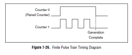
It is actually planned on a device of the M series. Here's a time diagram of the M Series user manual which might make this a little clearer:
The device uses actually one counter for the other door so the result is a generation of finite pulse. If you can provide the door from another source, you can configure a generation of continuous pulses on two counters and their door (DAQmx calls it a "relaxing break") of this external signal.
You can also look at the use of the digital I/o correlated to generate impulses over multiple (up to 32 lines on your 6229 and 6259). You could use one of the counters to generate a time base for digital lines and build the waveform as a result.
One thing to note is that our new X series cards can generate a generation of impulses finished on a "single" counter (it was actually a paired internal counter that allows this). There are four accessible counters by the user on the X series devices, which means you could generate four pulse trains finished.
Best regards
John
-
Continued use of digital dashboard to stop a generation pulse train
Hello
I need to generate a train of pulses for a period of time. However, this period is variable, and because of that I can't
Use the finite number of samples.
The pulse train must be output depending on the State of the digital I/o. When the line output goes high, must be output of the pulse train.
and when he goes down the pulse train should be stopped.
I use a USB-6212, but is already using one of the available counters for the measurement of pulse width. I tried to do a
AND logic with the pulse train and line activate, but due to the execution time of vi this solution modifies the pulse train
frequency, which is not acceptable.
Thanks in advance,
Mariana.
Hi Marianne,.
Your previous message mentioned "line in/out" (in the singular) and "enable line" (in the singular), isn't "the i/o lines" (in the plural). Are the two edges on the same line in/out? Or are they on separate i/o lines (for example, climbing on PFI0, falling on PFI1)? Can you clarify your needs?
If the fronts and sides come from the same line of output, then a relaxing break seems to do what you want: cause the meter generate impulses while the input/output line is high and cause the meter to stop while the input/output line is low. However, if you start the job, while the input/output line is high, it will immediately start out impulses. If you want to wait the first front line input/output to generate impulses, you can use a trigger 'start of arms' (which is just below "break" in the node property). When the trigger 'arms beginning' arrives, the meter will be armed, and therefore, the task uses the break to determine when to generate impulses. Using pause and start the same counter task returns error-200146, "put in Pause and start triggers cannot be active in this task," but using break and triggers 'arms beginning' in the same task of counter should be correct.
If you want to increase the edges of PFI0 to start the meter and the fall of the edges of PFI1 to stop the meter, which is more complicated and it will take thought additional (and possibly additional hardware).
Brad
-
ContGenVoltageWfm_ExtClk-USB-6001
Hi all
I just got USB-6001 and tried to go although the demo examples. The question is about the "ContGenVoltageWfm_ExtClk". To after my understanding, there should be no signal AO while no pulse train provided the sample clock source defined (/ PFI0). However, AO signal is always generated as if it is running an internal integrated clock. I use Examples\DotNET4.5.1. Support for USB-6001 external clock example? Any help will be appreciated. Thank you.
Hello
The Specification 6001 OR don't mention external trigger. To compare with another product, here's the Specifications NI USB-6211. On page 9, there is an external digital triggersection. for the analog output function, PFI can be used as Trigger Start, relaxing break, sample clock or time Base clock sample.
This let me think that the external clock for analog output is not supported by NI 6001. Check if for example there are a list of supported hardware.
Best regards
-
Support for triggers in PCI-6602 for counter input / output meter opearions
I'm sorry, it took a lot of time to test my application in a real NI PCI-6602 map. I am now convinced that put off against channels support start trigger, arms and relaxing break start trigger. But the input meter channels use pause trigger and trigger start of arms only.
I designed the app so that counter 0 is used as a channel of the meter and meter 1 serves as an output of the meter channel. The two channels are configured to use triggers to start of arms. Arms start triggers should come from a line of the RTSI. Using the terminal line 0 RTSI route connect API to arm the trigger for the start of the two channels. So when a pulse comes to line 0 in the RTSI two counter starts counting.
One last thing, I'd like to know, is how RTSI signals are generated? I know that RTSI is used for synchronization of several cards of NOR.
If there is only Board can we use the signal of the RTSI?
Can the hardware PCI 6602 itself generates all signals to the RTSI lines?
Thanks in advance.
Johnson


Maybe you are looking for
-
[SPAM] tag on known addresses.
I use thunderbird, latest version, for windows Vista.I get the [SPAM] tag on known email messages, and they just stay in my Inbox. As [SPAM] topic: I don't know why she is doing this. I use avg, which analyzes the e-mail, but I only installed a few w
-
Firefox worked fine with AOL mail for years. It is now useless. Sometimes he even not open AOL mail and when it's the 'response' and 'forward' does not work. Now I have to go to IE to use AOL mail
-
To access the files with the appropriate authorization
Hello everyone. I tried to fix something that I screwed up a long time ago. Here's how it started. I have this drive external DRIVE that I keep my photo archive to. I was going to somewhere that I don't remember now, so I wanted to keep away from cur
-
How to use Labview "" buttons"" in the operation of the program?
I try to use the ok button to run the program adds to the value of the cluster X Y (millemetre) [which is the operation of machine vision] with value X Y offset [which i will to enter myself] but... I don't ' know how it does do, now I try to use the
-
How to re - install SolutionCenter.msi for Windows Vista
How to re - install SolutionCenter.msi to my Windows Vista?