Multiple VISA written communication SLOW Arduino
Hi all
First of all, about this project: this is my main project (EET) and I worked on it for about 2.5 months trying to go forward for my last semester this fall. The concept is to perform a coil using LABVIEW as an interface A) has user input that is sent to an Arduino MEGA 2560, B) puts in place a Tektronix O'scope and sends a current reading to Arduino (Arduino is also exciting coil) while drawing the curve on the LABVIEW UI as well. I also have the relay of Arduino, monitoring of battery voltage control, impulse control, etc.
This original program works and it does everything I want it, even if I have to wait before 1100ms each entry VISAS for Arduino properly receive the variables. Do this many delays makes the program take about 10 seconds to finish and I needed ~ 5 for a full run.
Last week I did experiments, initially I had each sequence of entry VISA in his own stacked, but now, I tried to put every entry VISA in his own while all in the same stacked sequence with the lines of resources VISA controlling the sequence. Basically it does the same thing and works with 1100ms in the loop with VISA Write or if I highlight the execution without delay. I can't find anything on consecutive multiple entries of the VISA on the web that is close to what I do. If anyone can give me direction, I would appreciate it.
Note: These newer programs I write are about half of the total program because they are the parts that I have problems with.
Thanks in advance!
OK... crossrulz I think you put me on the track after a week of messing around with it. haha
Seems what arduino has a default series which is like a second, then my arrears had to be a little longer than this timeout, I guess. I put the time-out to 250ms for this part and with a delay of 150ms before an entry VISA paired with little crossrulz termination character, it seems to work pretty well. I hope this helps someone!
Final solution to this below.
Tags: NI Software
Similar Questions
-
VISA reading significantly slows down to 20 Hz (Labview, Arduino + Xbee project)
Hello
I am quite new to Labview and Arduino, so I apologize if I use the incorrect terms. I'm having some trouble with the next project, I hope that you guys can give me some advice!
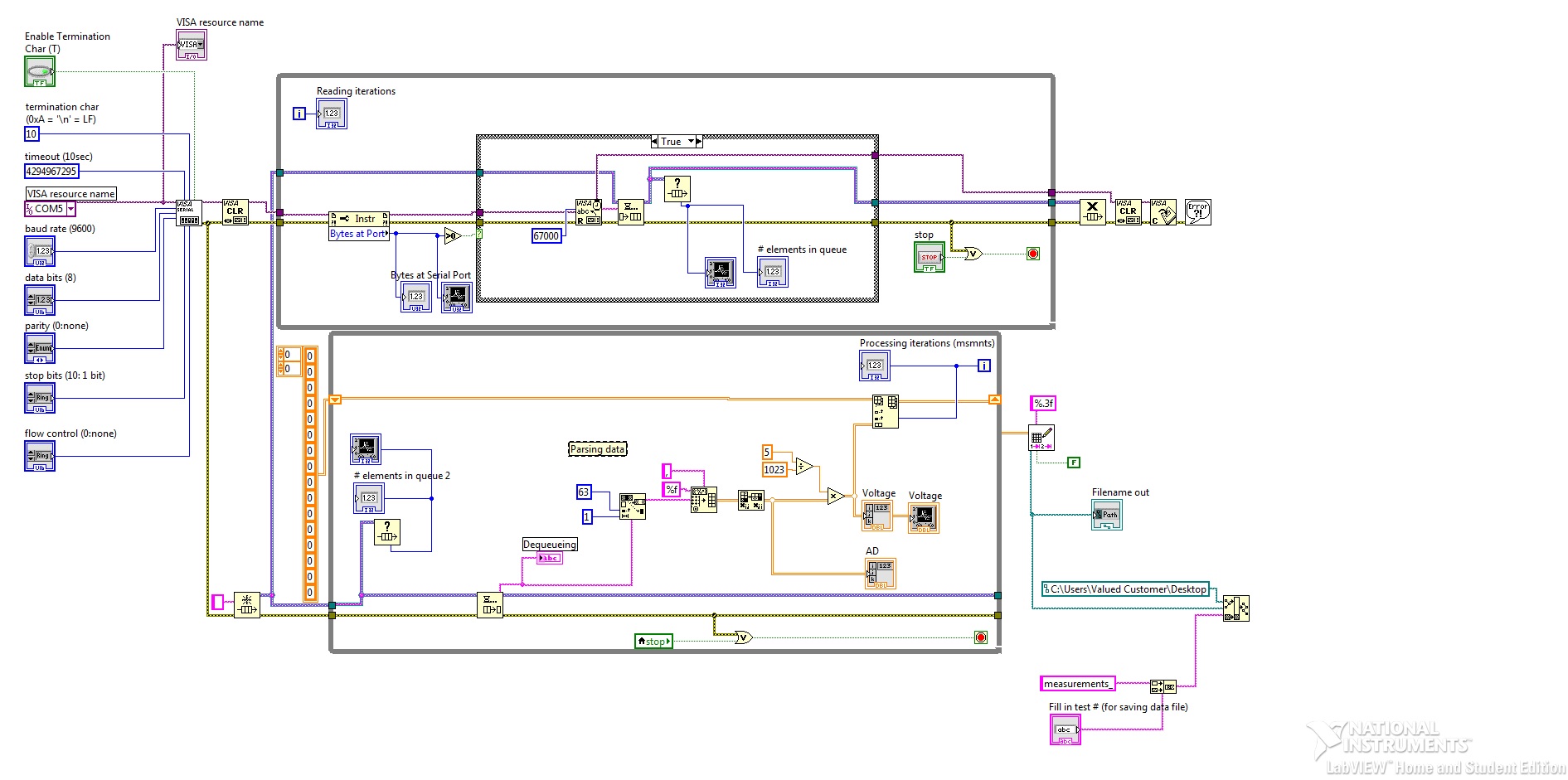
I have 16 sensors connected to the 16 analog pins on an Arduino mega Board. This Council has a shield mounted upon him, with a Xbee module wireless. I have another Xbee module that communicates with him and it is mounted on a USB dongle that plugs into a PC with Labview 2015.The A/D analog Arduino pin output is read and sent every 50ms to the Xbee module connected to the PC. So every 50ms (that is, a frequency of 20 Hz), a new line of analog readings by commas is sent, using AnalogRead and Serialprint in the Arduino. These data are fed to a Labview code with architecture of producer-consumer. Copy the following code configures a serial port of VISA, reads the data, it converts a voltage value and writes the data to a text file (see block_diagram.jpg).
The problem is that at a frequency of 20 Hz (with the configuration of the attached jpg) when you reach 400 treatment iterations the code slows down considerably and values are not parsed correctly. It behaves as if the queue is full (but the queue of elements indicators show 0) or memory or the buffers were full. It seems quite surprising to me given that the sampling rate is so slow. I tried a few configurations setting the buffer size, empty the buffer by using the queue time, but nothing seemed to work. Is it because the processor loop takes too much time to iterate? I tried to disable data analysis, conversion of voltage and the generation of text file, just keep reading and still have the same behavior.
This may be the cause? Suggestions to change the block diagram are welcome! Is there a better way to do this than with VISA or queues...?
I use Labview 2015 on Windows 7.
Thank you!!
sminanog wrote:
It behaves as if the queue is full (but the queue of elements indicators show 0) or memory or the buffers were full.
You think along the good things. But the big problem I see here is that you have a table growing up to stop the program. You must move the file writing to be inside the loop of your consumption. This will eliminate the need to constantly develop your table in the shift register, with tons of memory and causing copies of memory (which is very expensive).
The other concern I have is the speed at which data is available. If you have a baud rate 9600, then in the 50ms debit you can pass 48 bytes. This leaves 3 bytes per sample, including the comma. If you have a debit 115 200 baud baudrate, it turns into 576 bytes, you can send the 50ms. So the lesson here is to make sure that you use a transmission speed which is fast enough to handle the data that you want to send.
-
VISA read very slow communication
Hello
IM using serial communications VISA in my project and I noticed that the reading block works very slowly.
I have the microcontroller that connected to my laptop through XBee modules.
Baud rate is 9600 due as a change factor in each component in the line won't make a difference at all.
Also, I checked that it work with terminal XCTU and its working fine (very fast). so his can not be something else except read VISA.
Please see VI attached file.Thanks for any help,
If you do not use a stop character, then the read VISA will sit and wait that 100 characters have been received by the COM port or the timeout elapsed (which is probably something like 5-10 seconds long). You can change the time-out period (using a property node) or reduce the number of characters you read each time that the loop runs.
Without a termination character, you will need to build your own string using a shift register buffer - whenever you make a VISA read, add it to the chain on the shift register and then do some analysis to take control of your microcontroller (e.g. alarm, coordinated) and remove all the foregoing orders of the string buffer (for example if you have started the VI in the middle of a command) ", then you don't want to throw these data).
-
Writing of multiple orders with communication series
Hello
I'm quite familiar with the basics of LabVIEW, but I'm new to communication series with VISA. I had no chance of finding a solution to my problem, but it is similar: http://forums.ni.com/t5/LabVIEW/VISA-read-write-to-serial-port-Unable-to-impelement-multiple/td-p/93....
I am able to send a command and read the response with the device, but I can't send several commands to change the settings of the device. For example, I send 'F' to the device to read the current operating frequency and read the response (22). But if I send 'f' to the device to change the operating frequency, read the answer ('send frequency... (''), then send my desired frequency (120), I get no response.
The default frequency at the opening of the port of the unit is 22. I would like to change the frequency to 120, then read the current operating frequency to ensure that it was indeed changed.
I'm confused about the format of data to be sent in LabVIEW. In MatLab, it works fine if I send 'f' as a character (fwrite), followed by the desired integer frequency. However, in LabVIEW, it seems that the number I want to send is not read correctly. I have tried to cast the integer to a string and read that the slash code, hexadecimal, normal code, all I could think about.
Help, please
This give a try. Press the button "Prepare", followed by the 'Set Freq' button. You need to configure your serial port properly first well.
-
Problem with Labview communication with Arduino Uno
Hello
I tried to run a simple program in labview through my Arduino Uno R3 all morning and keep running into the same problem: no response from my Board of Directors. I'll catch you up on what I've done so far:
-flashed LIFA Base to my Arduino
-Downloaded the driver update of VISAwritten-a the block diagram (I hope) for a led on off function
When I run the program in labview, the RX flashing intermittent, continue for 30 seconds before stopping. The led on pin 13 is not turned off as it should, and I have no control over the power function light. I also tried a program of control of servo with no response and the same flash of RX. Never the TX flashes.
I am quite stuck, so any help is greatly appreciated. Also I'm not a comp sci guy, I'm just an engineer in mechanics with a half of C++ so keep pg when it comes to the language of the computer.
I've attached a picture of my diagram of LED, see if you can spot a problem.
Thanks in advance!
SOLVED: Reset the Arduino card after that labview had sent his orders (while the RX light was still flashing). Works like a charm.
-
I2C communication slows down over time using USB-8451
Hi all!
I try to communicate via a device slave using a USB-8451 I2C and I noticed that after a while the communication speed slows way.
I can send and receive data very well and apparently my system seems to work. But the problem is that over time the speed of data transfer slows down so much so that if I let it run all night it has slowed to a crawl in the morning. My ultimate goal is to gather data, draw and save every second and at the beginning it is easily achievable, but after 10-15 hours I can no longer collect data as fast I need. I'm not quite sure if this is a problem with my code LabVIEW, the NI USB-8451 box or the slave device. But if I stop running the LabVIEW program and start it again, everything returns to normal.
The slave device is a personalized card with a microchip PIC which acts as a slave I2C and returns the data at the request of the master. I can't imagine anyone will be able to determine if this is a problem directly, but if we can rule out the other two (code LabVIEW or the NOR-8451) as the source of the problem so I know it's my slave device.
I've greatly simplified the LabVIEW code that I used to collect data on I2C and I see even this gradual slowing down over time. Attached, it's that the very simplified VI and the data file, it produced. I only ran it for about 45 minutes, but from the beginning to the end we see again that the enforcement timeframe is rising.
I hope I'm just doing something stupid, thanks in advance!
-Aaron
Aaron,
Do not have the additional module responsible for these functions, but I'm sure I know whats going on. It seems that each time through the loop 'OR-845 x I2C Create Configuration Reference.vi' creates a new reference. After a while it will start to slow things down. Better to open the reference before the while loop starts and spend just the reference in the loop. Don't forget to close the reference after the loop stops.
-
VISA + Serial Communication - need help!
Hello world
I have a lot of help with my project of this forum and I'm looking for more
. Thank you for taking the time to help. Please bear with my as I ask a LOT of questions.I intend to control a frequency converter using its series terminals and send orders from my PC + LabVIEW it. The commands do the basic functions like, start, stop, speed up/down etc etc. I use a converter Series USB to transfer data.
Now, I ve played with examples like SERIAL COMMUNICATION VI and others and I begin to understand the functioning of VISA.
Q1. In order for LabVIEW + VISA contact my frequency converter, do I need to install some sort of a driver for him to recognize? The frequency controller is old ages, even I don't know and I don't think I can find a driver for it any time soon? What kind of driver I'm looking for? Is it possible to customize my own driver and which would be easy?
accessory included - process.jpg
I downloaded some pictures about the problems of data format. I need to send information to the converter to format "telegram" as shown in the image below. Each 'function' in the 'format telegram' has varied length in bytes: some have 1 others have 2, other 4...
I also downloaded an image called "Format.jpg" which indicates what information each of these 'functions' will contain. Note:-the frequency converter uses only the last 4 bits.
Say for example:
START function will have this bit of information-
Start the Byte - ASCII ' 59 "
Address - 00
Control character -? I'm not sure what it should be I need to use the converter based on parameter values - is confused on what to choose - C, U, I or r Start, stop, etc. have their own specific parameter values such as 402, 404 RESP, so I guess I want update (U)?
Word of State control -? depends on the previous action
Sign - do not necessary
Data - 0
Comma - is not necessary
check the sum - is not necessary
Stop the Byte - ' > ' (ASCII: 62)
Phew... How would I go about clubbing this whole format together to send a control signal? Put all this information in a table allow somehow?
Please help to me... to achieve desperately need...
Thank you
Sandeep
It would be useful that you could find a driver, but it is not absolutely necessary to have a. You can write your own, use the Instrument i/o Assistant, or use VISA readings and some discreet.
The format of the commands is a bit complicated but not impossible. You just need to be careful to have the exact number of bytes.
What I don't see in the atttachments, it is possible words to control and the State and the number of parameter. I hope these are in another part of the manual.
A bytes example (without the control and settings) to update the frequency to 12.34 could be '<00U________+123403??>'.
-
I found whenever I place using several nuclei, the guest is super slow. Does anyone know the reason? The system specification is 2 Core i7, which has 4 cores, each with hyperthreading, i.e. 8 logical processors.
This phenomenon occurs on OpenSolaris and Windows Server 2008 R2.
Specifically, once before that I wrote a program, which is purely CPU bounded, which has no IO and memory very little access, to test the performance of the processor. When I compiled and run it in OpenSolaris guest, running with a thread as quickly as if it was running on the host computer. However, when I use 2 wires, each is significantly slower than the single thread. The guest of OpenSolaris is configured to use 2 CPUs.
The other observation is when I install server on Windows 2008 R2 comments RAID5, it's fast (16-20 MB/s), if I put it on 1 CPU. But when I try to configure 2 CPUs, performance decreases signifantly (3 Mbps), and the guest is so slow that there can be no answer to my mouse click.
My conclusion is therefore, on my machine, it seems a CPU is fast (near-native), but multiple vCPUs a performance problem. Isn't anyone know why or know another thread has what? Thank you very much.
BTW: my host CPU's Core 4 w / HT, but I set up my guest for 2 processors and 1 for each processor core. Change to 1 CPU with 2 hearts on this subject will be better?
icando9 wrote:
It is not quite explain why.
Not necessarily. It is a rule of thumb, not a law. Depending on how many clients and their number of vCPU and on the load on the host computer, this may apply. Even if all clients except for one have only one vCPU this particular comment with still two of vCPU must wait until the two nuclei is free. Who takes always longer than if she is not to wait two hearts.
In general, you should always start with the least possible vCPU. Virtualization environments attributing more vCPU can degrade the overall performance.
In addition, according to the guest OS a huge load of CPU interrupts is generated by the virtual timers. According to the kernel Linux, for example, can generate 1000 + 1000 x n (n is the number of vCPU) interrupts per second per guest.
Two guests with such a core, and each of them with two vCPU to generate a load of 6000 interupts per second, even when they do nothing else.
BTW: assigning 2 processors with 1 core each and 1 CPU with 2 hearts makes a difference?
Yes it can. Depending on the application. If she makes intensive use of the caches of the processor that best you do not want to have two vCPU running on a CPU cores because they can use the same hidden then.
AWo
\[:o]===\[o:]
= You want to have this ad as a ringtone on your mobile phone? =
= Send 'Assignment' to 911 for only $999999,99! =
-
visa usb communication in bulk - several end points
Hi all
I'll put up a spectrometer optics USB2000 + ocean and want to use visa instead of the dll that I had with the spectrometer (I had a lot of stability problems, moreover, this is not supported by the ocean optics and I won't have to pay for the new version). I have documentation for the spectrometer and were able to set the integration time and receive ghosts as quickly that the dll has been able to. But I was not able to read the information of calibration of the spectrometer. All controls use the transfer block, so I use visa read and write to send/receive. I think it's the difference between the spectral data and calibration data, that the data comes from different points of termination. The spectrometer has 4 endpoint addresses (3-PC = IN, 1 PC = OUTSIDE). The spectral data returns to the first endpoint and the calibration data is on 3rd in.
Is there a setting I need to change to read from a different end point? They are all in bulk type according to the documentation. Any suggestion would be appreciated.
Thank you!
Hey gharris,.
It seems that there is a parameter, you can change by a property node that will change reading from what endpoint. If you use a text-based program, the property, you need to change is VI_ATTR_USB_BULK_IN_PIPE. If you are using LabVIEW, follow these steps:
First of all, to ask a VISA property on your block diagram node (really any node property works). Then, right-click on the property node and select Select class-> VISA-> / o Session-> USB Raw. This step can be found in attached below EndpointSS1.png and change the property node to a node property USB Raw. Thirdly, left-click on the property and select settings USB-> pipe in bulk. This step can be found in EndpointSS2.png, attached below. It is the property that defines at what endpoint to read from. To change the value of the present, right-click on the property node and select change all to write, which will allow you to connect to an endpoint value.
-
Visa series parallel read with arduinos, data are delayed
Hello
Currently I use two arduinos asynchronous data read from sensors of temperature and humidity. Each arduino send back 4 floats, separated by commas, with a stop of "\n" character In labview, data gets broken upward and then pushed to live plots. In addition, the data gets written to a file - arduino #1 and #2 Arduino have their data sent to different files. It is important to note that the arduinos have different rates by which they send data on the comms series. Ideally, we would like that the data of every arduino to enter and update locations independent real-time each other.
I'm having a problem where data do not seem to be displayed in real time. I can touch a thermocouple and then ten seconds later, the temperature will change. This delay seems to grow over the short program, which is a problem since we use a direct result of the plots to determine when to start various processes of cooling.
I wonder if due to different data rates the thrust arudiunos, if there is some kind of buffer somewhere that has a "backlog" of the fastest arrduino data and must wait for the slower arduino data until it does nothing. It is obviously a problem of data flow, but I'm pretty green with LabView and was looking for some advice or pointers. I want to mention that the arduinos send data quickly; they send every two seconds or more.
Hello MrScientist,
can you please try to use two separate while loops, one for each COM port, because if they're in the same loop, it can happen that they block each other.
A second option is always read all the information on the COM port and made a ring buffer and filter information of these buffers.
-
Serial communication error VISA with LUDL stage controller
Hello
I'm trying to control a micro-positionnement made by Ludl stage. The model is Ludl MAC2000. It seems that the RS232 comunnication is implemented because I can talk to the controller using HyperTerminal. However, when I want to do the same thing through Labview, I can't answer the controller at all. The vi is roughly the same as the visa basic read/write in the example. Looks like a very similar problem in this post:
But the trick of nature of endpoint does not help in my case: I tried to toggle the termination character setting in the property node and different combinations of '\r', '\n' as termination characters, but nothing has worked so far.
Seems to me there is some difference between the interpretations of the same order to Hyper Terminal in Labview. But I just can't understand what it could be.
Anyone with a similar experience could give me some comments/suggestions? Thank you very much!
Another difference between hyperterminal and labview is the speed of sending characters.
LabVIEW breaks out the whole string to the controller
HyperTerminal is this character by character. So much slower and slow the controller can be affected by this.
You could add a loop around the writing of visa (to make it easy convert the string into a byte array outside of the loop and convert it to a string inside and you have a shipment char by char in LabVIEW
-
Hello everyone,
I am now looking for some time to solve my problem, but I couldn't find anything by working for me. I try for the first time to implement a communication series through the VISA screws to my arduino uno card. I was following the most simple of examples that I could find, but nothing has worked so far. I have attached my minimal example. I thought it should work really that simple...
The thing is:
-Serial with my arduino works in principle. He does what he must do by using the Serial monitor to come with the Arduino IDE
-With the help of my vi, that nothing happens
-The number of return always 0. I thought that it should show the actual size of the buffer. If my conjecture is that the vi is simply not written anything in the buffer.
I know that there are tons of other articles on serial communicationvia visa between labview and ardunio, but I could understand them just how I use the screws should actually work.
Anyone can see my mistake?
OK, nevermind. Of course, just after the announcement, I tried the thing that has helped: you can't have the Arduino IDE and LabView open at the same time. Both try to access the same port COM does not work... As I see it, it's my problem. Sorry for the gene :-)
-
Hello..
I have no problem with reading series. I want to playback multiple visa series... Fist read I want to read the data of 5x8bit uC then if visa data read isnot "NOT" I'm going to send data to the CPU as the character ' end then read data from uC to new but is leght data 2x8bit data...
Please, help me...
This is the number of bytes you want to read. You already said you first want to read 5 bytes. If you use VISA set up the Serial Port and the stop character allow to true, you can set a number of high bytes and playback will end when the stop character is detected. The character of default endpoint is a line break. If you set it to false, you can use the bytes VISA to the Serial Port to determine the number of bytes in the buffer is and read this number. This makes the basic example.
Did you do any debugging serial communication base? I suggest that you use a program like Hyperterminal/Procomm/Putty/.etc before trying to write your own program. It is also difficult to give detailed advice without knowing how you have set the serial communication of the microphone.
-
Very slow contacts and to open and contacts being deleted
I found that my contacts are very slow to load and change and that contacts are being deleted without my knowledge.
Hi svenvy,
I don't know where you keep your contacts but maybe it's that you need to condense their or check if the Web page contains errors. If it's Firefox, please visit: Firefox is slow - how to make it faster -
I use VISA in communication series with PIC18F4550 (mcu, USB copy series), I found if I read immdiately afte writing, I can't get the right data all the time. It seems that the time should be at the same time between write and read funciton, and delay must be greater than 0.35 sec.
Fact delay is necessary or I used to misuse Scripture VISA and playback function?
Also look at the use of the chariot of termination and the setting of time-out to your advantage.
1 turn on the tank of termination (depends on YOUR DEVICE PIC18F4550, read the instructions)
2 set the timeout to something MUCH longer than necessary. (like 1000 ms)
Write then followed the reading. No delay, bytes read no. to the port
For the bytes of lonely bytes expected reading feature request.
The Read function will wait for the full message that ends with the chariot of termination and will return with your message as soon as he gets the chariot of the termination. Or will he wait until the timeout before giving up on your device.
You can then decide what to do with if time-out error message never comes.
I have devices that take more than 3 seconds to answer because they have to go do something before they can meet. Some of my exhalations runs to as high as 10 sec. I have set the timeout on the fly, based on the order that I send.
Maybe you are looking for
-
Disable the optimization of storage?
Hello Just upgraded to macOS Sierra. Is there a way to completely disable storage optimize? I don't need this? In iCloud > iCloud Drive > Options, check 'Optimize Mac Storage' control everything?I've checked it, is it enough? If you are going about t
-
I downloaded the update and I can't open the package I need help?
I downloaded the update and cannotopen software package, why? I need help...
-
For synchronization with IE, which is the best, PlainOldFavorites or Xmarks?
I am looking for a solution that will be updated my favorite FF changes to my bookmarks of IE, and vice versa. I rarely use IE, but some Web sites work with her and not ff. I don't want a solution which requires me to copy all my favorites of IE Favo
-
How can I tell what type Ipad I have
IPad my wife has Siri Mine has no We bought them almost at the same time Can I download SIRI?
-
PAVILION 130 500-a: FAIL recovery media creation
I am trying to create a system recovery disk on a new 32 GB USB and keep affected by the following error message