The time between VISA W/R
I use VISA in communication series with PIC18F4550 (mcu, USB copy series), I found if I read immdiately afte writing, I can't get the right data all the time. It seems that the time should be at the same time between write and read funciton, and delay must be greater than 0.35 sec.
Fact delay is necessary or I used to misuse Scripture VISA and playback function?
Also look at the use of the chariot of termination and the setting of time-out to your advantage.
1 turn on the tank of termination (depends on YOUR DEVICE PIC18F4550, read the instructions)
2 set the timeout to something MUCH longer than necessary. (like 1000 ms)
Write then followed the reading. No delay, bytes read no. to the port
For the bytes of lonely bytes expected reading feature request.
The Read function will wait for the full message that ends with the chariot of termination and will return with your message as soon as he gets the chariot of the termination. Or will he wait until the timeout before giving up on your device.
You can then decide what to do with if time-out error message never comes.
I have devices that take more than 3 seconds to answer because they have to go do something before they can meet. Some of my exhalations runs to as high as 10 sec. I have set the timeout on the fly, based on the order that I send.
Tags: NI Software
Similar Questions
-
Measure the time between the ridges of the periodic input signal
We have built a circuit which is supposed to mimic an Exercycle. We have an IR switch and a spinning wheel, the rccb meets a comparator circuit and the output of the element of comparison, we have running in LabView. We successfully were able to measure the number of rotations of the wheel and the total distance travelled by the wheel, but are struggling to measure speed. We cannot find a way to measure the time between picks in real time, which we could then divide the wheel circumference and calculate the speed in real time. The VI I posted has a square wave simulated rather than the signal we receive on our circuit. Thanks in advance for the help.
Jon and David
I think you're overloading the things trying to get the time between two pulses. Instead, you can use the VI Express your measures and select frequency for her custom. Then, you can multiply the circumference of the wheel of the frequency to get the speed.
I hope this helps.
-Christina
-
How to find the time between two channels of entry in the data acquisition card or pci 6036
Hello
I read a lot-related posts on the simultaneous measurement of two input voltage of similar channels in map data acquisition. I know that the best material is "simultaneous measurments of the Series DAQ cards" but I only pci data acquisition card 6036 and I try to understand what is the time between the reading of the two channels . This period is always constant? (must it rely on a voltage (amplitude, frequency, waveform..). I send the sine wave (s) to the two channels and read the values of V, if they read the same value, the difference should always be zero but I get-0,002 to 0.002 Volt difference (I must find a way to convert it in time). A screenshot of my VI is attached. I wonder how I can accurately measure the time delay between the channel.
I am open to any suggestion, my final goal to read exactly two channels at the same time ((ou connaître le délai exact donc je peux correspondre les données correspondantes étant donné le temps de retard))
Hi spinup,
better you should post your question in the forum of LabVIEW, LabWindows/CVI is used

Good luck.
-
Take the time between two values
Hi people,
I have a problem and I know idea how to solve... I need help.
The problem is I want to take the time between two values max as you can see in the chart.
For example, in the image that I have add
4.5 - 1 840 = 2.66
And enter this value in the 'time between mostra '.
It's that I want...
But what I think is very complicated, because I don't know how to take the time correctly and does remove...
Thank you very much
Any solution?
Hi jocuma,
I tried something and hope that helps u.
Just create two arrays of temperature and voltage. First of all, I'll get the value of the voltage when it is more of a certain value and that same index to get the value of time and store in the shift register.
When I get the second higher than the limit value, I'll get time and subtract the previous value.
-
How can I measure the time between each two successive increase edges, using digital input?
Hello
I have tried two measure the time in seconds between each two successive rising edges on a digital input.
So far I managed to detect the rising edge, increment a counter at each rising edge and take the time during which the increase is edge
all I need now is subtract edge currently rising from the previous era of edge rising to calculate (T), which can be 1/frequency and display in real time for the user.
but I do not know how to do this

Can someone help me please!
Woah!

Sorry Apok, but your code becomes much too complicated and salty. I don't think that all records to offset or Boolean conversion/operators are necessary at all.
If you want to measure the time between two keys so it's another (much less complicated) way. It simply records the time when press button in a registry change, then compares the two.
-
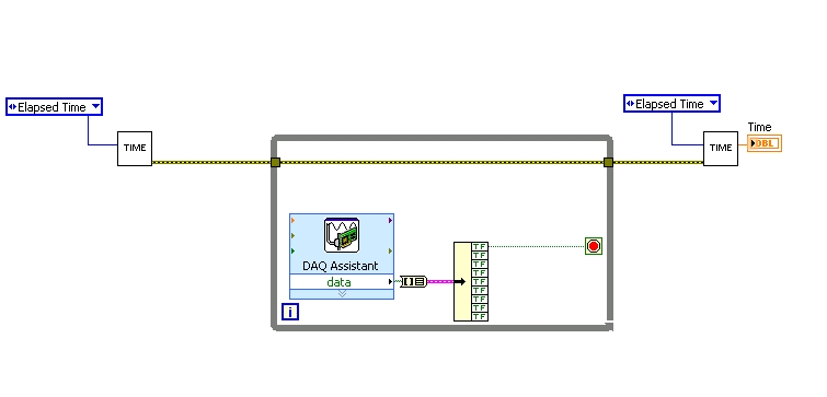
Measure the time between two digital pulse
Hello
For a non-critical calendar application, I need to measure the time interval between consecutive TTL pulses, ranging from the order of 0.5 s for a few seconds, with a low accuracy of +/-10-50ms. The interval being measured varies between the rising edge of the first pulse and the front of the next and so on.
I have several input lines I need to deal with. Because it's a critical machination low cost, I don't want to use digital counters for each line, so I work with an acquisition of data USB6008 and have connected the input rows TTL on the digital inputs of the device. Avoiding will be sufficient.
I found a good example of VI on discussion forums that does almost the same thing, only it uses instead of the DAQ Assistant user input. The VI works including the time the program going on in a while loop. I replaced with the DAQ Assistant output (a channel) user input in the hope that it is still work.
When I run the program in "run once" mode, it seems to work perfectly. However, in "continuous run" it measures only a very small interval, probably just the time between two samples. I think it has something to do with the help of a while loop in combination with the DAQ Assistant. Anyone who has any suggestions how to solve this problem?
Thank you!
OK... first of all, you should never use the button "run continuously. I wish that NEITHER would be to eliminate it, but told me that it is sometimes useful for debugging. If you want your program to run over and over again, use a while loop with a stop"" button.
If I'm reading your code correctly, you make your initial moment, and then collect data from data acquisition. When one of the channels is "T", you stop your loop and the end time of capture. (By the way, why you convert your table to a cluster? Why not just index the appropriate channel in the table directly?)
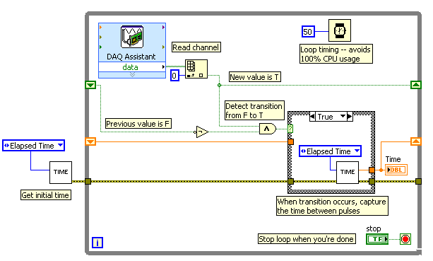
Since you want to capture the time between two consecutive pulses, you need to know when a transition has occurred... i. e when your digital line went from F (no pulse) to T (pulse start). This will give you your forehead. Right now, all you're doing is looking for a value T - so you have no way of knowing if you are looking for to the previous impulse again, or a new impetus. You also burn 100% of your processor with the way you have your programme in place.
You need a small loop delay so that your VI is not 100% of your hogs CPU time. Given that you can live with an accuracy of 50msec, what I suggest that you use.
See attached picture for you give an idea of how to implement. He will probably need some refining operations, but it should point you in the right direction.
I hope this helps.
-
How to set the time between workstations and Server 2008 R2
Hello world
I have problem with my Server 2008 R2
all the workstations on my company doesn't synchronize the time on the domain controller
I tried many ways to set up automatic synchronization via command prompt (Net time) and its does not work
Please help me configure the time between the DC and the workstations
Thank you
Windows Server forums:
http://social.technet.Microsoft.com/forums/en-us/category/WindowsServer/ -
Try to shorten the time between songs
Original title: Media Player
If I am using windows media player and create a list of songs to play how shorten the time between songs, so we can finish and the next songs will start immediately?
Hey BillTolbert,
Unortunately, there is no settings to do such things.
It's common sense, the songs will be the next song to play won't take long to play.
The next song begins to play as soon as the first finshes.
Hopefully this should clarify your doubts.
Good luck!!!
-
How to set the time between slides in a slideshow (iPhoto, el capitan)
How to set the time to say - 5 seconds or 20 seconds - between slide show photos in iPhoto. I use el capitan.
See the Settings button at the bottom right of the toolbar (at the bottom of the slide show). Click on it and you have a small window with two tabes, refers to all the slides, the other to the selected slide. You can make your choice
-
How can I measure the time between the two edges of successive increase, using digital input...
Hello
I'm trying to measure the time in seconds between each two successive rising edges on a digital input.
So far I managed to detect the rising edge, increment a counter at each rising edge and take the time during which the increase is edge
all I need now is subtract edge currently rising from the previous era of edge rising to calculate (T), which can be 1/frequency and display in real time for the user.
but I do not know how to do this
Can someone help me please!
Note: while I am in a position varies between 200 ms - 2 seconds
-
change the time between each photo in movie maker vista
I am doing a slideshow using vista movie maker. I added music and it is great. BUT I can't change the length of time between each picture and the duration of transitions. I tried tools / options / and I can change out there, but it does not apply to my project. I also tried to do it manually but still no luck.
Any help would be most appreciated.
Maybe the following will help:
The change of setting to: Tools / Options /.
Advanced... tab applies only to the added photos
to the timeline * after * you change the setting.If you switch to view "Storyboard" and select
all the pictures in the form of batches (select one and the type...
CTRL + A)... you can add the 'Speed Up, Double.
or "Slow down, half" effect of changing the
duration. Simply select all clips / right click
the effect on the menu... Choose...
Add to storyboard table.'Speed Up, Double' cuts the duration of half.
"Slow Down, half ' double life.
These effects can be added up to six times.
If you need finer adjustment...
the info may be useful:To the timeline, you can change the
the duration for each picture manually. Drag the
Garnish handle left or right to increase or
reduce the duration. You can see a
Tip displaying the change.Or... just to redo the project after changing
the long-term: Tools / Options / Advanced
tab.With respect to Transitions, see the following article:
Windows Movie Maker Vista - add transitions and effects to pictures and
video in Windows Movie Maker
http://Windows.Microsoft.com/en-us/Windows-Vista/add-transitions-and-effects-to-pictures-and-video-in-Windows-Movie-MakerIn some cases, you can add a transition
to every other picture... What follows... explains why:This happens when the Transition is
the same or greater than the length of the photo.
This setting must be entered before add
clips on the timeline.Tools / Options / Advanced tab.
To add effects or Transitions to all clips
at the same time... Follow the following steps:Go to the table of Storyboard view.
Select all images. (click left one)
and type... CTRL + A).With all the images selected... go...
Transitions video and do a right click the
You want to add, and then click on...
Add to storyboard or type table... CTRL + D.It also works with the effects.
Effects...
The duration of the effects is not adjustable. As a work around
to extend a fade in from black, you can insert a black solid
.jpg that you can create in most image editing software.(FWIW... the intensity of certain effects can be increased
If you right click on the picture and choose... Video effects...
You can add up to 6 cases of effect)In Windows Paint (for example)... Open the photo / right click
the black square in the color box and type... CTRL + SHIFT + N.
(if you do not see color box... type... CTRL + L)(1) to save a photo...
(2) go to... File / save as...
(3) select a backup location...
(4) enter a new name (which guarantees that your original picture is
not overwritten),
(5) choose a format...
(6) left click... Record. -
Estimate the time between two computers
Hello, everyone.
I want to develop a program for communication between two ip addresses:
IP1: 192.168.1.100
IP2: 192.168.1.101
Suppose IP1 is the server IP2 is the Viewer, then I want to put in place a program to estimate the elapsed time for IP1 contact IP2, but I don't know how to do.
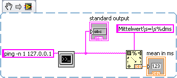
Also, I want to display the elapsed time for the connection (which varies due to fluctuations in the internet), performing actions such as continuously 'ping' the receiver from the server. Can someone show me the way to achieve this? Thank you very much.
Best regards
yukfai88
Please do not shout

How about using ping?
Insert the output in an analysis of string to read the value you need. Sorry my OS is in German so you have to adapt ;-)
-
Delay between VISA W/W and chain problem
Hello
I'm working on the documentation for the other VI. I had a question about the time between VISA W/W. I was wondering why we cannot put all the strings in an entry VISA and what is the purpose of having two writing here and the wait time of 0.1 s is critical?
I had the problem of the chain where you can find it with three question marks of labelling in the .png file, I want to see what CHANNEL I get here, but when I add
Here, an indicator of what I've got is a number instead, why?
BTW, what is the meaning of integer 70, I knew is the number of bytes of data to read, but I got the exactly 70?
Thank you
The delay does absolutely nothing. I suspect that the original programmer intended to give time for the instrument to the installation before taking a reading. Demand of the measure and the delay come however in parallel.
The number of bytes requested is a somewhat random number. You just want something big enough to get all the data in the buffer. It might as well be 1000 or 10000. Playback will be automatically terminated with EOI is affirmed by the instrument.
The indicator displays a string, but the string is obviously digital before being converted into a DBL.
-
Hallo,
I use the following system:
- OR PXI-1044 with controller NI PXI-8109
- OR PXI-2564 switch module to turn on the monitor of my test device
- Data acquisition multifunction NI PXI-6259 to measure the signal that responded to the questionnaire jump
The two cards are the same - PXI trigger bus. For both, PXI-2564 and PXI-6259 I use DAQmx to set the reading and writing of the channels.
Now, I want to measure the time between the digital output, my unit turns and the analog input, which measures the response of my system.
I can't do work by myself, please help me!
I thank Ludwig.
Hi Ludwig,.
If you can't give us any VI we have difficulties with to help you.
Because I Donat knowledge how your program is mounted it is not easy to know where you should enter signals.
Here's a question similar to yours:
http://forums.NI.com/T5/LabVIEW/best-way-to-measure-time/TD-p/178704
and 2 external links:
http://www.ehow.com/how_8698983_measure-time-LabVIEW.html
http://objectmix.com/LabVIEW/385152-how-can-i-use-LabVIEW-measure-time-between-analog-pulses.html
-
How to set the time difference between each data when using keithley 2400 scanning
Hello friends,
I use scanning Keithley vi the extent of SCANNING and acquire vi. I want to measure the voltage for each step and a pause between each two data, so I need a delay between each I step.
I'm a starter to use Labview, thank you very much for your answers.
Perry
As Dennis says, if you use the built-in scan function, you will need to consult the manual. See Section 10-16 (this is page 10 of article 16, only paragraphs not but 10, 16) for the manual Keithley 2400.
The Keithley 24xx series has a speed of measurement in units called PLC (Power Line Cycles). The default speed is 1PLC, which means a measure is taken with each cycle of line 1 power supply or 1/60th of a second (16.67ms). 24XX can range from 0.01 PLC (all 0.16ms) 10 PLC (all 166.6ms). The faster you measure, the less accuracy you get.
To programmatically set this value, the command is
 ENSe:CURRent:NPLCyclesENSe:VOLTage:NPLCycles
Depending on what you are sensing and where
is the number of controllers from 0.01 to 10. Another factor that will determine the time between data points is the cycle SDM. These are more complicated, look at your Keithley manual for more information. Look at article 6 and article 11 for more information.
Note:
PLC times are based on a cycle of 60 Hz US.
Maybe you are looking for
-
OS 9.3.1 - ibooks blocks viewing of pdf files
Just bought my first ipad... Play with her like crazy... Unfortunately, there are a lot of bugs in the operating system. And here's one, saved a PDF of Firefox in iBooks. Now ibooks does not work. Very disappointed.
-
Toshiba 39L4353DB Youtube app chops on the last 30 seconds of the video
Hi, I'm using the Toshiba 39L4353DB smart TV. The Youtube app plays the video correctly, but always ends the video about 30 seconds before the end of the video. This happens to every video played. This question is not moved before the last automatic
-
17 - g015dx: 17-g015dx system recovery
Hard drive gone bad. Replacement screen and got the "install operating system." Cannot find any operating system or on-site recovery usb to order. IM dumb with computers and don't know what to do or where to look next.
-
HP Photosmart A712: HP Photosmart A712 leaves 1/2 photo print
Photography first printed beautiflly, but eventually the group stopped 1/2 way through the cycle. I don't remember changing anything whatsoever. I tried to find a updated driver without success. Thanks for you help.
-
Recently, my windows xp had malware and I was wondering if my emails on outlook express would always be there when I fix it? My email is the Charter. Thank you!!!