Need the block diagram of NOR-SCOPE Soft front Panel
I doubt that the code that is available - it can not even be written in LabVIEW. Examples of NO-SCOPE that are provided with LabVIEW (look in the Finder example under hardware input and output-> Modular Instruments) illustrate all the available functions, and it can be an example that works as a starting point for you.
Tags: NI Software
Similar Questions
-
Usability is NOR-SCOPE Soft Front Panel for the PXI-5154?
I am plans to use the PXI-5154 with his NO-SCOPE Soft Front Panel in a product to test instrumentation. Our past experience, our users need an on-board scope that is easy to use which does not load the CPU. In most cases the scope will be used to check a transitional type of pulses. So, the amplitudes and rise times are essential to ensure compliance with ISO standards. The ability to capture, store and recall traces of reports is important, as well as the ability to perform simple and reproducible follow-up measures. We don't expect our users to have to program the scope; "give me the waveform.
Does anyone have any comments on the usability of the NOR-SCOPE Soft Front Panel? How to compare with other soft scopes?
Hello!
The scope Soft Front Panel is very user friendly and able to load/save waveforms, Load/Save settings and make the scalar measures. I've attached a screenshot of what the front soft worn looks as well as a link to a help document on the high speed digitizer HELP. Information on the scope Soft Front Panel lies in this document and can be found under the tab content in the configuration tree (NI - Scope Soft Front Panel help).
Help of digitizer OR high speed
http://digital.NI.com/manuals.nsf/WebSearch/2123F564C6DE7B27862574DE006915DE
-
LabVIEW version of the source code of the NOR-DCPower Soft Front Panel
I work with an SMU NI PXI-4130. There is a front panel soft exe called the "NOR-DCPower Soft Front Panel" that can be used to control the instrument. I was wondering if there is a version of LabVIEW source code for this driver?
Jim,
as much as I know there is no LV source code provided for the Soft Front Panel. But there are a few examples of LV, which will be close to the characteristics of the SFP. So I suggest to you to dig in the examples you find in the Finder of the example.
Input and output hardware > Modular Instruments > NI-DCPower.
hope this helps,
Norbert
-
OR-SCOPE Soft Front Panel errors
I can't capture a square wave 10 kHz using NOR-SCOPE FPS. The error that I get for the manual config and auto-setup is-200580 requested is not a valid Vertical offset.
Max test panel can capture the signal without errors.
My setup is PXI-5154 Slot3, chassis PXI-1031DC, Windows Vista, LabVIEW 2009, MAX 4.6.0f1. Entry test square wave 10 kHz, 4Vp - p connected to Ch0 BNC 5154.
Hi bmann,.
What is the descriptor of the resource able & Automation Explorer (MAX) for this device? Is it the same as other devices that were previously on your system?
The 5154 can't stand the vertical offset, but other devices (for example the 5152) support vertical offset. The NO-SCOPE Soft Front Panel (SFP) will use the resources descriptor to identify devices. If no configuration is not found for a device with a particular resource descriptor, then the FPS will run an automatic configuration on the device. However, if the FPS is a previous corresponding configuration with the same resource descriptor, it will attempt to use this same configuration. This is where I believe you can receive the error.
If you have a 5152, you can check the "vertical offset" parameter in the "Device setup" window - looks like this is the setting that attempts to commit to the 5154 the SFP and the NOR-SCOPE driver is throwing this error. For a 5152, this parameter should appear, but the 5154 this setting should not appear.
Could you try to re - appoint the device in your system for something unique?
Let me know if it helps. If not, it could be another question - let me know what version of the driver NOR-SCOPE you have installed if this is the case.
-Andrew
-
OR scope Soft Front Panel fails to load
Hello
I use the scope Soft Front Panel OR with my USB NI 5132 for some time successfully. However, recently it has stopped working completely - seems to load a bit then fails before you even open the screen. The same thing happens in MAX I did all the updates critical, uninstalled then reinstalled NI Scope, uninstalled Labview (the only thing I had changed after the last time, I know that it worked successfully) and checked the nitaglv.dll library was in the right place according to this post: http://digital.ni.com/public.nsf/allkb/63739991438EC593862579C6007301EC
So far nothing's worked. I NI SCOPE 4.0 and NI-VISA 5.3.0 installed, and the computer could see successfully the digitizer USB 5132 Max after the relocation OR scope, well that the flexible façade does not always load and making the Panel test Max also does not.
I have attached a picture of the screen to load before it disappears so that could provide clues.
Suggestions?
-
Hey!
How can I include the "impedance" and "Probe atténuation" options at the front view of NOR-SCOPE?
Now, this option run "Edit-online Device Configuration"!
Thank you
Patrick
Hi Patrick,
the soft front panels are demo applications for our various modular instrument drivers. We do not distribute their code, nor can you change their GUI.
If you are programming with LabVIEW I would recommend that you build your own version of a scope to start with an example of our example search tool (help-> find examples). A good starting point would be the Acquisition of niScope configured EX example which also gives you a good overview of how to use the scope pilot.
If you have more specific questions do not hesitate to ask!
Best regards
Peter
-
Options OR Scope Soft Front Panel
Hey!
How can I include the "impedance" and "Probe atténuation" options at the front view of NOR-SCOPE? Now, this option run "Edit-online Device Configuration"!
Thank you
Patrick
-
What is the best way to keep the block diagram / cleaning of façade?
Hello
I'm relatively new to Labview so I'm not able to say if I'm overloading my programs or make my too crowded block diagram. I was wondering if there was some ways to tell if I can simplify my programming just by looking (perhaps only experience contributes to these things)?
I enclose my VI here. Currently, she is able to monitor the voltage and current of two engines. On the screen, you can see an indicator with the voltage and current values and there are cards that can display signals of different engines with a menu drop-down.
The façade is pretty clean, in my opinion of novice, but the block schema seems messy to me, just at the first glance. I foresee a problem occurring in the future however. In the future, I will have the VI to monitor 50 engines globally. All of the programming will be the same as the one I have now, but it will have 50 indicators and unfortunately 50 times just about everything. I would like to avoid this, but I don't know how I did.
I use a USB-6009. I use its four differential inputs to monitor the voltage and current of the two engines. In the future, I will get more units DAQ (25 in total because 2 motors can be monitored for each data acquisition). The new Renault will help will help with more resource space, but I think things complicate with the added option of 24 more Assistants of data acquisition (as used in my code).
Thanks for any help you might be able to provide!
Usually, it is above all the experience that will teach you the best methods for making your code to do pretty. I don't know anyone who is proud of his first application of claws. There are some resources out there to help with best practices, as that group on ni.com, but you will learn most of your own development.
Your façade is superb. FPs in general really are to you. You can do it as ugly or pretty as you want. When you have a few controls in duplicate and the Group of indicators, you should use clusters and berries to simplify. You can use a bit of cleanup in this regard, but not much. In addition, I personally hate read red text unless it is a warning any.
Your block diagram could use a little cleaning in a sense of modularity. You have a lot of repeated code, which you might consolidate in to a Subvi, which is used in multiple locations, or in a loop For. A general rule is to keep your block diagram within a single monitor. You should not scroll. Your application is quite simple, so it is difficult to BUMBLE

Here are a few details on your block diagram:
- Click with the right button on your devices on the block diagram and uncheck the "display as icon". You are welcome.
- Operations on each waveform "(x*2-4)" / 16 in double ": create a Subvi and/or run the waveforms through a loop."
- You do a lot of 2-element arrays and then indexing. Just replace the ones that have a Select node based on digital.
- All your code runs every time, including the knots of your property at the bottom, which is not necessary. As you learn LabVIEW architectures, you will learn how to get around this with the initialization and the output of code, but for now, you should put a case around those structure for only when the engine numbers change.
- I don't know how you're timing your main loop, but you should put a delay in there because you don't need the DAQmx node shoot as fast as your CPU will allow.
There are videos of intro free that you can watch to learn what OR think in terms of coding and teach you some of the basic features and such. Here's a three-hour course, and here's a six-hour course.
-
How to find the position of the VI icon currently run on the block diagram of the appellant
Dear forum,
I am currently trying to use a LabVIEV VI as a simple sequencer: several (very slow) actions must run one after the other. Each action is represented by a Sub - VI, some actions are executed several times. My task is to view the Subvi somehow executing.
My first intention (just manipulate the icon of the VI running with 'Icon.Get VI as Image data' / 'Icon.Set VI of Image data' invoke nodes) has failed, because it changes all instances of the VI icon. If you use the same VI several times, all these VI icons are changed (see here: http://forums.ni.com/t5/LabVIEW/How-to-change-animate-icon-of-currently-running-VI/m-p/3120754/highl... )
My current approach is to use an image of the block diagram (with "VI: block diagram: get resized Image ' call method) in a picture of the front panel control and working within this control. But for this I need to know the position of the icon of the VI running. I know that I can assess the limits and Position via the properties GObj, but how to find the VI running (note that a VI can be installed several times on the block diagram, so the name of the VI is not unique)? IMHO the easiest way might be if a VI might find its icon on the block of the appellant diagram itself when it is run...
It is clear that this position is not yet the position on the photo, but this conversion is a small piece of work...
Kind regards
cpschnuffel
-
How can I activate on labels in the block diagram, but not on the front panel?
This question may have been asked before, but searching the Forum did not.
In LabVIEW 2010, I have 16 indicators of chain on the front panel. I can't have the label for each Visible on the front panel, so I turned it off. But in the block diagram, I need distinguqish one of the other, so I need to make the label (name) visible.
In the block diagram, if I select indicators Sting all together and go to properties and make the label visible, it makes visible labels on the front but not visible in the block diagram. What good is that?
How the help of labels (name) of the indicators String visible in the block diagram, but not visible on the front?
dbaechtel wrote:
This question may have been asked before, but searching the Forum did not.
Don't remember already asked this question and get help in this thread?
Have you tried the things I said in that thread? How did they not work?
Right-click on the terminal of BD and make visible > labels.
It probably will be the FP control show its label as well. Then go to the FP control, right-click and go to Visible > labels and uncheck the box.
The terminal of the comics will have a label, and control of the FP will not.
-
In LabVIEW 2010, I have a Def Type control i.e. a Cluster with several other controls within the Cluster. Apparently, the references to the controls in the block diagram are based on the order that the controls have been added to the Type definition command. The side effect of this is that if a control is removed from the command of Type definition, many of the done Variable reference in the block diagram or now either broken, or worse still, refer to wrong control in the Type definition. These problems are quite difficult to find and fix.
Comment: If you create a control of Type definition and make a Cluster. Now add any controls to the Cluster in an order, let's say A, B, C, D. Their types does not matter. Now use the Type definition in one or more controls on the front panel. In the block mark references to controls inside the Type Def would control on FP. Now return to the Type definition and remove the command B of the definition of Type. Now, lots of errors appear. Broken links. But worse still, you see old references to B that now refer to C and old references to C are now referring to the old references to D and D are removed altogether, etc.. This side effect is much more errors, broken links and misreferences than expected otherwise.
How add and remove controls anywhere in a Cluster in a Type definition, at will, without creating a whole bunch of errors in program, broken links and misreferences for controls in the Type definition that have not changed?
-
Why the block diagram is disabled?
What do I do now? Please, look at the attached picture. A VI that I use as a Subvi in various different programs suddenly started looking like I had used the application builder to create an exe out of it (but I don't have!). The only options are Start and run continuously, and the block diagram is disabled. What I did to get into this mess? How to cancel everything that I did, so I can edit the schema-block again? For any help or suggestion would be greatly appreciated.
Thank you!
You have somehow managed to record without a block.
Go back to the last working back up and start from there. You have backups, right?
Lynn
-
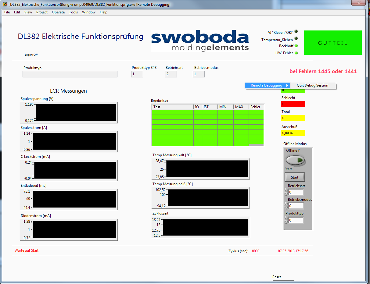
Remote debugging active but no access to the block diagram
I have an executable running on a target that I want to debug. I enabled debugging in the build properties, I enabled debugging in vi properties. I can connect from the development computer to the exe.
But the option to switch to the block diagram is simply not there (see photo). I know I am a first not who has this problem but I couldn't find an answer.
Without being able to see the block diagram, a 'debug function' is totally useless!
If anyone has an idea it would be greatly appreciated. Thank you
Hi peter,.
It is a known problem and a request for Corrective Action (130070 CARS) was created and reported to the Department R & D. looking at through the notes in the CAR, he must fix it in LabVIEW 2012.
Workaround solution: Debugging applications with menus on bar
-
Impossible to select and place the Instrument Driver VI icons on the block diagram
I am trying to automate some of the RF measurements using a Rohde and Schwarz Spectrum Analyzer. I downloaded the Rohde and Schwarz spectrum analyzer pilot named 'rsspecan' version 2.6.1 for Labview on Rohde and Schwarz site to use in my version of the software labview 7.1.
I copied the files in the appropriate folders in the Labview software on the C drive files. I am able to access those files through the functions---> Instrument I / O---> range of Driver of instruments in the Labview diagram, but when I select the VI icon that I want to put, I am unable to place it on the block diagram. Instead of hovering under the cursor by clicking on the VI icon, by clicking on the icon of the VI has no answer whatsoever.
Any help would be greatly appreciated.
Thank you
Thank you very much for the help.
So, is there a way to get the above mentioned pilot online Spectrum Analyzer, which will be also compatible with LabVIEW 7.1, so that I don't have to go through the conversion of version Board?
Thanks again,
Vivek
-
Third-party tool to draw the rectangle on the block diagram
I know he was once a third party tool that allowed me to draw a rectangle of Nice double border on the block diagram. Yes, it's the not the front panel block diagram. It was very useful to make annotations and designating functional groups. Does anyone know what this could be? I installed Package VI Manager and went through everything I can think of without finding her.
Unfortunately, the documentation for those modules potentially very useful is poor. The 'Get info' is terse point of unnecessary and by clicking on "Product Home Page" rarely gets you more than a logo, not informative. Surely there should be more details somewhere.
I don't know what you're referring to the tool. What is this logo? Maybe someone can recognize.
What is the problem with the flat frame?
Maybe you are looking for
-
Portege R830 - fingerprints fingerprints are more recognized
Hello Last week, I bought a Portege R830. I registered my 2 index fingers and everything has worked fine for about 2 days. Now when I put my index fingers, the utility no longer recognizes my impressions, neither one. How can I delete the prints and
-
Satellite C850-1LK does not turn
Hi people, I'm trying to get a Satellite C850-1LK to turn on without success. When I connect the PSU it show initially an orange light indicating the power supply is connected. After a while of"charge" that the light has now turned white. Press and h
-
Fingerprint sensor has stopped working properly
Since 2 days ago the fingerprint sensor is constantly not to recognize fingerprints, does work don't not or not having not even a 'Fingerprint' option in the Security menu at all. And when it shows up, I can not add new prints because it shows a read
-
How can I see what devices are files on network sharing domestic?
I have a ps3 & Xbox which can share files stored on my pc but I can't seem to find what/how you would you find... ? I am a novice, so go easy on me! :-/
-
PC will not boot or start the recovery console
Windows XP 2004 AMD Athlon XP 3000 +. AVG 8.0 My friend tried to jailbreak his ipod. Now his PC will not boot the OS. It will go to the screen with the options to choose each time you start upward into the safe, normally last good known etc.. Choose