New effects of resolution monitors on block diagram
I recently got a new PC with display quad outputs IT.
I had new monitors with different resolutions, since the old monitors that I used.
Everyone noticed when opening old projects on a new presentation available to block diagram to become very different?
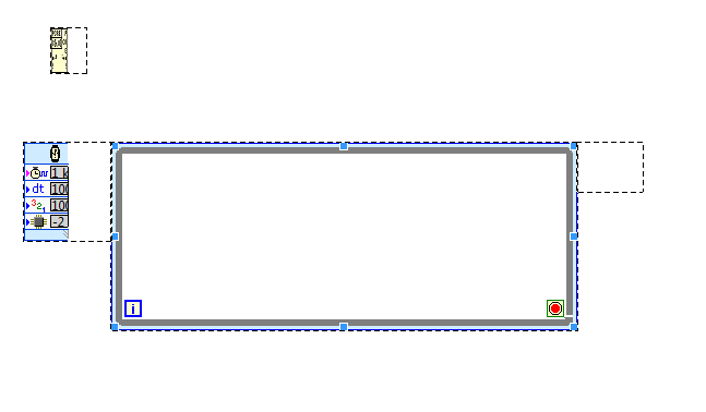
For example, look at the attachment, look how big is the area "Group by name", and how it has consumed all the objects around it.
There is a font size setting that must be set to ' small (default) 100%. Make sure that it is not defined for medium, 125 or more than 150%.
Tags: NI Software
Similar Questions
-
Clean using SubVIs block diagram
Hi guys and welcome to my first post!
I m a bit new to labview, so be a little patient, if I do not understand everything immediately

Im working on an existing program that is used to control an MCU on BabyLin on my front, although I have a visualization to see live changes to the system. The program works very well so far, but I m trying to clean up the block diagram. This should be done by subvis, right? I ve read a lot about the size of the block diagram should not increase my screen. Well, im at a length of about 3 x 2 screens (24 "!) after trying to use subvis and to shorten the distances between structures. The only things remaining are huge amounts of local variables and references (they existed already before I got to know the program), mainly for viewing. If I create a Subvi part containing the people of the country, it will change the references that does not make the program more readable (and small), and I guess I can't put a new Subvi on references + Subvi.
You have any ideas what to do? I hope that I forgot something, otherwise, do not hesitate to ask.
Kind regards
Leo
Bob_Schor wrote:
To get a handle on the structure of your high-level code, write down (as if you were telling your boss or tell your wife - who knows, they might be the same person!) that you are trying to do. Keep it pretty General. You specified a number of steps? So maybe the top level should be a State Machine, or a message in queue manager. Describe you something that works at a constant speed, generating data that you have to manage "on the fly"? Maybe it's a design of producer/consumer.
You have a lot of initialization? Put in a Subvi, bring the 20 son out in a bundle (it's "Boss-word" for a Cluster). Your main program must have a few loops, with values that persist (possibly changing) during the program running in Shift Registers near the top of the loop, with tables and Clusters used to keep related items "consolidated".
Not too bothered by the size of your routine - I recently downloaded a monster 50-monitor the Forums (I did not even try to understand), up to 6 monitors is nothing!
Let "encapsulate the function" and "hide details" to be your guide in the reflection on the creation of the screws.
Bob Schor
To develop on the analogy of Bob, each talking point can be a Subvi. In other words, code group associate subVIs. The advantage of this is that it is much easier to solve problems because all errors will be localized to a Subvi. Errors no longer Chase around the block diagram. I guess you can use your current VI as an example of what NOT to do on the block diagram.

-
What is the best way to keep the block diagram / cleaning of façade?
Hello
I'm relatively new to Labview so I'm not able to say if I'm overloading my programs or make my too crowded block diagram. I was wondering if there was some ways to tell if I can simplify my programming just by looking (perhaps only experience contributes to these things)?
I enclose my VI here. Currently, she is able to monitor the voltage and current of two engines. On the screen, you can see an indicator with the voltage and current values and there are cards that can display signals of different engines with a menu drop-down.
The façade is pretty clean, in my opinion of novice, but the block schema seems messy to me, just at the first glance. I foresee a problem occurring in the future however. In the future, I will have the VI to monitor 50 engines globally. All of the programming will be the same as the one I have now, but it will have 50 indicators and unfortunately 50 times just about everything. I would like to avoid this, but I don't know how I did.
I use a USB-6009. I use its four differential inputs to monitor the voltage and current of the two engines. In the future, I will get more units DAQ (25 in total because 2 motors can be monitored for each data acquisition). The new Renault will help will help with more resource space, but I think things complicate with the added option of 24 more Assistants of data acquisition (as used in my code).
Thanks for any help you might be able to provide!
Usually, it is above all the experience that will teach you the best methods for making your code to do pretty. I don't know anyone who is proud of his first application of claws. There are some resources out there to help with best practices, as that group on ni.com, but you will learn most of your own development.
Your façade is superb. FPs in general really are to you. You can do it as ugly or pretty as you want. When you have a few controls in duplicate and the Group of indicators, you should use clusters and berries to simplify. You can use a bit of cleanup in this regard, but not much. In addition, I personally hate read red text unless it is a warning any.
Your block diagram could use a little cleaning in a sense of modularity. You have a lot of repeated code, which you might consolidate in to a Subvi, which is used in multiple locations, or in a loop For. A general rule is to keep your block diagram within a single monitor. You should not scroll. Your application is quite simple, so it is difficult to BUMBLE

Here are a few details on your block diagram:
- Click with the right button on your devices on the block diagram and uncheck the "display as icon". You are welcome.
- Operations on each waveform "(x*2-4)" / 16 in double ": create a Subvi and/or run the waveforms through a loop."
- You do a lot of 2-element arrays and then indexing. Just replace the ones that have a Select node based on digital.
- All your code runs every time, including the knots of your property at the bottom, which is not necessary. As you learn LabVIEW architectures, you will learn how to get around this with the initialization and the output of code, but for now, you should put a case around those structure for only when the engine numbers change.
- I don't know how you're timing your main loop, but you should put a delay in there because you don't need the DAQmx node shoot as fast as your CPU will allow.
There are videos of intro free that you can watch to learn what OR think in terms of coding and teach you some of the basic features and such. Here's a three-hour course, and here's a six-hour course.
-
In LabVIEW 2010, I have a Def Type control i.e. a Cluster with several other controls within the Cluster. Apparently, the references to the controls in the block diagram are based on the order that the controls have been added to the Type definition command. The side effect of this is that if a control is removed from the command of Type definition, many of the done Variable reference in the block diagram or now either broken, or worse still, refer to wrong control in the Type definition. These problems are quite difficult to find and fix.
Comment: If you create a control of Type definition and make a Cluster. Now add any controls to the Cluster in an order, let's say A, B, C, D. Their types does not matter. Now use the Type definition in one or more controls on the front panel. In the block mark references to controls inside the Type Def would control on FP. Now return to the Type definition and remove the command B of the definition of Type. Now, lots of errors appear. Broken links. But worse still, you see old references to B that now refer to C and old references to C are now referring to the old references to D and D are removed altogether, etc.. This side effect is much more errors, broken links and misreferences than expected otherwise.
How add and remove controls anywhere in a Cluster in a Type definition, at will, without creating a whole bunch of errors in program, broken links and misreferences for controls in the Type definition that have not changed?
-
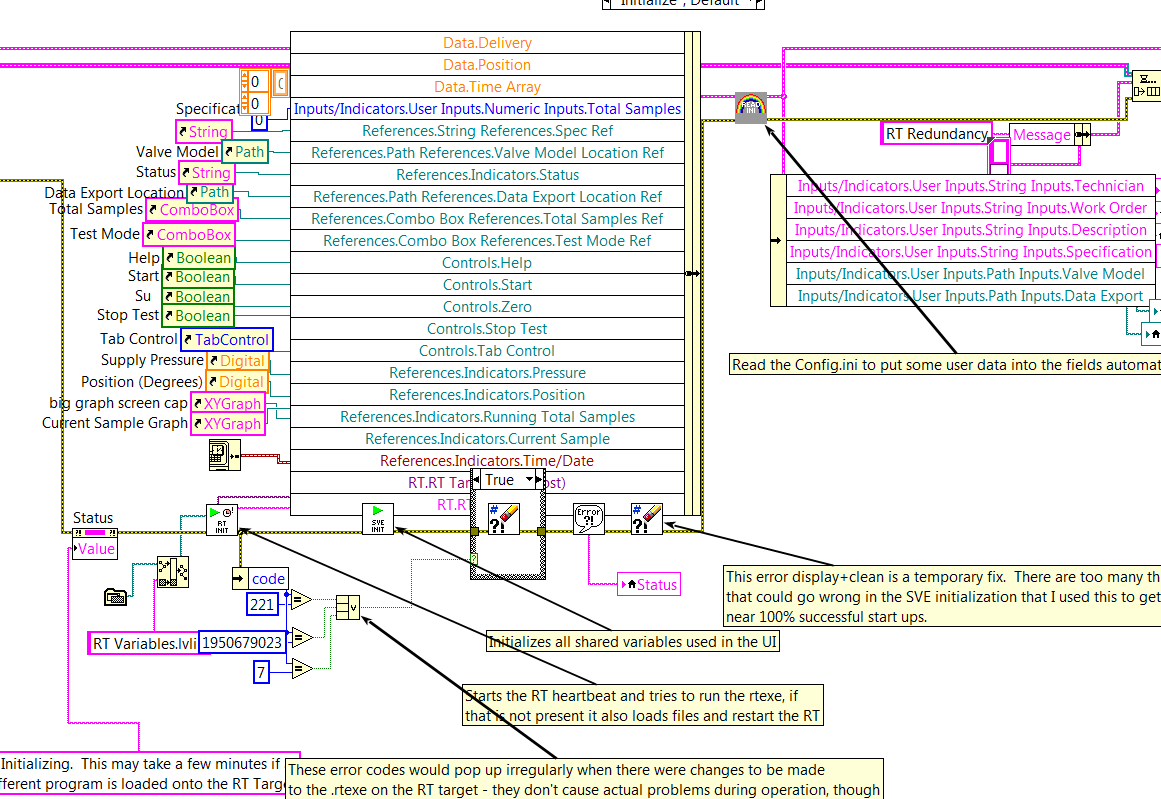
I have a double 2D chart I want to decimate continuously using the ".vi (continuous) Decimate" located in the range of Signal Processing. This VI is set on reentrant preallouee clone because it uses a FGV to save the State of the call to. What I could do, but do not want to, is having a huge index table and wire 20 + 1 table of DBL to 20 + unique VI instances decimate to ensure that each have their own data space and no 'cross-talk' doesn't happen, then 'picture of generation' all back after the fact.
I'm almost certain, there is a much cleaner way to do it with only one instance of unique block diagram of the VI decimate using techniques of the call by reference. I found my way to this link: Preallocated-Reentrant-VI-within-Parallelized-For-Loop that talks about something similar. After reading pages of four and the detailed help about the function 'Open VI référence' my head is spinning again on what option I want to spend (0x08 or 0x40 + 0x100) to ensure that whenever a slna 2D table come in, each of them is decimated by using the same clone that was used the last time it was called.
Although the DBL entry 2D array always has the same number of lines, now, it is not always in the future this number and ideal would not force me to create several references strictly typed in VI decimate that will have to change as grows the number of rows in the table 2D static DBL.
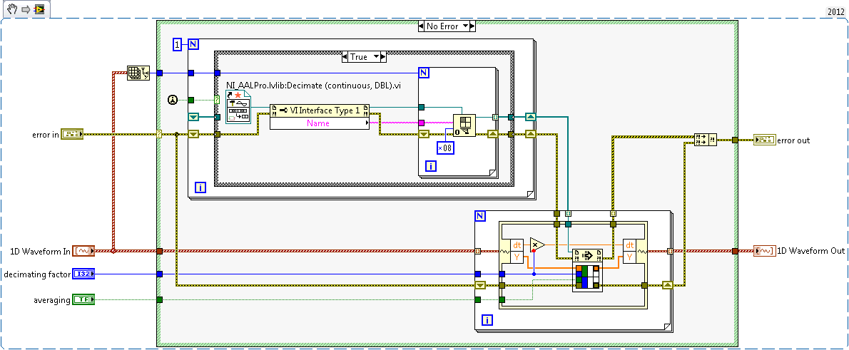
Anyone ready to set up an example VI that takes an array 2D arbitrary of DBL as input, decimating each line using the same clone independent of the "Decimate (continuous) .vi" and outputs the newly decimated 2D Array of LDM? Assume that each line uses the same factor of decimation and 'Sprawl' set to False.
Necessity is the mother of all invention and since it upsets me when I read a post that has a similar problem with no resolution, I felt compelled to post mine here. I'm sure it's better I can do within the current state of LabVIEW. The only question I have is what happens if I put the call by reference for loop be parallelizable? That trash completely the nature of 1 to 1 of what I intended?
-
Corrupt the VI block diagram (try to view the BD accidents LV)
The attached corrupt version 2010 VI in the room is '8810A control.vi.' I put work a few days into it, so it would be nice to get it back. I can open it fine to display the front panel. When you try to view the block diagram, an outline of the BD window appears and freezes LV. Usually, after a few moments, LabVIEW itself disappears completely. No error message; no sign of it in the taskbar or any where. I tried to save the VI to a previous version, but LV will receive an error. In trying to "Double hierarchy to the new location", I get a popup saying "LabVIEW: file generic i/o error.» I then did a copy of VI, open and tried to delete everything from the face before completely. Still can not go to the BD.
I think that what caused the error was when I accidentally clicked my mouse button that I arrived to move the cursor quickly through the BD of this VI. I couldn't tell if it hit or moved something on the comic. I don't remember for sure, but I think that at this time there LV froze and I had to kill him and restart. After happened yesterday, I moved on to work on other screws which have not been affected. I guess I'll have to recreate (because I had not yet created backups).
 in the future, I hope that I can remember save projects at least twice a day. I've used Mercurial and it works well. Hard lesson learned.
Try this. I saved to LV9, opened with LV9 then did a cleanup of comics.
-
Programaticaly inserting block block diagram.
Hello to all 2!
I wonder if there is a way to programaticaly insert a new block in an existing diagram.
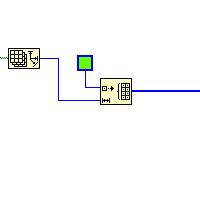
Take a look at the attached vi to see what I mean.
So... When I click on an image of the corresponding function is inserted in the block diagram, having as inputs the two controls.
Is there a way to do this or is this just wishful thinking?
)Thank you very much!
It is possible to programatically manipulate the block scheme by obtaining a reference to it and operating on it with the use of the property and call the nodes. It's scripts of VI. You can write code that uses scripts in LabVIEW 7.1, but it can be imported in more recent versions of LabVIEW. This function is not supported by National Instruments. Being that it is not supported, I would not recommend research inside if you develop a code for a customer.
This should help you get started:
http://forums.lavag.org/VI-scripting-Readme-first-t1207.html
http://forums.lavag.org/LabVIEW-VI-scripting-F29.html&s=3fea8247be8d214406abf99a30e64e94 is a forum where you can ask on the scripts, being that it's about undocumented.
Welcome to the dark side, good luck in your journey and watch the rusty nails that you rummage through the attic of NOR. (lol sry, cheesy feeling on my lucnh break)
-
Is any way to put a VI that I placed on a palette in the menu functions to create a copy of it self when I place it on the block diagram?
My example is as follows. I create a palette for a messaging configuration. The 'send message', 'message' and so forth will work normally with just called when necessary. But 'Create queues messge' must be specific for each instance, because I'm going to create a different number of queues each time I use it. (See system messages in queue OR for the "Continous Measument and Logging" model).
So every time I drag and drop that VI (Create message Queues) in the palette, I want that it ask me where I want to save the VI.
Is this possible?
See you soon
Henrik
There is always the file-> new... that opens a new window. You can have your models in this window by putting them somewhere (I can't remember where at the moment).
-
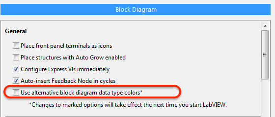
Use the colors of the alternative type block diagram data?
Options window 2016 LabVIEW to offer this new option:
The help file, however, is not the document, and I have been unable to find anywhere in the options window where the data type of alternative block diagram colors could be defined.
Any explanation would be welcome.
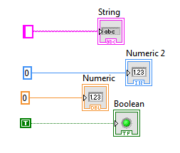
I drop everything possible, but decimal color seems to be certainly changed, and it seems that the real colors have changed, too. I'm color blind, so am not sure if the other fundamentals have changed.
Option:
Option ON:
-
LabVIEW block diagram icons became invisible
I'm a bit of a loss here.
I worked on a fairly large vi of higher level for a while when suddenly several vi system developed display problems. In particular, all the screws of the FPGA module no longer appear on the block diagram. They are there, because I can move the properties and thread them, but they are invisible. Even if I add a new menu, it is invisible. Is the same for the control on the structure of timed loop block. The loop is visible, but the controls are not.
I have attached a picture of a part of the vi that shows what should be a 'open FPGA reference' and a timed loop. As you can see, the wires are connected and it compiles and works very well, but there is nothing on the screen
It is specific to this vi. If I create a new vi and add the same vi they look very well. As far as I know, I did not change to any display settings.
Any suggestions?
Hi Nathan,
You should be able to get a global position by moving one of the scroll bars. When you click or drag the scroll bar a small box should appear (right of the cleaning if the BD is enlarged or below the bar of horizontal scrolling if the BD is is not maximized) giving the global coordinates. If you find that you are outside about 15000 pixels (I don't know if it is a hard cut) are trying to move close to the origin.
You should not recreate anything. Actuall you can find the line where the icons become visible. In a quick test here he looked about 15000 pixels.
-
When I start my VI, a traditional State Machine, I can't use the buttons on the block diagram toolbar, or probe the block diagram. Nothing on the block diagram is accessible, so I opened each State to a separate VI to see if the problem of monitoring, but he goes. This issue seems to happen only with this particular VI, but I have no idea how to solve it. I am running 8.5. Thank you.
Seems that my FP was not modal by default, which caused all my problems. Thank you very much to those who have tried to help me.
-
block diagram control label display
I hope this has an easy solution.
I got code that has different formats for the control labels as they are posted on the block diagram.
Some have rectangles around the label, others do not.
I'm sure there's a simple (albeit tedious) way to make them all the same.
I realize that this is only cosmetic, but I prefer to code to be consistent.
I really don't like that as they are (although the new controls have rectangles, rectangles is probably better).
Does anyone know how to set this property?
Also, why would a view chosen on the other. I guess it's just personal preference.
Thank you
I was in the same situation. I prefer the no border around the labels. I think the 8.5 they've added another property in the menu options, so you can choose whether you want the border. The property is 'Use transparent name tags' on the block diagram tab. To change existing labels, you can use the brush with T selected for color (if you don't want any border look).
-
apparently random node placement on block diagram
When I create an indicator on the front panel, the block diagram node present in a seemingly random place. Sometimes it becomes hidden. The reverse happens when I create a node on the block diagram. The front object placement seems random.
Is there a way to get a container where all things will appear in this box? Can I predict where something might appear?
Carmen92126 wrote:
Is there a way to get a container where all things will appear in this box? Can I predict where something might appear?
No and no. However if you double-click on the new indicator, the terminal is highlighted. (and vice versa)
-
How to generate color on the block diagram box?
v: * {behavior:url(#default#VML) ;} O'Bryan: * {behavior:url(#default#VML) ;} w\: * {behavior:url(#default#VML) ;} .shape {behavior:url(#default#VML) ;}}}} Normal 0 false false false MicrosoftInternetExplorer4 / * Style Definitions * / table. MsoNormalTable {mso-style-name: "Table Normal" "; mso-knew-rowband-size: 0; mso-knew-colband-size: 0; mso-style - noshow:yes; mso-style-parent:" ";" mso-padding-alt: 0 to 5.4pt 0 to 5.4pt; mso-para-margin: 0; mso-para-margin-bottom: .0001pt; mso-pagination: widow-orphan; do-size: 10.0pt; do-family: "Times New Roman"; mso-ansi-language: #0400; mso-fareast-language: #0400; mso-bidi-language: #0400 ;} "}
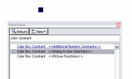
I found the code snippet below into an example, but I can't recreate the color box on the block diagram using LV 8.6. I can generate a color of the front box and then change to a constant on the block diagram, but I wouldn't be able to insert a color area directly from one of the palettes on the block diagram?
Thanks in advance.

jjgors wrote:
The color box constant is in the palette "graphics and sound-> photo functions.and much more...
-
Constant error cluster appears different in two places on a block diagram
I am a newbie to LabVIEW. I took Core 1 and 2 and Vision and I did not com on this before.
The right image is of course a constant of cluster of error used in the block diagram to create a cluster of error and it lead to an error on the terminal. As far as I can tell the left image is the same thing, but why is it different? The causes of different appearance raises a concern that there is a difference in behavior that I don't understand. LabVIEW help season both are constants for error. When I create a new constant of error, it always appear as the image on the right above. I was not able to create something similar to the image on the left.
Could someone please confirm what the image on the left on a blck diagram?
Thank you
Bill
The left image is a mistake of cluster control. He has a presence on front panel and can be set via the front panel or by a property node or a local variable. The image on the right is a cluster of error constant. It is a static value.
Maybe you are looking for
-
Restore the default message window
I accidentally resized my window Messages and I would like to reset to the default.
-
Previously available to Apple Watch case-band associations
Hello world I bought a Apple Watch of a webshop of part 3; It will be delivered to me on Sunday. The description says "42mm stainless steel with loop Milanese space black." After a while, I thought I would ask them better on the color of the "Milanes
-
Alert on said Safari that I downloaded a virus.
I have an IMac. Alert on said Safari that I downloaded a virus. MacCleaner came and I sailed through it, thinking it was an Apple product. When he wanted to enter my HD, I decided to ask a few questions. It is said that it will remove the "proble
-
After I reply to an email sent to me with an attachment, it goes to my sent folder, but their fixing transfers not on. How can I correct this situation?First time I'm doing this. I hope I am doing this correctly. forever39