apparently random node placement on block diagram
When I create an indicator on the front panel, the block diagram node present in a seemingly random place. Sometimes it becomes hidden. The reverse happens when I create a node on the block diagram. The front object placement seems random.
Is there a way to get a container where all things will appear in this box? Can I predict where something might appear?
Carmen92126 wrote:
Is there a way to get a container where all things will appear in this box? Can I predict where something might appear?
No and no. However if you double-click on the new indicator, the terminal is highlighted. (and vice versa)
Tags: NI Software
Similar Questions
-
Impossible to select and place the Instrument Driver VI icons on the block diagram
I am trying to automate some of the RF measurements using a Rohde and Schwarz Spectrum Analyzer. I downloaded the Rohde and Schwarz spectrum analyzer pilot named 'rsspecan' version 2.6.1 for Labview on Rohde and Schwarz site to use in my version of the software labview 7.1.
I copied the files in the appropriate folders in the Labview software on the C drive files. I am able to access those files through the functions---> Instrument I / O---> range of Driver of instruments in the Labview diagram, but when I select the VI icon that I want to put, I am unable to place it on the block diagram. Instead of hovering under the cursor by clicking on the VI icon, by clicking on the icon of the VI has no answer whatsoever.
Any help would be greatly appreciated.
Thank you
Thank you very much for the help.
So, is there a way to get the above mentioned pilot online Spectrum Analyzer, which will be also compatible with LabVIEW 7.1, so that I don't have to go through the conversion of version Board?
Thanks again,
Vivek
-
Hidden nodes and elements of block diagram
Hi all
I have this bizarre situation where having a terribly huge program, strange things happening. The main loop which is a massive, while the loop has been resized a few times in the past and now, the conditional element "stop to true.
the while loop is nowhere to be found but hidden away. All I can see are the dotted lines that connects the stop button to it. Extend the while loop to reach it seems to do nothing as long as it continues to be somewhere there. the while loop seems to be already reached their limit and cannot be expanded more. I tried the block diagram cleanup but its useless because it is another problem in the huge program, it does not cleaning for a reason any and she would have uncovered more problems. If anyone has an idea out there, please let me know. Thank you!
Another way to get a tune-up of hidden node is executed Analizer VI and the report will have a list of hidden objects... Just double-click the warning and the node will focus! then use the arrow keys to bring it back in the display.
-
place an image on the block diagram
Is there an easy way to place an image on the block diagram?
To clarify, I would like one simple to paste a bmp or jpeg or png or other means on my block diagram to document the block diagram for future programmers.
The way I currently accompish this is to create a constant of the photo on the diagram and running a vi separate to load an image in a window of the image, then using copy / paste to get the image in the photo correspondent in my block diagram.
There's a way more simple, right?
-
Constant error cluster appears different in two places on a block diagram
I am a newbie to LabVIEW. I took Core 1 and 2 and Vision and I did not com on this before.
The right image is of course a constant of cluster of error used in the block diagram to create a cluster of error and it lead to an error on the terminal. As far as I can tell the left image is the same thing, but why is it different? The causes of different appearance raises a concern that there is a difference in behavior that I don't understand. LabVIEW help season both are constants for error. When I create a new constant of error, it always appear as the image on the right above. I was not able to create something similar to the image on the left.
Could someone please confirm what the image on the left on a blck diagram?
Thank you
Bill
The left image is a mistake of cluster control. He has a presence on front panel and can be set via the front panel or by a property node or a local variable. The image on the right is a cluster of error constant. It is a static value.
-
LabVIEW: Null window... stopped to stranger on the block diagram
Hello
I have a pretty important program that has been written in Labview 6.0. Recently, we have upgraded to Labview 9.0 and this program has been exported to an executable file with the new version.
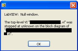
When you run the executable file, I sometimes have the following error as seemingly random places. I was not able to crash when not to use the executable file. LabVIEW: Window zero. The first level VI ".vi" stopped to stranger on the block diagram of ".vi".
I apologize for having empty on the names of vi, but I can't give names of vi, say what is the software or code. I can tell it uses NI USB-6212 IO cards, interfaces with the instruments of Rhode and Swartz and uses a lot of file i/o.
I was hoping someone could give me a hint on how to debug such a mistake. I noticed that when this error occurs, the memory usage almost doubles.
Thank you
James
-
What this block diagram?
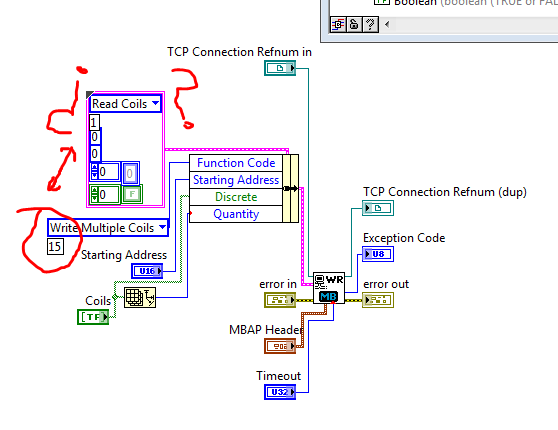
Match a VI Modbus Library. But I have because if the block is configured to write multiple coils in the coils because reading is set to 1?
All this work?
Sorry if the question is a beginner.
In this block diagram, 'Coils Read' and 'Write multiple coils' are enumerated values (or possibly ringtones of appeal, which is not serious for the purpose of this explanation). Enumerations assign names to numbers, to make them easier to read. The coils Read command is set to 1, the command to write multiple coils has a value of 15. You don't need to worry about this number, however, because the enumeration takes care of it for you.
The constant cluster containing coils of reading is there just to provide the correct data type (a cluster with the right items). Almost all the elements of the latter shall be replaced by the values of wired in the Bundle to node Name. For example, the value of reading coils is there as a placeholder for any function Code. the actual Code of the function is defined by plugging write multiple coils in Bundle by name.
-
Reduce clutter in the control on my block diagram reference...
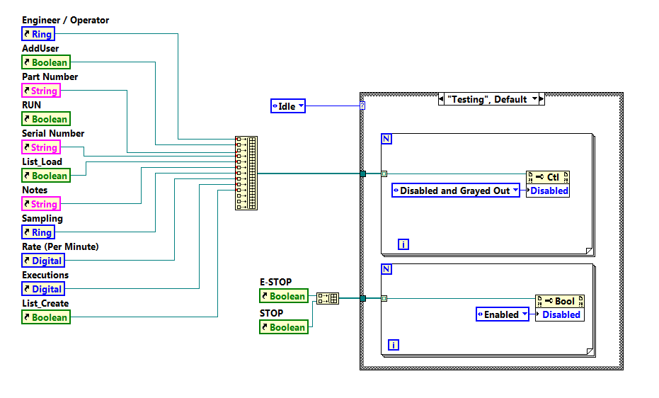
Is it possible to reduce the amount of clutter on my block diagram when needing to enable and disable controls so that the tests are running? I know that I can place the instruction box in a Subvi, but I'm looking for the best method recommended to reduce clutter when listing references. Using LabVIEW 2015.
Here is a small example of what I speak, there will be only for references to be added as the devlops of VI.
Thank you
Kellen
rkmadse wrote:
When you say I can clustor FP, say things that I did, and I have a group of controls such as those below in a clustor. I still have to generate reference constants, which are then placed in clustors. If I want to disable I would have then to consolidate each reference in the clustor, then ungroup and disable each control individually. I bet I'm really missing the point here and I'd love more explanation.
Thank you
Kellen
My main problem is not being able to place real dangerous in a Clustor.
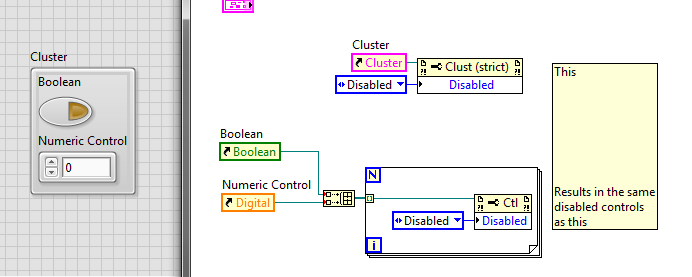
You think about transportation, when I talk about the horse. Your façade elements can be in a cluster, and then you can use the reference to the pole to disable all. See:
You will get a façade looking slightly different between the two options if you use disabled and Grayed out because when you grey on the whole cluster, the gray edges. When you gray unique items in the cluster, the cluster edges remain normal.
-
In LabVIEW 2010, I have a Def Type control i.e. a Cluster with several other controls within the Cluster. Apparently, the references to the controls in the block diagram are based on the order that the controls have been added to the Type definition command. The side effect of this is that if a control is removed from the command of Type definition, many of the done Variable reference in the block diagram or now either broken, or worse still, refer to wrong control in the Type definition. These problems are quite difficult to find and fix.
Comment: If you create a control of Type definition and make a Cluster. Now add any controls to the Cluster in an order, let's say A, B, C, D. Their types does not matter. Now use the Type definition in one or more controls on the front panel. In the block mark references to controls inside the Type Def would control on FP. Now return to the Type definition and remove the command B of the definition of Type. Now, lots of errors appear. Broken links. But worse still, you see old references to B that now refer to C and old references to C are now referring to the old references to D and D are removed altogether, etc.. This side effect is much more errors, broken links and misreferences than expected otherwise.
How add and remove controls anywhere in a Cluster in a Type definition, at will, without creating a whole bunch of errors in program, broken links and misreferences for controls in the Type definition that have not changed?
-
What is the best way to keep the block diagram / cleaning of façade?
Hello
I'm relatively new to Labview so I'm not able to say if I'm overloading my programs or make my too crowded block diagram. I was wondering if there was some ways to tell if I can simplify my programming just by looking (perhaps only experience contributes to these things)?
I enclose my VI here. Currently, she is able to monitor the voltage and current of two engines. On the screen, you can see an indicator with the voltage and current values and there are cards that can display signals of different engines with a menu drop-down.
The façade is pretty clean, in my opinion of novice, but the block schema seems messy to me, just at the first glance. I foresee a problem occurring in the future however. In the future, I will have the VI to monitor 50 engines globally. All of the programming will be the same as the one I have now, but it will have 50 indicators and unfortunately 50 times just about everything. I would like to avoid this, but I don't know how I did.
I use a USB-6009. I use its four differential inputs to monitor the voltage and current of the two engines. In the future, I will get more units DAQ (25 in total because 2 motors can be monitored for each data acquisition). The new Renault will help will help with more resource space, but I think things complicate with the added option of 24 more Assistants of data acquisition (as used in my code).
Thanks for any help you might be able to provide!
Usually, it is above all the experience that will teach you the best methods for making your code to do pretty. I don't know anyone who is proud of his first application of claws. There are some resources out there to help with best practices, as that group on ni.com, but you will learn most of your own development.
Your façade is superb. FPs in general really are to you. You can do it as ugly or pretty as you want. When you have a few controls in duplicate and the Group of indicators, you should use clusters and berries to simplify. You can use a bit of cleanup in this regard, but not much. In addition, I personally hate read red text unless it is a warning any.
Your block diagram could use a little cleaning in a sense of modularity. You have a lot of repeated code, which you might consolidate in to a Subvi, which is used in multiple locations, or in a loop For. A general rule is to keep your block diagram within a single monitor. You should not scroll. Your application is quite simple, so it is difficult to BUMBLE

Here are a few details on your block diagram:
- Click with the right button on your devices on the block diagram and uncheck the "display as icon". You are welcome.
- Operations on each waveform "(x*2-4)" / 16 in double ": create a Subvi and/or run the waveforms through a loop."
- You do a lot of 2-element arrays and then indexing. Just replace the ones that have a Select node based on digital.
- All your code runs every time, including the knots of your property at the bottom, which is not necessary. As you learn LabVIEW architectures, you will learn how to get around this with the initialization and the output of code, but for now, you should put a case around those structure for only when the engine numbers change.
- I don't know how you're timing your main loop, but you should put a delay in there because you don't need the DAQmx node shoot as fast as your CPU will allow.
There are videos of intro free that you can watch to learn what OR think in terms of coding and teach you some of the basic features and such. Here's a three-hour course, and here's a six-hour course.
-
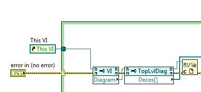
VI of script to read comments of block diagram
Hi people,
I have a small project to attempt to harvest comments in the block diagram, perhaps the help of scripts of VI. So, for example, when I'm checking #ToDo comments, I can get a list of the VI appearing in the #tag and collect the text. I think I found the method to get the comment, but I don't know how to recover the text in the comment. Here is a picture of how to get to observation in the block diagram (just using this as one small example VI)
Thanks for your help!
Rik
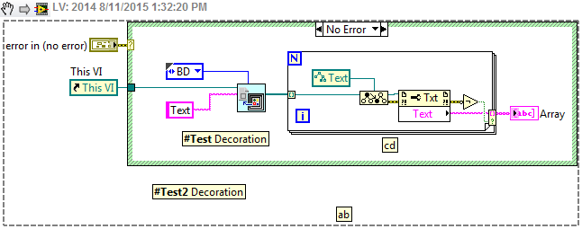
James.Morris wrote:
Here's what you want. It is worth noting that the current code only outputs the comment outside the structure of the case because you will need to dive into the structure for what anyone inside.
Yes this will cross all GObjects, but I'm sure there's a bookmark API Manager that will return comments bookmark if this is what you are looking for.
EDIT: Okay, there's an invoke node returns info bookmark on a VI but the VI reference may not be running.
-
Is there a way to tell if the block diagram is open when a VI? I have a Subvi, which is defined in modal when it is opened. When troubleshooting, if I run my application, but forget to disable modal for the Subvi forcing the system to lock upward.
It would be nice if I could set the property of the VI not be modal if the schema has been opened.
Any suggestions?
I would try to do several things:
1) go to the properties of the VI > appearance of window and click on the Customize button. From there, uncheck the box for "see the front when it is called.
(2) when the VI starts, read the 'Front Panel Window.State' VI property - this will tell you if the window is already open, (IE, if the window is open, the State of the window will be 'standard', "Increased" or "Reduced"). Note: This is the visibility of the front, not the block diagram
(3A) if the VI is not already open, set the 'Front Panel Window.Behaviour' property to modal and then open the front panel by using the node to invoke VI of "Front Panel.Open". It's basically imitating the behavior you describe this moment.
3 (b) if the VI is already open, set the property to the default or floating behavior to allow you to click other windows.
(4) when it is finished, if the VI is not already open, close it manually using the Panel.Close before invoking node (if it was already open, leave it open)
I've attached a screenshot of that sort of thing. I hope this helps.
Shaun
-
Programaticaly inserting block block diagram.
Hello to all 2!
I wonder if there is a way to programaticaly insert a new block in an existing diagram.
Take a look at the attached vi to see what I mean.
So... When I click on an image of the corresponding function is inserted in the block diagram, having as inputs the two controls.
Is there a way to do this or is this just wishful thinking?
 )
)Thank you very much!
It is possible to programatically manipulate the block scheme by obtaining a reference to it and operating on it with the use of the property and call the nodes. It's scripts of VI. You can write code that uses scripts in LabVIEW 7.1, but it can be imported in more recent versions of LabVIEW. This function is not supported by National Instruments. Being that it is not supported, I would not recommend research inside if you develop a code for a customer.
This should help you get started:
http://forums.lavag.org/VI-scripting-Readme-first-t1207.html
http://forums.lavag.org/LabVIEW-VI-scripting-F29.html&s=3fea8247be8d214406abf99a30e64e94 is a forum where you can ask on the scripts, being that it's about undocumented.
Welcome to the dark side, good luck in your journey and watch the rusty nails that you rummage through the attic of NOR. (lol sry, cheesy feeling on my lucnh break)
-
Is any way to put a VI that I placed on a palette in the menu functions to create a copy of it self when I place it on the block diagram?
My example is as follows. I create a palette for a messaging configuration. The 'send message', 'message' and so forth will work normally with just called when necessary. But 'Create queues messge' must be specific for each instance, because I'm going to create a different number of queues each time I use it. (See system messages in queue OR for the "Continous Measument and Logging" model).
So every time I drag and drop that VI (Create message Queues) in the palette, I want that it ask me where I want to save the VI.
Is this possible?
See you soon
Henrik
There is always the file-> new... that opens a new window. You can have your models in this window by putting them somewhere (I can't remember where at the moment).
-
exec Subvi system. Cannot access the positioning block diagram
OK I'm back!
My first question is that for some reason any I can reach is no longer here the files for you all to see...

Second and more to the point, how can I know the exec.vi for open system where I want it too when the block schema access is password protected and I can't seem to make the nodes property for the vi either.
I use this vi to call the OSK (on screen keyboard) for touchscreen.
I have an example to show, but see number one...
It seems to me that you want to position the osk and that means access to the block diagram is irrelevant.
To position the program that you are a beginner, try this.
Maybe you are looking for
-
Re: Networking on Satellite A105
I have a Satellite A105 that I m trying to fix for a friend. It is currently not possible to use a network connection, I tried Windows and Linux and I ve replaced the wireless card.None have worked. Any ideas?
-
Can I use product for Satellite P300 on Satellite P100 recovery?
I lost the product recovery disc for my P100, but I have the discs for P30 and P300, which are all two windows XP. My P100 which uses my husband became so slow that I feel I have to recharge it. But when I tried to start holding 0, F8 and F12 (one of
-
my friend has the above configuration as shown. has changed some time ago to setting and has the current problem: documents are printed in color if he wants, moroccoin only small-scale BW JPG, tiff and others. the printer, grayscale printing is not l
-
TouchSmart tx2-1370us: laptop found in the trash
Yes, found this laptop in the trash. Replace the power adapter, it turns very well. Problem is that the hard drive is a paperweight now. How to make a recovery disk? I get no option to order one of HP in the downloads section. Thanks for any help.
-
A few songs in MP3 format plays on the rocket but play fine when I use the computer media player
I have a 8 GB Fuze with an 8GB expansion card and I downloaded the latest firmware (I think it is 2.3 something), but sometimes when I play a few Mp3s just make a high-pitched sound weird, fast and then move on to the next. When I have the "rocket" p