Nor-Daq 6251 set hour/time between samples
I'm trying to calculate the expected error for an experience that I do and I don't know if I've done enough to determine the 'break-in' or the time between samples.
We use 8 differential channels to the maximum sampling frequency, the card can do (1.25. MECH / s). If I understand correctly, the minimum time between each sample must be 1 / 1.25 M, or 800 nanoseconds, such as the maximum time between sampling channel 1 and channel 16 would order 12uS (800nS * 15). If the expected voltage settings are the same for each channel (+/-10v), would a break-in? If so, how long?
In addition, if a channel is upward, and its tensions have an offset, DC on 5 or 6 volts, should that severely increase break-in if all other channels averaged about +/-1v?
I'm sorry for the basic question, I couldn't find a straight answer in the documentation.
Hi LSUgrad85,
When looking for specific device information detailed Specifications for this device will usually provide the details you are looking for. After the back if you have questions about the information in the detailed specifications.
I hope this helps!
Kind regards
Tags: NI Software
Similar Questions
-
Neither daq 6009 - delay in time between the measures
Hi all
My first post
 I have a small question about the acquisition of data with the NOR-DAQ 6009, where I try to get one or more number of samples per minute. Let's say I want to wait for some time before taking a measurement. I don't know how to do this. I tried to figure it out by myself, but because I am completely new to LabView and I come from the OR-6009, I was wondering if someone can help me here.
If this is useful, I enclose the .vi.
Please let me know if you need more info.
Thanks in advance.
You would get the timestamp before the average like I said or just call to get Date/time according to the seconds. Example below. You can recreate a waveform data type or do whatever you want with the timestamp and the average.

-
How to set the time between slides in a slideshow (iPhoto, el capitan)
How to set the time to say - 5 seconds or 20 seconds - between slide show photos in iPhoto. I use el capitan.
See the Settings button at the bottom right of the toolbar (at the bottom of the slide show). Click on it and you have a small window with two tabes, refers to all the slides, the other to the selected slide. You can make your choice
-
How to set the time between workstations and Server 2008 R2
Hello world
I have problem with my Server 2008 R2
all the workstations on my company doesn't synchronize the time on the domain controller
I tried many ways to set up automatic synchronization via command prompt (Net time) and its does not work
Please help me configure the time between the DC and the workstations
Thank you
Windows Server forums:
http://social.technet.Microsoft.com/forums/en-us/category/WindowsServer/ -
Hanging tool select disabled but time always snaps between sampling Points
Hello
In the Waveform Editor, when I Zoom in directly on the waveform, the points become visible. I have 3 Q: -.
- What are these points
- They can be changed
- How can I select (with the Selection tool) anywhere on the waveform?
- I deselected waspish and yet I am with zoom basically I can only place the time tool (TST) between the points visible, i.e. hearing snaps TST so I can not place exactly there where I want
Thank you!
The points show the individual samples in your digital recording.
Jump to your last question, you cannot place the time between samples picker because samples are smaller individual representations of the original audio. the lines between the samples are an artificial creation, making a waveform of samples. There is an excellent video showing how digital audio works - I recommend highly a cup of coffee and a viewing: D/A and A/D | Digital Show and Tell (Monty Montgomery @ xiph.org) - YouTube
Spacing of samples is determined by the sample selected speed which, in turn, is controlled by the clock system (Word clock).
As for the editing... not really. Older versions of hearing used to allow you to enter a sample and move it upwards or downwards, but the results could be unpredictable - under Nyquist theory there is only one waveform (i.e. one correct) which corresponds to the sequence of individual samples. Changing a single sample (or even two or three) can force the system that analyzes samples and draws the analog waveform by doing a few calculations confusing, incorrect. If you watch the video above and "read between the lines" you can see why that would be.
-
Problem setting Legacy DAQ board using NOR-DAQ 6.1 for Labview
I know that the Board of Directors is an old legacy product not supported by NEITHER, however for a low-budget project, I have 3 of these AT-MIO-16 x cards and the need to use them.
I know I got this job in the past not distant os, however, for the life of me can't get things sorted and work.
You use a NT box, in which this configuration used to work... uninstalled and started fees for other reasons, and I can not get the NOR-DAQ 6.1 to support LAbview 6.1 or 7.1.
Of course, I understand the OR-DAQ 6.1 should be used for Labview 5 and older, but also know this has been successfully done in the past.
I downloaded all knowledge base articles dozed or both support and remember to use successfully the last time that I set up so I know not somehow it works.
My configuration is: AT-MIO-16 X to the bus combo board (called work)
NT PC
LabVIEW 6.1 or 7.1
NOR-DAQ 6.1 is the most recent to support this card.
However, it will not install its support to its latest versions of Labview and I get errors, crashing, or missing files, when I followed various circumvention of knowledge base solutions.
I was hoping that someone has a documentation somewhere how to handle this, because it really is a matrix of spaghetti.
I can get NOR-DAQ support files installed, and Configuration Manager works well, finds the map and allows its parameters to be defined.
But when I load the DAQ vi of any type, Labview accidents and the wizard of data acquisition channel does not work at all (no error).
Thank you
Yes, the installation program from the folder of disks for NOR-DAQ 6.1 on the ftp site has worked well.
Workaround. Thank you
-
How to set the time difference between each data when using keithley 2400 scanning
Hello friends,
I use scanning Keithley vi the extent of SCANNING and acquire vi. I want to measure the voltage for each step and a pause between each two data, so I need a delay between each I step.
I'm a starter to use Labview, thank you very much for your answers.
Perry
As Dennis says, if you use the built-in scan function, you will need to consult the manual. See Section 10-16 (this is page 10 of article 16, only paragraphs not but 10, 16) for the manual Keithley 2400.
The Keithley 24xx series has a speed of measurement in units called PLC (Power Line Cycles). The default speed is 1PLC, which means a measure is taken with each cycle of line 1 power supply or 1/60th of a second (16.67ms). 24XX can range from 0.01 PLC (all 0.16ms) 10 PLC (all 166.6ms). The faster you measure, the less accuracy you get.
To programmatically set this value, the command is
 ENSe:CURRent:NPLCyclesENSe:VOLTage:NPLCycles
Depending on what you are sensing and where
is the number of controllers from 0.01 to 10. Another factor that will determine the time between data points is the cycle SDM. These are more complicated, look at your Keithley manual for more information. Look at article 6 and article 11 for more information.
Note:
PLC times are based on a cycle of 60 Hz US.
-
Cannot set the time zone of Moscow winter + 3 hours.
Cannot set the time zone of Moscow winter + 3 hours.
Set the time zone Minsk 3 after the GPS clock moves forward 1 hour, timezone is set back from Moscow + 4.
It is an error of your software when you are ready to address this issue.Automatic deactivation date & time(Settings>Date&Time...)
-
How to set the time of Capture from 05:30 to 05:45 hours?
Hello
Is it possible to set the time of Capture from 05:30 to 05:45 hours? These are Indian and Nepali zones. Change the Time\Shift of Capture by a defined number of hours (time zone setting) only allows adjustment in hours and not fractions of hours.
It will be great to have this one adds new versions of Lightroom as 05:30 and 05:45 are, as well as other more exotic combinations, valid time zones.
Kind regards
MV
Ian said, you can do so by using the option adjust Time Zone, but you CAN do it if you select all the images you want to adjust in the grid, make sure that the first of the series is the 'selected', then use the FIRST topic option 'Edit Capture time'... basically, you make the setting for the first image using a specific date/time then all the rest are adjusted by the same amount as the first.
-
Link of the website NOR to set sbRIO times
Hello
Can someone send me the link OR to set the sbRIO time settings. I have trouble setting the time recorded data (data connects to the memory of sbRIO) at the time of the PC. I even set the time accordingly to the MAX.
-kdm
Is there a battery for real-time clock your sbRIO?
Some of the advice sbRIO isn't (at a glance for a watch battery housing) and as such, you will need to create a daughter card from the connector CTMR to power battery otherwise the clock, that he will return to the power loss.
Normally, I think you get to the web configuration while putting the device IP address in the browser, but it depends on the configuration. You can also right click on it in the MAX configuration click on 'web '. You can also set the date and time on the device of programming using the screws AND Configuration System.
-
Measure the time between two digital pulse
Hello
For a non-critical calendar application, I need to measure the time interval between consecutive TTL pulses, ranging from the order of 0.5 s for a few seconds, with a low accuracy of +/-10-50ms. The interval being measured varies between the rising edge of the first pulse and the front of the next and so on.
I have several input lines I need to deal with. Because it's a critical machination low cost, I don't want to use digital counters for each line, so I work with an acquisition of data USB6008 and have connected the input rows TTL on the digital inputs of the device. Avoiding will be sufficient.
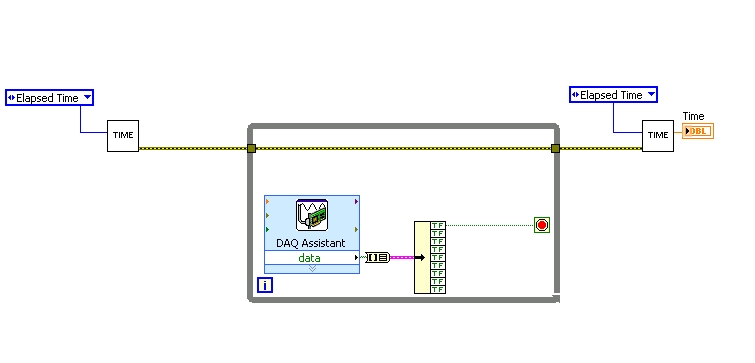
I found a good example of VI on discussion forums that does almost the same thing, only it uses instead of the DAQ Assistant user input. The VI works including the time the program going on in a while loop. I replaced with the DAQ Assistant output (a channel) user input in the hope that it is still work.
When I run the program in "run once" mode, it seems to work perfectly. However, in "continuous run" it measures only a very small interval, probably just the time between two samples. I think it has something to do with the help of a while loop in combination with the DAQ Assistant. Anyone who has any suggestions how to solve this problem?
Thank you!
OK... first of all, you should never use the button "run continuously. I wish that NEITHER would be to eliminate it, but told me that it is sometimes useful for debugging. If you want your program to run over and over again, use a while loop with a stop"" button.
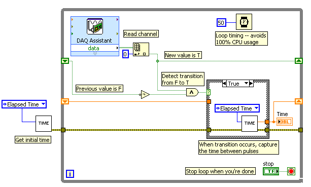
If I'm reading your code correctly, you make your initial moment, and then collect data from data acquisition. When one of the channels is "T", you stop your loop and the end time of capture. (By the way, why you convert your table to a cluster? Why not just index the appropriate channel in the table directly?)
Since you want to capture the time between two consecutive pulses, you need to know when a transition has occurred... i. e when your digital line went from F (no pulse) to T (pulse start). This will give you your forehead. Right now, all you're doing is looking for a value T - so you have no way of knowing if you are looking for to the previous impulse again, or a new impetus. You also burn 100% of your processor with the way you have your programme in place.
You need a small loop delay so that your VI is not 100% of your hogs CPU time. Given that you can live with an accuracy of 50msec, what I suggest that you use.
See attached picture for you give an idea of how to implement. He will probably need some refining operations, but it should point you in the right direction.
I hope this helps.
-
Verification of task names valid in the basis of NOR-DAQ
Hello
I have a question about the configuration of the tasks in the version of Base of NOR-DAQmx (I need basic because the application will need to be able to run on both Windows and Mac computers). The material is a box USB-6009, ordered through LabView. When you create a task inside LabView, is it possible to tell if the name you choose is already in use or not? Similarly, is it possible to get a list of and if all tasks are running?
The context is that I have a subroutine that made a brief burst of acquistion of analog input and then passes the result to the caller. I would like also to the subroutine to run standalone for different testing purposes. Normally, I would have the subroutine create and configure a task, the measure and then close the task. The problem is that the process of create/set up/start takes about 200-250 milliseconds (the measure itself is about 20 ms) that is long enough that I don't want to go through it whenever the subroutine is called from the top (I need to call this routine and do some other stuff a few times per second). So what I would is have the name of the task as a control on the subroutine, test that the value is a valid and if not valid only the initialization/etc. in the context of the subroutine, but if the subroutine has been passed a valid task from the top to skip a step all the time.
Looking through all of Base of NOR-DAQ functions, it doesn't seem to be something that allows me to do this kind of check with the exception of brute force to try to create a task and trapping so all errors that might be generated.
Suggestions (or ways) welcome.
Kelsey,
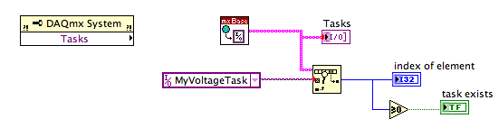
It seems that the property node is a component DAQmx, not a component DAQmx Base . I can't find any DAQmx Base property nodes.
dmsilev,
Try to replace the property node of the tasks with the DAQmx Base get tasks.vi. It is not in the DAQmx Base palette. It's a Subvi DAQmx Base create Task.vi. Caution: when you use a Subvi, which isn't on the pallets, know that they are generally not documented well and are subject to change in future versions of LV
If you weren't aware, DAQmx Base is written in LV and almost all the diagrams are not p [rotege so you can look inside and see how things are doing.
Lynn
-
I used a time capsule in my house. Now, I have another network put in place and would like to set my time for back ups and NOT as a WiFi capsule
If it is possible to turn off the WiFi on the Time Capsule, which only leaves you with the option to back up your Mac (s) using a wired Ethernet cable connection between the Mac (s) and the Time Capsule.
Are you OK with that?
-
How can I set a time string (start and end time) to tiara?
I wish to address a string of hour to 8 hours. Set the time of the departure of 16/03/2015 17:18:31 to 16/03 / 2015 09:18:31 (mm/dd/yyyy hh: mm :).) Is there an easy way (like the analysis or a script)?
Either use a script like this
Option Explicit
data. Root.Clear
protected chObj: set chObj = data.root.ChannelGroups.Add ('group'). Channels.Add ("time", DataTypeChnDate)
chObj.Values (1) = CDate ("16/03/2015 17:18:31")
Dim chNr: chNr = chObj.Properties ("number"). Valueprotected offsetInSeconds: offsetInSeconds = 8 * 60 * 60
Call ChnOffset (chNr, chNr, "free offset")or use
Analysis.Basic Mathematics.Offset Corrections
and add the offset in seconds as "add any compensation."
-
It seems that you can not set the time on a device sbRIO (9606) and have always the exact time when the card is powered after not being fed for a while. I have a product which will be independent (not connected to a network) when it is supplied by the customer. I would like to collect data in a datalog and would like to put a timestamp somewhere so that I can understand when these data were collected. If I can't get an exact date/time, then the next best solution would be to set up my datalogs so that I can at least understand the exact order in which they were collected. (I think I can understand it without much problem) Any suggestions as to best practices?
Hey John,
Without connected VBat time will not be preserved between periods of closure. Unfortunately for the 9605 and 9606 we have not a way to date the connector 9693 VBat.
How much sbRIOs you plan to deploy with your system? 9623 and 9626 have a compartment for the RTC. If you haven't bought your sbRIOs already you could focus on the options of the form always match.
If it is necessary to have retention time between stops, we would need to understand the extent of your application more.
Maybe you are looking for
-
Just hours since the update to 29.0.1, Firefox has crashed at least 3-times-extremely rare before
random-all crashes using Firefox 29.0.1.Sometimes the screen will blink first ALL black...Addons: NoScript AdBlock+ TabMixPlus HTTPS Everywhere
-
can I sync my mouse Apple to my Apple TV?
Can I sync my mouse Apple to my Apple TV?
-
HP laptop - 15-ac152sa (EN: HP - 15-ac152sa 15.6 "laptop screen replacement)
Hello I have a HP laptop ' HP - 15 - Ta152its 15.6 "and its LCD screen is damaged. I want to replace the display, please let me know the specific part for this model number.
-
C7100 printer: printer C7100 display
The screen of the printer's empty, with pale vertical patterns, like a line of letters is repeated from top down. Print worls OK, but I cannot read any message. Thank you for helping...
-
Satellite A100-599 - cannot install the driver for nVidia GeForce Go 7600 graphics card
Greetings to all! Try to install the driver for Nvidia GeForce Go 7600 after reinstallation of the entire system, but without success. Only safe mode is available after this pilot plant, tried with Windows XP, Vista and Windows 7 and with different d