of WPF XY scatter chart
I'm trying to display a WPF graph where each data point corresponds to a constant fractional delta along the asis x. E.. g. (0.15, 1), (0.30, 5), (0.45, 3.6),...
My best guess is that I want to draw an array of Points that contain values such as above because I do not understand how to inform the chart control that each value to plot represents a value of delta-X which is not 1 (e.g. 0.15).
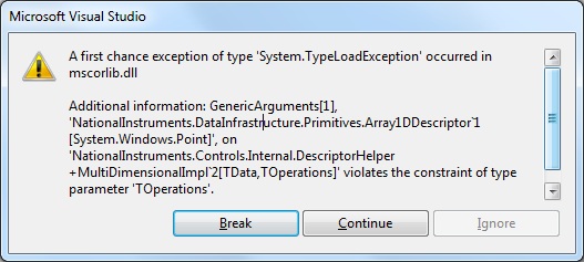
When I try to update the dependency property of the data source of the graph through data binding (for example to call the event handler property change with the name of the property of code-behind), I get the following exception:
I have sought examples of graphics 2D point clouds using the WPF chart without success control. Note that this is a different problem from that of several plots on the same graph display.
Thank you in advance for your help!
-Paul.
Currently, we have an example called 'XYPlotting' that shows dispersion of the data in the chart in WPF. You can find this with the WPF examples that have been installed with Measurement Studio.
Pointis the most common type that provides data from point clouds, although like other types ComplexDouble or ChartCollection would also work (see how: map and graphic topic for a list of all supported data types).
About the exception, this is the expected behavior during the initialization of a data type. Note that it is a "first chance exception", which means that this dialog box appears immediately when the exception is thrown, even if it is subsequently managed. If you continue execution, you will find that the exception is handled, and the graph shows data.
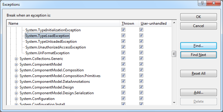
"Warnings of exception are controlled in Visual Studio through the Exceptions dialog box, accessible by the Debug" Exceptions... menu. "First chance" corresponds to the column up; Unmanaged user represents the exceptions that spread to your code:
To explain a bit more on the reason why the exception occurs: all the types supported by the chart controls is expandable and not fixed before hand. When a data type is encountered for the first time, we search to determine the best descriptor to use. The initial version of WPF controls, we chose to rely on the .NET, verification of the arguments type system generic, but since there is no method "such would be valid?" we must build the type and manage type load failures that occur. Because we cache the result, these exceptions do not often appear, but it is something we intend to improve in the future.
Tags: NI Software
Similar Questions
-
VS2012 problem of configuration and deployment with scatter chart
I've recently updated one of my programs of VS2008 to VS2012. I also had Measurement Studio 2009 and upgraded to 2013. Since Microsoft dropped its installation and deployment in VS2012, I'm looking to use Flexera Express to create an installer. My app contains a form that contains a scatterplot graph control that must be deployed on both Win7 and XP computers. I tried to force the compilation to .NET framework 4.5, but that only supports XP. I demoted the .NET framework down to 3.5. I noticed that I had to change the references OR whenever I changed the .NET framework. I only had references to the NationalInstruments.UI, NationalInstruments.UI.WindowsForms and NationalInstruments.Common. When I build the installation it requires me to explicitly declare the redistributable packages. So I chose the package OR Measurement Studio Windows Forms Support and automatically selects the load at the time of Design and common User Interface Support (dependencies I guess). But after I create this version of installation and install it on a system, I get the following message when you attempt to initialize the scatter chart control:
Could not load file or assembly 'NationalInstruments.UI, Version 8.9.35.246, culture = neutral, PublicKeyToken = 18cbae0f9955702a' or one of its dependencies. The system cannot find the specified file.
Y at - it a redistributable package I'm missing? I tried to add the base components for the execution of Measurement Studio, but get the same error.
I tried to use Wix, but ran out of patience, trying to figure out this one. Any help is greatly appreciated.
In general, when controls utilities deploying Measurement Studio you refer to this documentation for the required dependencies for the merge modules:
http://digital.NI.com/public.nsf/allkb/6677098983C36F9086256CFE007F457A?OpenDocument
-
Scatter chart: get the value of the label XYcursor
Measurement Studio Visual Studio Professional 2012 2013 using,.
On a scatter chart, it is possible to get the value of the actual label for a xycursor?
For example, my label displays a date-time on the X axis format, it looks like: [04: 35:49; 0,27101]
It is possible to get this value? For example, if I want to display in a TextBox?
I am able to get the xycursor. Which and xycursorYposition but not what I want.
Thanks for any help!

Here is a solution to my question:
{
Get xy cursor index of the point in plot
int index = xyCursor1.GetCurrentIndex ();Get values at that time (in the plot)
Double x;
Double y;
scatterGraph.Plots [0]. GetDataPoint (index, ByRef x, y);X value to the DateTime format & convert to the format of the time
DateTime t = (DateTime) NationalInstruments.DataConverter.Convert (x, typeof (DateTime));string time = t.ToString("hh:mm:ss");
}
It is also possible for which xycursor and convert it in the same way.
-
Scatter Chart with over 24 hours: confusing result
I have two columns of data. TIME is formatted as a date/time value with "Date: None, time: 19:07.» AVERAGE is formatted as a number. TIME contains values between 0:00 to 23:59. TIME is on the x-axis of my scatter graph, and the AVERAGE is on the y-axis.
When I create the graph XY scatter with these columns, the y-axis are mapping correctly, but axis x are not. Values of x-axis does not range from 0:00 to 23:59, but leave 08:05 on the left at 0:15 on the right. The values 0 and 08:05:15 not yet listed in my Chronicle of the TIME.
I suspect the formatting of date and time is the problem, but what is the solution (or work around)?
Thank you
view a sample of your table here for us to try would be helpful AND post a screenshot of what you have would also help you
-
Problem formatting Scatter the chart axis
All,
I'm trying to format axes on an XY scatter chart to display 0.0% vertically and horizontally to OBIEE 11.1.1.7.140527 0,0. I tried to set the format in the properties for chart point as well as the properties of column cloud (using these two formats appear in the list and the custom) and none of these approaches to return the correct format. The numbers keep appearing without formatting - that is, 90.0% appears to be 90 on the vertical axis. Also as a record, when I fly over the points of real data on the graph, the values are made 1 decimal place (so I know that they are not truncated), but the % does not appear after the vertical data point.
Does anyone else have this problem? If so, how to solve it?
Thanks in advance for your help.
Thanks for the photos (make it easier to visualize exactly what you are looking for).
The strange thing is that I'm trying now to build a chart like yours, and all defining the format of my vertical measurement in % place you in the y-axis % and keep the axis X for normal numeric values.
And I also found (mistakenly) where you can force the graph to display the % on axis Y.

There is a problem during the definition of % in the property "Abbreviations": your measurement is 0 = 0 and 1 = 100%.
If on the other side, that get in shape column or a percentage in the criteria tab measurement is 0 = 0%-100 = 100%.

I use exactly the same as you, OBIEE and defining the format of data in the criteria for my Chronicle of the axis tab of Y of the clouds of points automatically graph showed me the values of %.

There is an additional "detail": you lose % if you don't have a column in the 'Points' of the graph area, but you moved your column to "vary By color.
If bring you a column 'Points', the % will be on the Y axis, if you have a column only in the "color vary by" you lose %. You can get them back by using the properties of the axis, but don't forget to add a 100 to your measurement (and on the mouse on the screen data will be skewed as it will show % 0-1 instead of 0 to 100).
So I suggest to add a second instance of the same column that you use in "color vary by" and put in the area of 'Points '. % will return and you keep multiple colors. On screen, a mouse you have twice the same value on the screen, but it's probably smaller questions that you can live with if you get your good axis.

(PS: I hope that makes sense...)
-
find the distance between two major axis chart point cloud
Hello
I have a scatter chart. Its the y-axis AutoScale property is set to false. The major and minor axes are by default. Interval is set by default.
When draw the graph divisions displayed on the axis are defined according to the range provided. Sometimes, the interval between the major divisions, that is exactly what is defined in the Interval property and sometimes this isn't the same thing. As mentioned in the help the AutoScale property is set to true, sometimes by himself in order to avoid the congested labels.
What I find is the distance beween two major axes of the value axis, as the interval is not the same as set in the property.
Kindly let me know how to calculate the interval.
Kind regards
Nihad.
yAxis1.AutoSpacingMajorInterval
Replace yAxis1 by what is called your axis y on the scatter graph. If you don't know what it is, right click on the axis are the scatter graph, and then select Edit YAxes. Then a box will appear and you can see how it's called in the members section.
-
How can I set digitally Board chart origin?
How can I numerically define the origin of the work plan? The answer closest I can find online advises do to drag the origin of drag? It's irritating because I think most people use Illustrator because of its accuracy. Why on earth would I just arbitrarily plop my artboard original any old where it's only the basis of my project as a whole. Anyone know how to change digitally?
Let me give you an example of what I mean. I need set the origin of the artboard to the x axis of a scatter chart. The label of this axis is centered vertically, so the work plan must actually extend on 3pts below the x axis. Not only that, but I would go back on the artboard so that when I traced my points, I can simply enter the number, rather than do a lot of math to get it in the correct position. I realize in Illustrator, there's a chhart tool, but it will not work for this project.
Right now, I have a work plan which is 144pt high, the x axis is at 137.19pt and the bottom of the label for the x axis is 144 ft. I need 0 to 137.19 and reverse axis, as well as a period is positive.

Check this thread
JS - change CS5 origin of the ruler from the bottom / left (as CS4)
-
I am struggling to find how to use CSS to control the display of the data for a chart series.
I would like to control the line color, thickness, size of symbol, etc. for the two series I've posted.
When I look in the documentation for this type of functionality is mentioned for scatter charts:
You can change the styles of this symbol by defining alternative values for the property .default - color5.chart - symbol. Check out JavaFX CSS reference Guide for more information.
However, I don't seem to this information under the CSS reference.
How can I know what the css formatting would be for these parameters?Dig the caspian.css on the jar file. This file is rather well documented and contains all the current values for the CSS.
Karl
-
Why the cloud of points chart appears correctly?
Hello
I already posted a thread on point cloud graph , but no one (not even Macromedia!) was able to give me an answer and I tried on my own since then, but no result!
I am referring to WhazzInAName said on December 31, 2004 at 09:51 on Cfchart Livedocs
I only copied the XY scatter chart, pasted part in a CFM page and run it. It displays very well.
However, if I try to add a value greater than 1 for something particular chartdata, e... g.
< cfchartdata element = "25" value = "99.357" >
< cfchartdata element = "25" value = "90" >
< cfchartdata element = "25" value = "65" >
The graph shows only the value 65, but not the other 2!
I tried to draw the same values in an Excel chart and there is no problem at all. All points are displayed correctly!
What is the problem with the cfchart? Why it does not display the other 2 values?
Also, is not possible with the chart in Report Builder to specify sortxaxis = "yes" xaxistype = 'Ladder' yaxistype = "scale", or is it available somewhere?
Thank you and best regards,
Yogesh MahadnacProduct number 64506 is currently open for this problem. There is no indication of a problem at the moment.
Ted Zimmerman
-
Lopez Burk field (Double reciprocal plot)
Hi all
I'm doing a double reciprocal plot of my data of the enzyme. I don't know how to go from a basic scatter chart plot to a double reciprocal plot.
I got my macbook in 2014 and the software is: OS X 10.9.5 (13F1603)
Thank you much in advance.
Kind regards
J

Hello j,
Weber State University in Ogden, Utah, of a set of instruction has do a lot of Lopez Burk in MS Excel, that you can find here. Formulas to convert the data pairs are reversed, and the graph itself is a scatterplot with a linear trend line 'better to' added. Creating a table similar in number should be pretty simple by following the instructions in Excel.
Kind regards
Barry
-
How do a continuous line when it is absent from the data table?
I have a graph all the traces, but since there are blank cells on the table there are broken lines. I just need to know how to make them continuous.
This discussion should be under the numbers instead of MacBook Air? If so, remove needless zero data points or extrapolation can estimate points which are currently zero, as appropriate. If zero points are valid results, consider changing a scatter chart.
-
I was under the impression that if I specified a value xy on a XY scatter chart so that point would be displayed as a single dot. This doesn't seem to be the case. I tried creating a new route, but could not find the right method to achieve this. I'm new to nor ms and would be grateful for the help. I'm looking to produce a graph with x1y1 - x2y2 then a second draw, further on the same axis of x3y3-x4y4-x. I thought that I could do it on one single site, but appears not to be the case. I use vb in vs2010. any help greatly appreciated...
Hello
Is that what you are looking for?
Private Sub Button1_Click(ByVal sender As System.Object, ByVal e As System.EventArgs) Handles Button1.Click
Try
With ScatterPlot1
. LineStyle = NationalInstruments.UI.LineStyle.None
. PointStyle = NationalInstruments.UI.PointStyle.SolidDiamond
. PointColor = Color.LimeEnds with
With ScatterPlot2
. LineStyle = NationalInstruments.UI.LineStyle.None
. PointStyle = NationalInstruments.UI.PointStyle.SolidDiamond
. PointColor = Color.CyanEnds with
ScatterGraph1.XAxes.Item (0). Mode = AxisMode.Fixed
ScatterGraph1.XAxes.Item (0). Range = new range (0, 10)ScatterGraph1.YAxes.Item (0). Mode = AxisMode.Fixed
ScatterGraph1.YAxes.Item (0). Range = new range (0, 10)Dim xdata (1) As Double
Dim ydata (1) As DoubleXData (0) = 2
XData (1) = 6
ydata (0) = 2
ydata (1) = 6
ScatterPlot1.PlotXY (xdata, ydata)XData (0) = 3
XData (1) = 6
ydata (0) = 4
ydata (1) = 9ScatterPlot2.PlotXY (xdata, ydata)
Catch ex As Exception
End Try
End SubHope this helps
Curt
-
ScatterGraph does not manually change the axis to execution interval
I use the ScatterGraph and the WaveFormGraph in VS2010 Winforms application. I have the interaction mode axes set to EditRange. The WaveFormGraph command allows to edit the axis range by clicking on the end of the axis labels and modify them. ScatterGraph control is not even though the documentation I've read says it should. The mode of the axis does not seem be the question that I have changed between fixed and AutoScaleLoose (which is not the choice to have everything showing changing data, if you want your range entered manually to maintain). I tried a new project with a ScatterGraph control with the default settings and checked that it does not change the axis interval. Is there a way to change the settings to allow you to manually edit a ScatterGraph range in this way when running?
Thank you!
Hi Lybro,
You have activated the "EditRange" of the graphical object of point clouds InteractionMode? There are two places that the mode of interaction is defined, one for the axis and the other for the scatter chart, both must be enabled for writing at work. I just tested this with Measurement Studio 2013 and it works. Let me know if it helps.
Kind regards
Kevin
-
Show ToolTips and line graph point cloud where data extracted by SQL
I'm looking to create a scatter chart to display the results of a SQL query. The graphic appears as
I want to have the points to is joined by a line and - bubbles that appear when a single point are selected. My existing custom XML is displayed at the bottom of this post. I tried different formats between the < / tooltip_settings > tags, but nothing appears. Similarly, I tried different line format settings. Interestingly, if the string #DATA # is replaced with a block as...
< data >
< name of series = 'Dirty' type = 'Line' >
< y = '1.172' point x = "1063512000" / >
< y = '1.916' point x = "1095048000" / >
< point y = "5.57" x = "1126584000" / >
< point y = "15.0" x = "1158120000" / >
< point y = "144" x = "1189656000" / >
< / series >
< / data >
... then a line and bubbles appear. It seems that all that is in the #DATA block # is not enough to create a line, and ToolTips. The data is retrieved by a query that returns the 4 columns LINK, TAG, X_VALUE, Y_VALUE
Is there a way in which something can be configured for line and tool tips to appear?
Existing custom XML
<? XML version = "1.0" encoding = "UTF-8"? >
< anychart >
< Parameters >
< local >
< date_time_format >
< format > %u < / size >
< / date_time_format >
< / locale >
< / Parameter >
< graphics >
< graphic plot_type 'Scatter' = >
< data_plot_settings >
< line_series >
< tooltip_settings enabled = "True" >
< / tooltip_settings >
< / line_series >
< / data_plot_settings >
< chart_settings >
< title >
Scatter line < text > < / text >
< /title >
< axes >
< y_axis >
< title >
< text > County < / text >
< /title >
< scale type = "Linear" / >
<>labels
< format > {value %} {numDecimals:0} < / size >
< / Label >
< / y_axis >
< x_axis >
< scale type = 'DateTime' major_interval = '1' minor_interval = '3' major_interval_unit = 'Year' minor_interval_unit = 'Months' minimum_offset = '0' maximum_offset = '0' / >
<>labels
< format > {value %} {dateTimeFormat: % YYYY} < / size >
< / Label >
< title enabled = "true" >
< text > Date < / text >
< /title >
< / x_axis >
< / axis >
< / chart_settings >
#DATA #
< / chart >
< / charts >
< / anychart >
This is because the apex generates the series not as a type of line, but as a type of marker:
... You will need to provide the data yourself, in the format you want, that is to say a series of line type. You can't set it up.
-
I'm having some trouble of tootip. The scenario is that I'm back from the data of an EJB (that works). You're supposed to be stationary on a mark on a scatter chart, and it gives you some information about this brand. I can't make it work. Maybe I'm too simple on the way I coded it? In any case, here's my code:
The chart displays OK, but when I hover over one of the brands, it shows me nothing. I do something of wrong, but what?("array" comes from the EJB, and each entry in that array is another array) XYChart.Series<Number, Number> normalSeries = new XYChart.Series<>(); XYChart.Series<Number, Number> negativeOutlierSeries = new XYChart.Series<>(); XYChart.Series<Number, Number> positiveOutlierSeries = new XYChart.Series<>(); for (int i = 0; i < array.size(); i++) { ArrayList arr = (ArrayList) array.get(i); // intercept, slope XYChart.Data data = new XYChart.Data(arr.get(0), arr.get(1)); System.out.println("tooltip: " + arr.get(3)); // tooltip Tooltip.install(data.getNode(), new Tooltip(arr.get(3).toString())); // check outlier if (Integer.parseInt(arr.get(2).toString()) == 0) { normalSeries.getData().add(data); // if the outlier isn't zero, check slope } else if (Float.parseFloat(arr.get(1).toString()) < 0) { negativeOutlierSeries.getData().add(data); } else { positiveOutlierSeries.getData().add(data); } } sc.getData().addAll(normalSeries, negativeOutlierSeries, positiveOutlierSeries); sc.setLegendVisible(false);
Thank you!The other mechanism in this thread seems to work ok:
import java.util.Random; import javafx.application.Application; import javafx.beans.value.ChangeListener; import javafx.beans.value.ObservableValue; import javafx.scene.Node; import javafx.scene.Scene; import javafx.scene.chart.NumberAxis; import javafx.scene.chart.ScatterChart; import javafx.scene.control.Tooltip; import javafx.scene.layout.BorderPane; import javafx.stage.Stage; import static javafx.scene.chart.XYChart.*; public class ScatterChartTest extends Application { @Override public void start(Stage primaryStage) throws Exception { BorderPane root = new BorderPane(); NumberAxis xaxis = new NumberAxis(); NumberAxis yaxis = new NumberAxis(); ScatterChart() { @Override public void changed(ObservableValue observable, Node oldValue, Node newValue) { if (newValue != null) { Tooltip.install(newValue, new Tooltip(datum.getExtraValue().toString())); datum.nodeProperty().removeListener(this); } } }); } scatterPlot.getData().add(series); root.setCenter(scatterPlot); primaryStage.setScene(new Scene(root, 600, 600)); primaryStage.show(); } public static void main(String[] args) {launch(args);} }


Maybe you are looking for
-
Try to download Covenant eyes & firefox will not let it happen. Help, please.
A year ago, we downloaded the program from covenanteyes.com using Vista and Firefox. All went well for months.Since then, our laptop has crashed (unrelated reason). All lost.Started fresh with Windows 7. We want to install Covenant eyes on the new sy
-
I film not included with the download of El Capitan
I upgraded to El Capitan in 12/2015. I just realized that IMovie isn't the case to find. In research, it should be part of the built-in apps. The App Store wants $14.99 for app. Not sure why I should pay if she should have been included in the packag
-
Adobe Flash player is really necessary
I heard that Flash player is no longer necessary on a mac. I'm curious to know if this is true?
-
I have a screen which indicates the music with an image very dark of a girl, listening to music, but I can't go past this screen to my playlists. This just started happening in the last two days. Any suggestions?
-
My lifecam vx-800 works, but its too dark yesterday... all the settings are default... What is the problem there?