Oscilloscope for the acquisition of data from the usb-6009 or - example of temporal division for 5 seconds, 10 seconds
Hey Hey everyone
I was looking for an example for two-channel oscilloscope virtual using e/s all-in-one of the 14 bits of NI DAQ USB 6009. I tried to research for example BOF time division or s/div for 1 second, 5 seconds, 10 seconds. but was shocked to find that there is no reference for it. The range of oscilloscoper virtual
Minimum - 10 micro s / div maximum -10milli second div but there is no example for 1 second / div or 5 seconds / div... If anyone can guide me. I'm new to labview environment.
This is the oscilloscope two sample obtained from google search. is there material limitations. ?
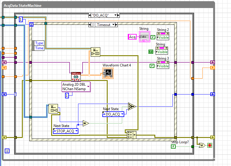
I'm working on continuous 4-channel data acquisition data acquisition using niusb 6009
The sampling frequency is sufficient for any desired s/div. The sample rate is 12 ksamples / s per channel, so if that meets the Nyquist criteria for the input signal, you can capture it. The number of samples has no effect on that with the exception of the amount of the signal you acquire. Your chart is not stable, if you do not trigger the acquisition. Even as real significance, therefore your emulation seems actually successful.
Tags: NI Hardware
Similar Questions
-
What is the MTBF for the USB-6009 case
What is the average time between failures (MTBF) for the USB-6009 case?
Hello
Unfortunately, there is no available for the USB-6009 case MTBF. In order to retrieve this information, there is a cost for our R & D department. If you need this number, please contact your local representative OR or open a service request to ni.com/ask.
I apologize for the inconvenience.
-
How to configure the PFI0 terminal on the USB-6009 case as came event counter
I'm watching the 8 inputs on the USB-6009 case and when fires Terminal PFI0 start saving the data.
Y at - it and why to read the 8 inputs while monitoring the PFI0 terminal? I appreciate any help!
Hi yacs1,
You can certainly do. I assume that you already have your 8 entries read correctly. Everything you have to do is now to put a statement button in your loop that is controlled by your pfi0 line. If this line is high, then save the data, if it's low, then only display data of your control. If you need help reading the pfi line, open finder example under help > find examples. Then go to the material input and output, reading Dig channel DAQmx, numerical measures. If you need help logging data, go in Fundamentals, file input and output, and then depending on what type of file you want to write to, find the appropriate example (IE write into text file).
Let us know if you need more assistance,
Ryan
Technical sales engineer
-
acquisition of data from the old Spectra via GPIB Analyzer
Hi, I got an old parser of Spectra (MS2601J, anritsu), I want to get through the GPIB measurement data. I downloaded the driver for MS2601B/K on the site, but it does not work. commands such as "INI" cannot be recognized. I tried the MAX for the finding aid. You can find it, but if I send the command ' * IDN?', no response will not returned. I checked the manual and sent the command "\r\n INI", there also was no answer. I'm new to labview and perhaps I wrong interpret these commands. Does anyone know the format of the MS2601 order and tell me how to get the data of the instrument by GPIB?
Any suggestion is welcome!
Hello brileo,
Normally, you can select the scale X of the chart with the mouse and right click to disable the Auto scale or to access the properties.
You can also type the range values you want directly on the displayed scale. For example, from 0,0 on the origin.
But the program of the driver you are using now, replaces the properties of theses (using nodes of property) with the "frequency of reading settings.vi' in the sequence"1"of the"Sweep"case before the display of the data.
Instead, you can try to use SPAN and signal search SCROLL buttons in the front of the user to select the instrument of the area to see the signal.
For the data to be save in a text file, I advise to use the available examples of LabVIEW.
You can find them with the HELP menu > find examples... and select in the viewfinder of sample OR:
Basic principles > Input and Output file > write the text file.vi dataThis example shows how to open or create a text file from a prompt to the user message and write the data to the file.
You can delete the simulation of data in the schema of loop and call a copy of this program in your pilot AW 2601 B/K Example.vi.
Do you want to insert the copy of the "Save Sub VI text" you have created in your diagram when it executes the case of' punch' and
executes the sequence 0 [0.2] to read the data of the spectrum of the output table.Hope, which resolves the orientation Data Analyzer. Ask again through the Discussion Forum for other questions.
Carl
-
Acquisition of data from multiple loops
Hello
I tried to adopt a program of data acquisition of multiple loops with control of queue, but it does not work as it should. (Or at least the way I think it should) Could you please help me it smooth? I have seen a few screws on the internet with the queue-control and tried their adoption.
My program should work this way: after you complete the settings, I begin the acquisition of data (an analog output and 2-4 analog inputs), but I only want to save the data acquired when I click on a registration button. (Then these data would go for further analysis). While doing the analysis, the acquisition may be suspended. However, when I click on record I would like to have a feature to instantly restart the recording and to ignore the previously recorded data.
MainProgram vi is the application itself, with some settings made by the event handlers (now only limited to a selection of signal file and the channel settings). Then the data acquisition can be started by clicking on the button start the Acq.
And these are my issues: first, sometimes the queue starts, sometimes is not (or at least it does not start the data acquisition). And the main point: I put the sampling frequency, but it is acquired at a slower pace of well (my signal has a delay of 4 seconds, but he needs at least 20 seconds before getting close to finishing). And the strangest: sometimes, especially after some time (about 1-2 min) it freezes and does nothing with the acquisition of data (yet labview seems sensitive, just my program blocks somewhere).
So now only controlled acquisition is in the problem and firstly I don't like on the transmission data for analysis and recording. (Which seems to be the smallest problem).
What I am doing wrong? Thanks for your help.
I join all the files. (MainProgram is the application itself, MY. SIGNAL is the signal I want to exit.) I use a USB-6211. (for physical work, home a simulated).
Not directly related to your mistakes but (and here I don't mean to take on you, but... With an alias as yours, I assume that you have some sense of humor)
Really? an event structure single image with only one case of timeout (value 1mSec) with a Dequeue inside element
 how do you code would work by simply removing the structure of the event entirely
-
Configuration of the digital output in the USB-6009
I have a card for the acquisition of data USB 6009. It seems that him when DAQ card is turned on, it is always default to digital output of 'High' or 'floating '. I want to default to 'low '. Is there some setting I want to 'program' the hardware DAQ to have all the outputs low when it is powered on the value? Right now I have manually enter MAX and adjust the level 'low '. Thank you very much for your help.
Sid05,
Yes, it's low of 820 ohms. Unfortunately, the way in which the system is built, it is the only choice you have without having to build external circuits such as SnowMule suggested.
AK2DM,
Thanks for pointing the USB-6000. Finally a real, if limited, the DAQ hardware. Nevermind, he was only 4 DIO lines.
Lynn
-
Output analog, the USB-6009 case - can I use DAQmxWriteAnalogScalarF64?
I just got a NI USB-6009 and I try to use the outputs analog simple.
I'm running on a Mac, so I'll try to use the API OR-DAQmx Base 3.2 C (downloaded from here: http://joule.ni.com/nidu/cds/view/p/id/1078/lang/en). This is the most recent version of NOR-DAQmxBase, I could find.
I try to do continuous analog output on the 6009, which does not have a built-in clock. I was hoping to do the sync software and just new output values when I want to.
I can't get an output of database to work. Other messages and the example of Windows files, (e.g., National Instruments/NOR-DAQmx Base/examples/ao/MultVoltUpates-SWTimed.c) it seems that the best thing to do would be to use the DAQmxWriteAnalogScalarF64 function.
However, this is not in the Mac version of the C API of NIDAQmxBase. There is actually an entry for this in the NIDAQmxBase.h file, but it is commented out. Anyone know why? Is it possible to use this function for the analog output on request on Mac?
Thank you.
Clement
I have NEITHER-DAQmx Base installed 3.2 on a 10.4.11 system. One of the examples files 'genVoltage.c' calls DAQmxBaseWriteAnalogF64. I was able to compile and run this example with a USB-6009.
The DAQmxBaseWriteAnalogF64 function would work for you?
My guess is that, since you can write a scalar value with DAQmxBaseWriteAnalogF64, DAQmxBaseWriteAnalogScalarF64 becomes superfluous. The example provided with the installation shows how to write a unique value (i.e. scalar.). I pasted the code of OR below.
int main (int argc, char * argv [])
{
Task settings
Int32 error = 0;
TaskHandle taskHandle = 0;
char errBuff [2048] = {'\0'};
Channel settings
Char [] = "Dev1/ao0" chan
float64 min = 0.0;
float64 max = 5.0;
Sync settings
uInt64 samplesPerChan = 1;
Writing data parameters
float64 data = 3.25;
pointsWritten of Int32;
float64 timeout = 10.0;
DAQmxErrChk (DAQmxBaseCreateTask("",&taskHandle));
DAQmxErrChk (DAQmxBaseCreateAOVoltageChan(taskHandle,chan,"",min,max,DAQmx_Val_Volts,));
DAQmxErrChk (DAQmxBaseStartTask (taskHandle));
DAQmxErrChk (DAQmxBaseWriteAnalogF64(taskHandle,samplesPerChan,0,timeout,DAQmx_Val_GroupByChannel,&data,&pointsWritten,));
Error:
If (DAQmxFailed (error))
DAQmxBaseGetExtendedErrorInfo (errBuff, 2048);
If (taskHandle! = 0) {}
DAQmxBaseStopTask (taskHandle);
DAQmxBaseClearTask (taskHandle);
}
If (DAQmxFailed (error))
printf ("error in DAQmxBase: %s\n",errBuff); ")
return 0;
}
Hope this helps!
-
How can I download data from key USB flash to a Windows 7 computer
I need to transfer some files from my PC to my PC Windows 7 Windows XP using a USB flash key. I've used Windows Easy Transfer to move my files without problem and some programs but did not download some files. I downloaded these files on a USB flash and I can access the files, as long as the stick is pluged. How can I download data from the USB flash on my Windows 7 computer
Hello
The following video may help:
http://www.YouTube.com/watch?v=hrMQh0Xkpvs
or this article:
http://www.swarthmore.edu/documents/administration/its/how%20To%20Use%20A%20USB%20Flash%20Drive.PDF
and here:
http://TECHTIPS.salon.com/use-USB-flash-drive-transfer-files-PC-Mac-2544.html
(Mac here can be a PC).
Good luck.
-
Is it possible to collect 16 channels of analog data using 2 USB-6009?
I got this error when you try to read voltages of 2 USB - 6009 s:
Error-201426: one or more devices do not support multi-equipment tasks.
John
Create a separate task for each device.
-
Acquisition of data from an external device that uses RS - 485
I am currently using a device cDAQ 9174. I'm trying to connect the cDAQ to an external source that communicates via a cable series RS-485. I spoke with several representatives of Lawbview and they told me that there is no direct way to talk on the chassis with the serial cable. I need to buy a USB-485 cable series and communicate in parallel in LabView. If I go directly through the cDAQ chassis, so why do I still need? And I'm lost as in how I communicate with an external source in Labview.
My second question.
I have a cRIO 9074. And, through a lot of research, I noticed that it seems much easier to use this device for this situation. My only problem is that I am new to LabVIEW and I think that working with the cRIO can be a little difficult for me at this stage. My question is, it would be easier to make the acquisition with the above configuration, or use the cRIO and spend a little extra time.
The application that I am trying to make is the following:
I have a RS-485 of the external source. Then, I want to broadcast the series of 2048 byte stream that is continuous in NEITHER and do review the serial data and assign a virtual indicator on a chart or display a message to tell me what will happen in the serial data stream.
cRIO is certainly more complicated to go only a USB-485 cable. cRIO is designed more for embedded applications, series No. You must also cDAQ in the equation. All you need is the following:
NEITHER USB - 485
http://sine.NI.com/NIPs/CDs/view/p/lang/en/NID/12845
Someone suggested a cDAQ to you for this application? cDAQ is a platform for flexible data acquisition for reading of the analog signals and digital bullies. If your data flow conforms to the RS-485 standard, you don't want cDAQ for this.
I have attached a sample program to help you get started. There are examples that are included when you install the NI-VISA driver that supports communication with LabVIEW series with LabVIEW. If you have installed NI-VISA it should appear on you NOR Finder example located in the main menu to help > examples find if you search for "serial".
-
Hello
I use 6009 USB to read the signals of the PMT and other equipment for experiments and I have a few questions:
1. is it possible to read a signal with DAQ assist? I looked around forums and have not seen any relevant element.
2. it is probably true, but I have not yet checked. Is it possible to read the two signals in the same loop (for example, AI0 & AI2 in awhile put in loop)?
I would be grateful if you point me to the right direction.
Thank you
A
P.S
I should probably mention that I want to read the signals with using DAQ hardware help because of the assumption that the DAQ Assistant is slower than a direct measure.
HEY Fan, Ravens
Nevermind, I figured it out... Well the first step of it at least :-).
Thank you once again,
A
-
temperature sensor with the acquisition of data usb-6009
Greeting
I want to use a sensor with usb-6009 to save the variation of body temperature about 15 minutes and then use these data in labview.
If you please you can advise me with the best low-cost use and the way/circuit sensor connect it to the usb-6009.
Hi ba7soun,
If you can use with USB-6009 LM35 depends on the range of output voltage of the sensor. I understand that it requires a 5V supply with respect to the ground, which you can provide to the USB-6009 (more than 200 my should not come from the USB-6009).
The maximum range of the USB-6009 is - 10V to + 10V, while the minimum range is - 1V to + 1V, also probably the output signal of the LM35 will be in this range. What you need to do is to compare the full range of the output signal with the range of the DAQ divided by 2exp (14) (because it is a 14 bit ADC) and ensure that the first is much more than the latter.
Kind regards
Condette Dhruv.
-
I use a custom scale and the DAQ assistant to acquire data from a USB DAQ device. How can I display voltage gross values at the same time?
Thank you
David
Do not use the ladder custom, but read the raw data using the daq assistant and adapts the data later. Or the scale of the data using the inverse of the custom scale.
-
Problem with the acquisition of data on XP Embedded
Hello
I'm using LabView 8.5, 8.7 DAQmx. My application is collection of data of NI USB-6009 14bits. I tried to create applications for tablet PC with installed Windows Xp Embedded. I created the installer on tablet with installed Windows 2000. I solved all the problems that occurs during installation. First version of the program have assistant DAQ in a main VI who collect and process the data. It worked properly on Xp Embedded. Second version was split into two of the Subvi. One is data collection and secondary processing. Each VI have own while loop. Both Subvi is placed in the large loop and they start at the same time. I am writing all the data to global variables. On PC with the windows application created 2000 worked properly. Error occurs when I moved it to Xp embedded. VI, which is the collection of data, the error see the 200361 code and text:
DAQmx reading (analog 1-d Wfm NChan NSamp) .vi:2
The task name: _unnamedTask<0>I know its something with the sampling and the clock, but I do not see where is the problem. In the main loop and two Subvi I 'wait until the next ms Multiple"block with a value of 200. DAQ Assistant were set as follows:
Price: 1000
Number of samples: 1000
Timeout (s): 10
Can you tell which can cause this error?
If you would like more information please write here.
Problem solved. There was connection between PC and USB-6009. Program works when I connect the USB-6009 housing directly to the PC. Previous connection was through usb hub.
Thanks anyway.
-
Why is the selection of the mode disabled in max for NIDAQ-USB-6009?
I try to use NOR-USB-6009 AO to generate the sinusoidal signal.
(1) I want to use MAX, but the selection of the mode and frequency are all disabled in the "Analog output" section
(2) I find a VB example to generate the sine wave, but I received an error message.
I want to know if the OR-6009 function support limited or not...?
The attachment includes the screenshot.
Thank you very much!
Kevin
Kevin,
Yes. Timed software means that the appliance has no internal clock or the buffer. You call the AO write with data point. Then you call AO write later with another data point. Repeat until cooked. This means that the maximum rate of update of the AO is approximately 100 hertz or a little faster. It also means that there is a lot of jitter of synchronization due to latencies of the OS at speeds like that.
Think about AO on the USB-6009 case as a parameter Variant sometimes of continuous tension for your system.
Lynn
Maybe you are looking for
-
Change of time recent NOVT unrecognized
NOVT timezone, also known as the Asia/Novosibirsk, was recently relocated from UTC + 6 UTC + 7 (in fact, the region itself has changed its time zone KRAT). However, this change is not yet recognized by my MacBook Pro 2015 start the latest version of
-
How can I change the size of the address bar in firefox 18?
I want to make the address bar much smaller and much bigger search bar (I want still allows them to use the full width of the toolbar). I read elsewhere in the forums that you can change the size of the bar by going to CUSTOMIZE and once the cursor t
-
How to install modem HUAWEI E220 HSDPA USB on Satellite L300-11 q?
I was using this modem on my old computer with windows XP. Now, I bought this laptop with Vista Premium (Satellite L300-11 q).I have tried everything that he continues giving error that says: 'Cant find device', but I managed to download the drivers.
-
Conversion of WindowsXP on the BACK
I want to remove Windows XP from a Pentium computer works perfectly, reformat the hard drive and re - use the system as a system of DOS games. So far, I have removed most of the data files and most of the Windows System. I have a startup MS-DOS dis
-
Installation: HPLIP and remote printing from ANDROID and iOS on a static network of HP printer
I recently installed a HP LaserJet Professional m1212nf MFP printer on my network and gave it a static IP address. On my main computer (also statically networked - Ubuntu 12.04) I installed the hplip service and can print to it successfully. On the