Output of a sinusoidal signal to a PC speaker
Hello
I am trying to generate a sine wave and a PC speaker output. It works well, but I can hear cuts from her, maybe at the end of the sample size. Is there a way to avoid such a problem. The VI is attached.
Thank you.
Thank you. I came across this one and used. It works, but I did not know why the others there is no work.
Tags: NI Software
Similar Questions
-
[FPGA] Problem with the sinusoidal signal generator
Hello!
At first I want to apologize for my English is not my mother tongue.
Hardware and software I use is:
LabVIEW 8.5
NEITHER RIO 2.4.1
NEITHER cRIO-9014 (controller in time real CompactRIO)
NEITHER cRIO-9104 (chassis and FPGA)
NEITHER 9264 (16 channels, +-10V, 16-bit voltage analogue output Module)
I made a very simple FPGA VI: a while loop, generator of sinusoidal signal and a FPGA of e/s node in the loop. I've specified the Gnerator settings by following the path:
Frequency = 50 Hz
Amplitude = 1
Phase shift = 0.00
Size of the table look-up = 1024
= 16-bit amplitude resolutionFPGA clock frequency (40 MHz)
But the wave of "sine" I got is not what I wanted to get. First of all, its amplitude is 1 V. shouldn't it be coded on 16 bits? If I wanted to get 1V I should have specified Amplitude as a 3277. In addition, 'sine' is not very detailed, it's look like "steps", as many samples vere missing. What I did wrong? I checked the samples and tutorials, I did everything the same way. A I forgot something or not has not specify other parameters?
Thanks a lot for your help!
OK, I solved a problem. It's embarrassing to admit, but maybe this will help someone else
 I blame my inexperience
The main solution to the problem was changing calibration of calibrated RAW Mode. After that, everythoing works as expected. I had a problem with a sample because I was using a multiplier to control the generated sine wave amplitude. But... She was set to 1 in the sinusoidal signal generator. That was the reason for waveform Gradin. Please, don't laugh too much

In any case, thank you for an answer! It is now resolved
-
Synchronize the ctr1 at ctr0 (generate outputs freq) via the signal of export
I need help to configure the output channels of meter on my card pxi-6723. Here's what I'm trying to do:
-have the possibility to synchronize the ctr1 exit toward ctr0. Note: ctr1 must begin on edge increase or decrease output ctr0.
-be able to change idle, freq. etc for each of these outputs
A sample that I worked on is attached. It works except the ctr1 output is trolling by cycles of 1 to 1.5 (according to a State of rest, edge selections). This delay is due to me having to put the slave (ctr1) task run after the masters. Note: The reason for this was the task of enforcement of crt0 (master) was the origin of the false triggers when exporting the trigger signal.
Its there a way of software trigger ctr0 OR delay its release until both (ctr0 & ctr1) 'perform tasks"have been launched?
Hi groz,.
I have not tried, but I expect the following sequence to prevent false triggers:
DAQmx control Task (ctr0 task, Commit)
DAQmx Start (task ctr1)
DAQmx Start (ctr0 task)
Principal ctr0 has it on its state of rest.
Also, I think you can do this trip without using a PXI_Trig line. To Start.DigEdge.Src the ctr1 task, specify "Ctr0InternalOutput". (To make the Terminal Ctr0InternalOutput appear in a Terminal of DAQmx e/s constant, right click on the constant, select "I/o name of filtering...) ("and put a check mark next to"Include the advanced terminals").
Brad
-
Python DAQmx triggers a reaction of output with an input signal
Hello world
I use a NOR-6251 Board with a python GUI.
I want to send data on the output channel on each falling edge of the input signal when I click on a start button.
The level of the output signal may be 5v/0/1 (0v).
The frequency of input signal squares is 2 MHz for 50 on it (see the attachment for more information).
I don't know if it is better to use the analog inputs or input meter for the input signal. I think I have to set a clock pulse at the frequency of 10 MHz.
I tried several solutions with bad results.
Does anyone have the answers to my problem?
Thanks in advance.
Thanks for your reply.
It works...
-
How to vary the tension of a current source continuous using a sinusoidal signal on LabVIEW?
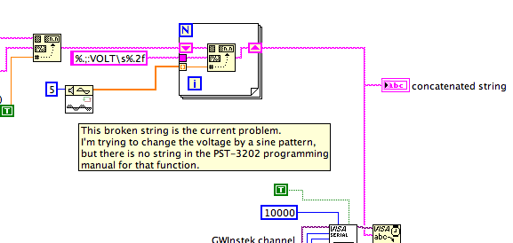
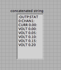
Hi all! I have a programmable supply of GW Instek PST - 3202 DC. I want to test the resolution of temperature based on my power supply fluctuations. I started to write a VI to do this, but I don't know how to vary the tension the sine wave-shaped. I found the Wfm sinusoidal function in Signal Processing, but I don't know how to change the '1 d of double picture' which is the "double sink" waveform, which is where I apply the supply voltage waveform. The VI is attached.
The value of Format function will not accept a table, put it inside a loop. Use a shift register to add all the values in the table, to the string.
Lynn
-
Output of different analog signals through 4 outputs
Hi all
Exit 4 different analog signals from the PCI 6711 map: I need help. I intend to use the waveform function from the palette of analog generation vi. My goal is to be able to enter the 4 necessary functions, it sampling information and then leaving four available analogue outputs available to the Board of Directors. I saw the code example for the output on multiple lines, but it doesn't seem like he is able to create unique waveforms through the exits, they are all the same waveform. I've attached what I thought work, but I can not get my number of rows in the data to match my number of rows in the task.
Specifically, choose instance polymorphic Analog-> multiple channels-> multiple samples-> 1 D wave.
Your current instance you chose is for just a single line.
-
Problem in the stimulation of the op-amp circuit used to produce sinusoidal signal
The President complied,
I'm trying to stimulate these circuits in Multisim. .but I don't get the good output.in oscilloscope.../technotrix oscilloscope.
On the contarary when I used a bread-Board & checked the result... I was getting sinusoidal output...
Please help me about the same...
I guess that stimulate the op-amp circuits is really hard in Multisim. !!
Please find the attachment.
NUPSSHAH,
I took a quick look at these circuits.
In "wave sine generation.ms12" U1A, you pin 4 (V +) cable to Gnd and PIN 11 cable to + 6V (while all the other operational amplifiers are opposed). Is - this intentional or your circuit isn't correct?
Also, these seem to be the variety of resonance (where the change of phase of 180 is important) and can be difficult for any Simulator SPICE simulate, especially if the conditions of marketing and the stage (transfer function) is not perfectly modeled. I think this might be similar to a situation where in SPICES you need to 'launch' resonant Crystal, that is to say - you'll need to give it an initial energy and eventually it will start to vibrate. (See here: http://forums.ni.com/t5/Circuit-Design-Suite-Multisim/Crystal-Oscillator/td-p/1109026)
Usually with a Crystal, the model is relatively simple. The difficulty with an op amp, is that if you give him too much energy (in order to get to the ramp until the resonance quickly), simulation can go non-linear because of the cutting/saturation and the global simulation at this time is perhaps not reliable.
Please check your circuit again, but maybe you can try to use as a source of thermal noise + interactive SPDT switch to give it enough starting (and put it out if enough energy is applied)? Just an idea... If you see no brake once the source is turned off, the phase is probably off.
Database-> Signal_Voltage_Sources-> THERMAL_NOISE
Pat Noonan
National Instruments
-
The output of a PXI6602 signal is adjustable to continue once completed the vi?
I have a PXI6602 that I use to simulate a quadrature encoder signal, but the signal must be present for any longer that the vi is open.
The signal is possible to continue after the end of the vi while I can interogate the unit of the signal goes in and then stop the signal with an another vi once I finished?
David.
Thank you, James.
to solve the problem, I created a sub vi for the questioning of the unit and put it inside the vi creating the signal so that once the signal is present the unit data are recovered then the DAQmx responsible are arrested and cleared.
Kind regards
David.
-
Hello world
I'm looking to sample a signal using labview.
I produced a signal using the block "simulate signal" with controls for amplitude, frequency, etc., and have varified it works.
I want to taste this signal at regular intervals and store the data. Can someone explain how to sample a signal in labview?
I watched the white paper next, but he spoke more with the concept of sampling, rather than a tutorial on how to apply it:
http://www.NI.com/white-paper/3016/en/
I also looked at what follows, who even once, did not in fact a tutorial:
http://www.NI.com/Tutorial/3116/en/
I couldn't find anything in my research. If someone can point me in the direction of a tutorial for sampling it would be much appreciated
-
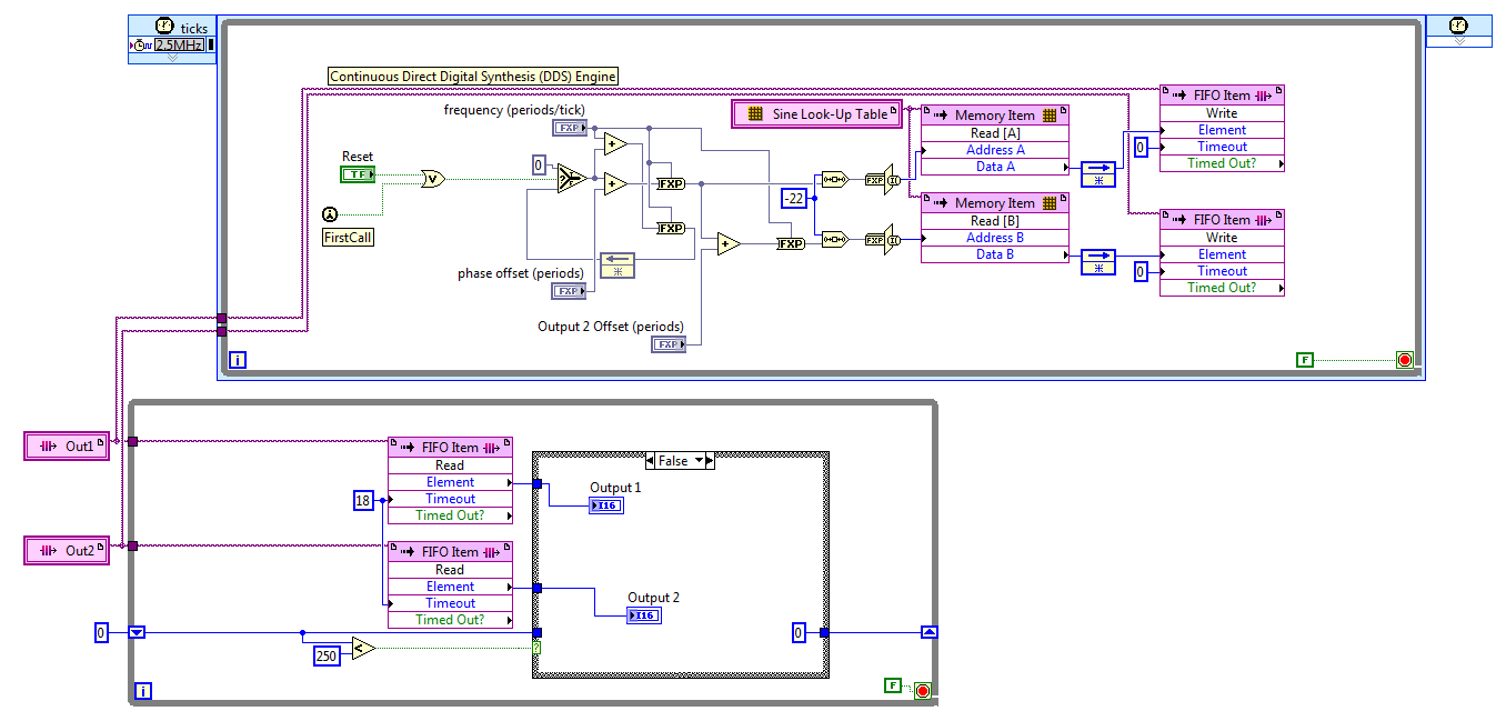
FPGA: Change the sinusoidal signal generator
The sine wave in the FPGA palette generator, that's what I need to do
but he can't exit do 'cosine', which is outside of 90 degrees. I need 120
degrees. To avoid discouraging, I opened the façade on the sine wave
Express VI generator that turned into a normal sup - vi. I changed the
a digital constant corresponding to 120 degrees out of phase, and the name was changed
of the output pin.The module will not compile. First mistake was a wire that was a type of variable, the
Fix suggested to check a box for pre-allocating did not work so I made the table
the length constant of 1024 (that is, it is supposed to be). Following error was
that one line of vhdl file was too long (32 k characters for a specification of length 4 k max
characters).Just for grins, I put the original VI Express return with the release of cosine and
It builds correctly.There was a big damper on the modification of the vi. However, I didn't know that
simple conversion to a subvi and the tweak of a constant value would break.Is it possible to get an updated the express vi for this application, or advice on how
changing the text that is there? The compilation breaks mainly online VHDL
length associated with the range of 1024 points.I can roll my own generator of sinus by using some examples, not a big problem but
It will cost you some time. Another option might be to run two generators of sinus
and specify a different phase, but I'm not convinced that over time they
will be exactly synchronized. Change the Express VI is a much better
option.Thanks in advance,
Bill
I discovered the hard way that LabVIEW 2011 has no records. After reviewing various options, I settled on the FIFO. The code presented here works well, but it is not save space on the FPGA to the wire using two generators of sinus with a phase difference in hard on one of them. For now, I'll use two sine generators, if this turns out to be unworkable in practice due to the relationship of phase adrift, then I'll look at it again.
The frequency and phase of the compensating controls are fixed point numbers formatted in zero whole bit and a 32-bit word. Bed down while the loop is synchronized with the loop timed by the FIFO, FIFO of 18 ticks timeout is two more than the 2.5 MHz in a loop which is a ditch-16. The IF block in the lower part, while the loop cut update control up to 10 KHz, 60 Hz sines more quickly.
Great experience, thank you for the help.
Kind regards
Bill
-
Hello
I found an example of http://zone.ni.com/devzone/cda/epd/p/id/4182 and edited for my purposes. On this basis, I have 16-bit mono speech files with sampling rate of 16 kHz for a speaker attached to the output NI 9263 module. However, this forum is without volume control and the result is extremely strong. I have attached photos of my diagrams below.
NDS read Wave File.vi returns a 1 d mono 16‑bit whole array. I multiplied this table by a command button, so I could adjust the constant which I multiply with the table 1 d as I thought that the size of integers are related to the amplitude of the signal. However, reducing the constant only reduces the quality of the word and is still very strong.
Is it the right approach to reduce the volume? And if not, what? Thanks in advance
Yawei7 wrote:
I thought that the size of integers are related to the amplitude of the signal.
It's quite right...!
And your approach is perfect...! -
My computer does not have an audio output. There is no problem with the speaker
I tried to connect many speakers, but none worked. I don't know if the problem is with the pilot.
I open the CPU and found that nothing is wrong with the connection.
Hi Madeleine Richard.
1. did you of recent changes on the computer?
2 when was the last time it was working fine?
Method 1
See the link below and run the fixit tool available, check if it helps.
Diagnose and automatically repair audio playback problems
http://support.Microsoft.com/mats/AudioPlayback/
Method 2
If the previous step fails, then I suggest that you manually download and install the latest sound card drivers by visiting the sound card manufacturer's Web site and check if it helps.
How to manage devices in Windows XP
-
Setting up an audio I/o buffer continues
I'm relatively new to Labview and run to 2 problems that I can't solve. If anyone can help, that would be great.
I am creating a VI using the sound card that receives an audio input of a generator of sinusoidal signal (plugged into the mic port), transforms this signal in frequency and uses the output frequency a sinusoidal signal of a slightly higher frequency
I started using the example of e/s simultaneous VI and changed to my needs. (see annex VI) I'm using Labview 8.5 on a Pentium 4 3.0 Ghz PC.
I get 2 errors, is that your measuring device measures a signal Inf and means the Niquist theorem. I have a sample rate of 44100 Hz and 4410 samples but a contribution of only 100 Hz sine wave. I paired the sampling rate and samples at a ratio of 10:1. I'm sure that isn't true. You have any suggestions of best on the design of the buffer?
Also, I sometimes get an error message about the read.vi of sound entry "a task must be run to perform this operation."
In this case, I guess I've just been lucky. You should do something, like I did here http://forums.ni.com/ni/board/message?board.id=170&message.id=399671&query.id=277879#M399671
In this way the moment then you read the sound card is not so important. The buffer will prevent dataloss and error. If you get overrun memory buffer the card its task ID will become invalid if I remember correct. Like you, I struggled with the Labview sound system. But now it works fine. At least the requested Party. The exit part have I fixed it with a work around. A way that I've discussed here http://forums.ni.com/ni/board/message?board.id=170&message.id=403131&query.id=279026#M403131 and here. You can also use a free software for audio output. It's called waveio. You can find it here http://www.zeitnitz.de/Christian/index.php?sel=waveio. It works on XP but I don't know if it works on Vista. With this software, you can have up to four output buffers, and the clicks will be gone. Try stamps how much you need. I think that 2 should work fine
-
Analog output of signal generation custom
Hello
I have a VI that generates a signal from the values in an excel worksheet. I'm trying this waveform through an acquisition of output data. I use a box NI USB-6211.
I copied the exit code for the acquisition of data from other VI that generates a sinusoidal signal coming from an excel worksheet. This program works very well. (attached for reference - Analog Output VI + sinusoidal waveform)
I have two problems at the moment. First of all, I get error-200560 about waiting until the function, attached.
Second output amounts only to about 5.5 v instead of 9V specified in the data.
My VI generate several types of waveform according to selected tests, but I'm trying to get an output DAQ working with the first test, named "disconnection of the battery" work first before implementing it in the other tests so please ignore others for now. To run this battery select VI disconnect under tests select then direct to the attached excel (BD values under 10V) file.
I hope that I myself have pretty much explained, otherwise please ask for more! I'm new to LabVIEW so your help would be very appreciated.
Thank you very much
Parker
aeParker wrote:
I've made a few improvements to the VI but I always feel the DAQ 5 Cap output, 5V.
Dear Parker,
I guess that this statement is based on the values in the chart show, AO 0. However, this is not (necessarily) the voltage produced by AO 0, but rather the tension being sampled by AI0. If you look at the DAQmx create channel for the AI voltage channel, you will see that you have left entries Maximum and Minimum Value unwired, which means that they take their values default to + 5v and - 5v. This may explain the behavior of cutting that you observe. Try the + 10 and -10 wiring and see if that solves this problem.
Bob Schor
-
I have a DAQ Assistant configured to read 2 channels at the same time. When I have a graphical indicator of wire to the output, I see 2 signals mixed together. How I divided them into separate signals?
When I wire any type of indicator, it is show that a release of a single channel.
I want 2 indicators showing 2 different signals as expected from 2 channels configured. How to do this?
I tried to use split signal but it end by showing that 1 out of 1 signal two indicators.
Thanks in advance.
Yes you are right. I tried, but I don't have the result.
I just find the path. When we launch the split signal, we should expand it (split signal icon) by top, not the bottom. It took me a while to understand this.
Thank you
Maybe you are looking for
-
I just upgraded to windows 10 and now, my iTunes will not work.
-
I use two java applets in my web page (let's call them XMLPlugin and Designer). I create Java objects by calling method of the applet XMLPlugin 'createObject (< params >): var myObj = XMLPlugin.createObject (< params >); CreateObject method returns o
-
I installed Firefox 10 9 - when I load firefox my bookmarks bar does not appear even if it is checked in the menu toolbars on the view menu. If I uncheck it then re - check it seems, but it's frustrating because I have to do this every time I load fi
-
Acer aspire laptop won't start (at startup)
Hi I use my computer laptop girls right now because I can't go on mine at all its an Acer aspire 5315 visited with Home Basic. When you turn it on the Acer screen then screen coming says Broadcom UNDI PXE etc., c copyright 2000-2006, copyright 1997 c
-
Wrong version of Win 7 for the serial key
Hi, I have a laptop G62 (well my gf but I have EU this) and (she) having lost all the discs that came with it and the system is in need a reinstallation, I went ahead and read this thread, and then driections to an external site and dl had an ISO of