FPGA: Change the sinusoidal signal generator
The sine wave in the FPGA palette generator, that's what I need to do
but he can't exit do 'cosine', which is outside of 90 degrees. I need 120
degrees. To avoid discouraging, I opened the façade on the sine wave
Express VI generator that turned into a normal sup - vi. I changed the
a digital constant corresponding to 120 degrees out of phase, and the name was changed
of the output pin.
The module will not compile. First mistake was a wire that was a type of variable, the
Fix suggested to check a box for pre-allocating did not work so I made the table
the length constant of 1024 (that is, it is supposed to be). Following error was
that one line of vhdl file was too long (32 k characters for a specification of length 4 k max
characters).
Just for grins, I put the original VI Express return with the release of cosine and
It builds correctly.
There was a big damper on the modification of the vi. However, I didn't know that
simple conversion to a subvi and the tweak of a constant value would break.
Is it possible to get an updated the express vi for this application, or advice on how
changing the text that is there? The compilation breaks mainly online VHDL
length associated with the range of 1024 points.
I can roll my own generator of sinus by using some examples, not a big problem but
It will cost you some time. Another option might be to run two generators of sinus
and specify a different phase, but I'm not convinced that over time they
will be exactly synchronized. Change the Express VI is a much better
option.
Thanks in advance,
Bill
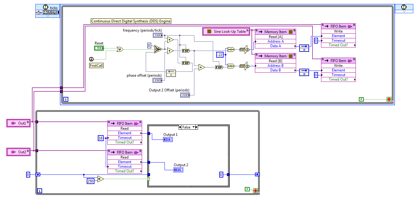
I discovered the hard way that LabVIEW 2011 has no records. After reviewing various options, I settled on the FIFO. The code presented here works well, but it is not save space on the FPGA to the wire using two generators of sinus with a phase difference in hard on one of them. For now, I'll use two sine generators, if this turns out to be unworkable in practice due to the relationship of phase adrift, then I'll look at it again.
The frequency and phase of the compensating controls are fixed point numbers formatted in zero whole bit and a 32-bit word. Bed down while the loop is synchronized with the loop timed by the FIFO, FIFO of 18 ticks timeout is two more than the 2.5 MHz in a loop which is a ditch-16. The IF block in the lower part, while the loop cut update control up to 10 KHz, 60 Hz sines more quickly.
Great experience, thank you for the help.
Kind regards
Bill
Tags: NI Software
Similar Questions
-
[FPGA] Problem with the sinusoidal signal generator
Hello!
At first I want to apologize for my English is not my mother tongue.
Hardware and software I use is:
LabVIEW 8.5
NEITHER RIO 2.4.1
NEITHER cRIO-9014 (controller in time real CompactRIO)
NEITHER cRIO-9104 (chassis and FPGA)
NEITHER 9264 (16 channels, +-10V, 16-bit voltage analogue output Module)
I made a very simple FPGA VI: a while loop, generator of sinusoidal signal and a FPGA of e/s node in the loop. I've specified the Gnerator settings by following the path:
Frequency = 50 Hz
Amplitude = 1
Phase shift = 0.00
Size of the table look-up = 1024
= 16-bit amplitude resolutionFPGA clock frequency (40 MHz)
But the wave of "sine" I got is not what I wanted to get. First of all, its amplitude is 1 V. shouldn't it be coded on 16 bits? If I wanted to get 1V I should have specified Amplitude as a 3277. In addition, 'sine' is not very detailed, it's look like "steps", as many samples vere missing. What I did wrong? I checked the samples and tutorials, I did everything the same way. A I forgot something or not has not specify other parameters?
Thanks a lot for your help!
OK, I solved a problem. It's embarrassing to admit, but maybe this will help someone else
 I blame my inexperience
The main solution to the problem was changing calibration of calibrated RAW Mode. After that, everythoing works as expected. I had a problem with a sample because I was using a multiplier to control the generated sine wave amplitude. But... She was set to 1 in the sinusoidal signal generator. That was the reason for waveform Gradin. Please, don't laugh too much

In any case, thank you for an answer! It is now resolved
-
Should I reset the FPGA FFT when changing the input signal?
Hello
I have an application based FlexRIO where I do FFT on several incoming signals. The signals will be ranked so that I get first for example 4096 samples of Ch1 and Ch2 4096 samples, etc. This means that I don't have to do it in parallel of the FFT and I would like to reuse the implementation of FFT and windowing to reduce the use of resources.
I intend using the VI Express followed by the Express VI of FFT window scaling
http://zone.NI.com/reference/en-XX/help/371599J-01/lvfpga/fpga_scaled_window/
http://zone.NI.com/reference/en-XX/help/371599J-01/lvfpga/fpga_fft/
and I'll use them inside a SCTL.
This figure comes from the section using the FFT and help illustrate the issue:
There is a discount to zero terminal for the fenestration and the FFT VI.
Are there internal registers in the windowing and FFT which force the image 1, image 2,... from the same signal or is it possible for the first entry in a framework of Ch1, the next frame belonging to Ch2, Ch3 gaze and so on and always get reliable results?
Another way to ask the same question: if I have to reset the window and FFT when changing the input signal?
Thank you
Anders
Hi Cyphish,
When using the FFT of the LabVIEW FPGA vi express and windows nationwide express vi calculations are make it point by point so there will be no problem when going through different types of measures. Therefore, you should have no problem with your application.
Best regards
Menelaos.K
-
Application of a policy of VSG when the vector signal generator is offline?
How policies are applied when a vector signal generator is offline, make port profiles with an attached policy start VSG to abandon all traffic until the vector signal generator comes back online?
VPath and vServices configuration
The default value of failmode is close.
Fail mode specifies the behavior when the MEC has no connectivity to the service node. The default fail mode for ASA 1000V and VSG is narrow, which means that the packets will be dropped. The default failure of vWAAS mode is open, which means that the packets will be passed. service nodes vPath 1.0 does not support service chaining. When you use a vPath 1.0 service node in a string, traffic to that node goes into failure.
Thank you
Responsible Dan
Cisco IDP data center
You want to know more about how the PDI can help you?
http://www.YouTube.com/watch?v=4BebSCuxcQU&list=PL88EB353557455BD7
-
How can blackBerry smartphones, I change the sound signal in BBM
I just got a 8520 only native of the United Kingdom. I can't understand how to change the sound signal for BBM. My daughter has the same phone, but the menus are different from mine. Can someone guide me through this process?
Drop down menu using the speaker on your homescreen icon and choose "Set Ring Tones/alerts. Inside the new screen, you should see a repeating field, called "Instant Messages". Expand it and you will have access to options for Blackberry Messenger. There must be 3 total.
Selecting one of the three will allow you to customize the BBM options. I suggest you change all three for the same parameters.
-
Problem with the biphasic signal generator
Hello!
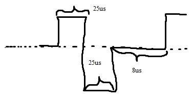
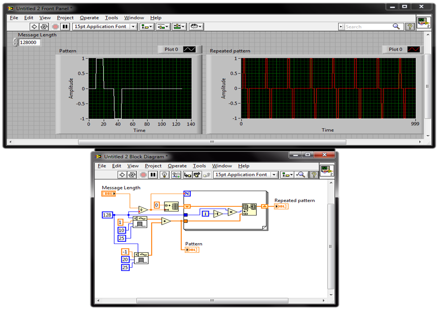
I filtered signal and detected envelope with OATS envelope detection.vi of given length. And now I need to modulate signal biphasic (photo). The biphasic signal should be the same length as my envelope signal. I want to be able to change the width of peak (25us) time and period, frequency (1 kHz), the biphasic signal amplitude (1). I know that I can start with pulse pattern.vi (check my diagram). But I don't know how to put together it me give only a single period. I have LabVIEW 2013.
You can repeat your profile of signals using a loop. Keep in the Middle the number of times where the model is repeted depends on the length of the theme of your message and the sampling frequency, you use the model and the message. Check this picture (just a quick suggestion):
best,
-
Change the structure of generated pivot table
Hello
Can someone help me change the model of PivotTable generated BI Publisher Desktop?
Lets' suppose I have a simple as xml:
< DATA >
< DETAILS >
< PERIOD > JAN-2010 < / PERIOD >
< ACCOUNT > 4111 < / ACCOUNT >
< SUM > 1200 < / AMOUNT >
< OPEN_PER_BAL > 0 < / OPEN_PER_BAL >
< / DETAILS >
< DETAILS >
< PERIOD > JAN-2010 < / PERIOD >
< ACCOUNT > 4112 < / ACCOUNT >
< SUM > 100 < / AMOUNT >
< OPEN_PER_BAL > 0 < / OPEN_PER_BAL >
< / DETAILS >
< DETAILS >
< PERIOD > Feb-2010 < / PERIOD >
< ACCOUNT > 4111 < / ACCOUNT >
< SUM > 1300 < / AMOUNT >
< OPEN_PER_BAL > 10 < / OPEN_PER_BAL >
< / DETAILS >
< DETAILS >
< PERIOD > Feb-2010 < / PERIOD >
< ACCOUNT > 4112 < / ACCOUNT >
< SUM > 102 < / AMOUNT >
< OPEN_PER_BAL > 10 < / OPEN_PER_BAL >
< / DETAILS >
< / DATA >
I can easily generate a structure with period like lines, account in columns and the sum as values. But how can I view OPEN_PER_BAL for each month at the end of the table?
Mountains/accounts | 4111 | 4112 | Open balance
--------------------------------------------------------------------------------------
JAN-2010 | 1200 | 100. 0
----------------------------------------------------------------
FEB-2010 | 1300 | 102. 10
------------------------------------------------------------------
Thank you in advance!
Published by: Simion on January 27, 2011 08:37Sorry, I got typo in the email address. The correct address is [email protected]
Thank you!
-
Change the time to generate a new key interval
Hello
Configure a lan-to-lan vpn between a sellers ASA and mine and it works, but the Phase 2 IPsec time key on my side is set to 28800 seconds and sellers is 86400. Is it possible to change my profile of connections to match anything? Honestly, I don't know if this offset will cause problems, but thought I'd ask.
Thank you
Hi Larry,
You should be on the cofig mode in order to enter the command.
ciscoasa (config) # crypto Outside_map 2 set security-association card second life 86400
-
local station changed the broadcast signal THAT WMC will not find.
MY frequency changed from local station cbs always on same channel 2.1 & 2.2 windows media center will not find the new frequency. they appear very hard on my tv tuner.
Help.BarbMVP - Windows/entertainment and connected homePlease mark as answer if that answers your question -
How change the bar signal strength dBm numbers
I know this has something to with the field test mode. But can someone tell me? Thank you.
IPhone SE 9.3.4

Dial the following:
* #12345 3001 #*.
-
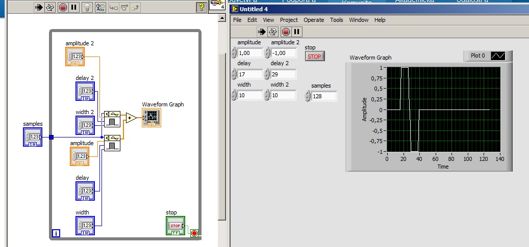
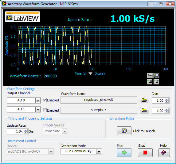
How to generate a pulse with the signal generator?
Hello
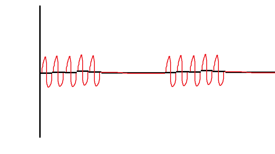
I would like to ask if anyone knows how to use the Elvis platform to generate a regulated pulse wave?
It should look roughly like the picture above. A sine wave with the regulation.
Anyone who can answer my question please respond to my post.
Thank you.
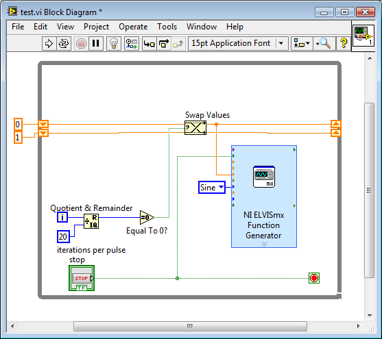
You are using LabVIEW to generate the waveform or using the Soft front panels? In LabVIEW, you can use the express VI generator function and specify the Type as "Sine". Then, simply change the amplitude of the sine wave. During the actual pulse, the amplitude would be what you want (i.e. 1 V) and while the pulse is idle, set the amplitude to 0.
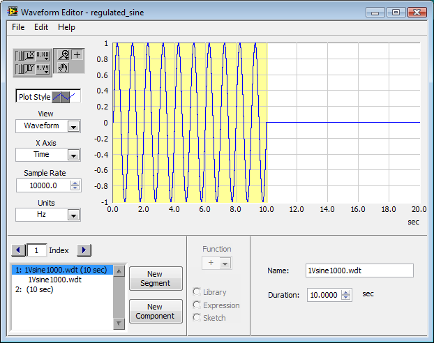
If you use the soft front panels, you can use the Waveform Editor to create a waveform that includes a sine wave for the length of your pulse and then the values of '0' for the rest of the time. Then use this waveform in the flexible front of the arbitrary signal generator. Simply create a component of sine as the first part of the wave and then add another element to a level DC '0' for the rest.
-
change suddenly current signal AO order
Hello
When I stop generate the analog signal, suddenly the current drive to AO increase or decrease strongly in the my range-25 to 35 my.
It happened to me several times. Suppose that when the stop signal generate, the current drive has become 0 my and when the signal to begin to generate, the active player became ~ 5 my.
How do I address this issue?
Hello yusof.
When you stop the AC signal, do you mean are you stop the task? If you only stop the task, the last value held constant until the value is changed or reset. I'd written 0Vs pay-per-view steps no matter what output signal.
-
Digital output frequency seems to be twice the frequency generated by the basic function generator
Hi Labview forum,
I wrote a program (attached) Labview to generate 3 PWM, square wave, signals that has the same frequency and phase delay right (so that when a signal is off, the other signal is lit. Then the next signal). Everything seems to work fine except that the frequency of the PWM signals generated seems twice as the frequency given to the basic function generator. Anyone have any idea why this is happening? Anyhelp would be greatly appreciated.
Thank you!
Totally agree with the advice of all GerdW than the hardware timing of your hardware DAQ will be much more reliable. That said, part of what you are probably hitting is a little quirk of the primitive delay msec. Requests for 1 msec have long been particularly little reliable (although they * seem * to have improved in recent years, probably due to the better OS support in Win 7 or something).
I did minimal mods to your code with comments from you switch to a timed loop. My quick test showed he is good enough to hit the 1 length of loop of target msec.
-Kevin P
-
If I can revise the SQL code generated by OBIEE
Hi all
I had a problemetic SQL generated automatically by OBIEE. I have to rewrite or at least add a tip to make it complete within a fixed period.
But I'm not sure if OBIEE offers us this feature to change or customize the SQLs it generates?
Please help to give some advice.
Thank you very much.
LeonHi leon,.
OBIEE increases the performance of the aliases table, cz as he can't do oneself joined himself.
Please visit this link this will solve your problem to improve performance
http://www.iwarelogic.com/blog/performance-increasing-OBIEE-724
(GOLD) http://www.rittmanmead.com/2008/11/thoughts-on-OBIEE-performance-optimization-Diagnostics/UPDATE POST
@leon, you cannot change the SQL code generated by obiee, your obligation to use EXISTS instead of IN operator, then you can do this in the physical layer of RPD by accessing the properties of the table and select SQL problem and write your query with condition EXISTS on the relevant tables. So that in turn Bi server accepts and converts according to its methodology.UPDATE POST-2
@leon, you can use rownum in your where clause, but check the query generated by OBIEE and the results obtained by rownum satisfied your requirment.Please follow label by awarding points to make it useful to others and even for us. Rules to be followed http://forums.oracle.com/forums/ann.jspa?annID=939
hope responds to your question.mark points.
See you soon,.
KKPublished by: Jocelyn on January 24, 2011 22:25
Published by: Jocelyne 24 January 2011 22:27
Published by: Jocelyn on January 25, 2011 02:13
Published by: Jocelyne 25 January 2011 05:26
-
How to change the colors of the Application Builder?
Hi all
I would like to change the colors of the Builder on my live server - just asking if I get not confused when I have both live and development sessions. It could be as simple that to change the logo to a different background color bar, so it makes it obvious which server I'm working!
I guess it's a matter of changing the topic, but I don't know where to look?
Thanks in advance
SteveHello
I know there is no way out of box solution to change the theme generator.
Probably more sure way is to change the css files in HTTP Server/i/css
But I would not bother to doHave you thought defined instance messages?
http://download.Oracle.com/docs/CD/E17556_01/doc/admin.40/e15521/adm_mg_service_set.htm#sthref361
You can also write HTML and add images for example.Or if you use Firefox, you can write a greasemonkey script client side to change the appearance of generator.
Kind regards
Jari

Maybe you are looking for
-
my look of the IPad 2 is locked. I want to erase and reset
my air pad 2 is locked, erased before using my itunes. i tunes won't recognize device not
-
Hello within 3 days my Skype webcam does not work and no body can see me, I would like to know how I can solve, Thank you
-
Synchronization of data from different sample of data acquisition rate
I use a high RT 8135. I'm sampling of signals from analog pressure thermocouples to 20 ms and 10 ms. I use the stream network to transfer the data from the SMU on my host. I would like to be able to synchronize the timestamps of all data to the 1m
-
The store where I gought this computer had these on special purchases and told me that I couldn't keep XP. I think that VISTA will not many of my programs like print shop ect. It does not open some of my XP disks did. Always open XP address book us
-
Does anyone know how to fix a CODE PURPLE error? My other three Hp / Compaq machines are ALL affected by this disorder. \ I need HELP, HP told me to run out and BUY retail any OS I want AND my pc are unter warranty hp!