output synchronization timing to trigger material (PFI)?
I would like to synchronize the output of my cards (2 PCI-6733 connected with a RTSI cable using BNC-2110) to the line AC from the lab I work in. In other words, when told to exit, they will always wait and exit at the same point in the cycle of 60 Hz.
To this end, I built a circuit which gives a TTL signal that is synched to the construction sector. I now need to find a way to take this TTL signal and use it as the starter for my experimental sequence. If there is a delay that's ok, however there must be a uniform period (in in microseconds preference). This is so that whenever I launch my experimental sequence, I start at the same point in the cycle of AC power.
Is it okay to use PFI port to try to do? Other suggestions?
The sequence would be:
Step 1: The cards are ready to write
Step 2: Maps of write once, started by the TTL of the circuit hardware trigger, I built.
Step 3: Other code runs Labview and then return to step 1.
OK, I got it working. The working example is attached.
The main thing was to writing after the left trigger vi. If someone wants to synchronize their experience on the power of their building (or any other source of relaxation), I confirmed that works this way.
Thanks for your tip Peter-E.
Tags: NI Software
Similar Questions
-
Timed by analog material out with PXI-6733
Hello
I'm a little confused on the possibilities for the material of analog timing of release of a PXI-6733, using pulses of DIO to a separate device.
I want to generate an analog voltage on the signal for synchronization from another device.
Lets say I want to generate tensions: 0, 1.3, 8, 0 volt. Sometimes 1 US, 402 U.S., 1004 US, US 1503. (we = micro seconds). I DIO card that will generate TTL pulses in these moments there and let's say I have the latter on a trigger PXI, PFI line line or enter the map of 6733.
How to configure DAQmx with labview to perform this task?
Thank you
Paul.
Hi Paul,.
There are many ways we could do this. The first thing that comes to mind is to sample AO clock battery LIFE of your device. All you have to do is do an array of doubles with the values that you want to scroll through and then then whenever you get a clock pulse we will update the output. You can see examples in LabVIEW by going to help > find examples. "" "The NOR example Finder will appear, and you can find many useful programs in input and output material" DAQmx "analog generation ' record of tension. To achieve my method, I opened the Gen Cont tension Wfm - Ext Clk.vi example and modified the code as indicated. I have included the code here for your reference. In my code, I plug my external clock in the clock via PFI0 source on my card. Now, whenever I get a pulse I will update the output voltage of 1 to-2 to 3-4, 1-2, etc., ad infinum.
-
Install error "unable to dΘmarrer pcpu 1; Synchronization timed out TSC.
try to install ESXi 6 and it generates error: "unable to dΘmarrer pcpu 1; Synchronization timed out TSC.
has tried all possible combinations of CPU config in the bios
OK, his works now
After you turn off the e-sata, usb3 and audio
not sure that it helped
-
Module AO trigger using PFI on the cDAQ-9188
I use a cDAQ-9188 chassis with an AO (NOR-9264) module. Is it possible to configure a PFI (channel on the frame) as an input signal to synchronize an AO channel with the trigger? Here's what I'm trying to do. I need a channel on the AO module to switch voltages in sync with the trigger when the user "push a button". So once the button is pressed, the channel of the AO will not change until the next trigger pulse.
Thanks for your help
Ben
Hello Ben
I hope you are well. The consensus is that it is possible. Have you tried this yet? If so, can you tell me what you have tried and how you made a lot of progress? I recommend the following VI example: Cont Gen tension Wfm - Ext Clk.vi. Are you able to get all the functionality you are looking for this VI. It was recommended that I'm showing you this. We find this VI under help--> find examples and then material input output &--> DAQmx-->--> voltage analog generation.
Please let me know how you are progressing and if you have need of all aspects of this example explained. Thanks for choosing National instruments!
Sincerely,
Greg S.
-
analog input and output synchronization
Hello everyone, I seem to have a problem of synchronization of the analog input and output on my M-series USB-6211. My request is quite simple. I want to the production and to acquire a sinusoid at the same time. Theoretically, I should have the same 4000 data points through the input and output channels. The reality, however, captured on an oscilloscope, shows that the analog output is off more than 4000 data points. The entry (acquisition) shows 4000 samples. Please see below an excerpt from the creation of task, timing and execution. I'm afraid that the analog input and output are not attached correctly. Do you see something suspicious? Thank you very much! The task was created: DAQmxCreateTask("",&inTaskHandle); DAQmxCreateTask("",&outTaskHandle); Analog output channel Configuration, with 20Ksamples/s: DAQmxCreateAOVoltageChan (outTaskHandle, physChanOut, ' ',-10, 10, DAQmx_Val_Volts, NULL); DAQmxCfgSampClkTiming (outTaskHandle, "OnboardClock", 20000, DAQmx_Val_Rising, DAQmx_Val_ContSamps, 4000); Configuration of the analog input strings: DAQmxCreateAIVoltageChan (inTaskHandle, physChanIn, "", DAQmx_Val_RSE,-10, 10, DAQmx_Val_Volts, ""); DAQmxCfgSampClkTiming (inTaskHandle, "OnboardClock", 20000, DAQmx_Val_Rising, DAQmx_Val_ContSamps, 4000); Set up the trigger: sprintf ("/%s/ai/StartTrigger", local_port, deviceName); DAQmxCfgDigEdgeStartTrig (outTaskHandle, local_port, DAQmx_Val_Rising); Output: DAQmxWriteAnalogF64 (outTaskHandle, (numberOfSamples * oversample), 1, 40, DAQmx_Val_GroupByChannel, input, & sampsPerChanWritten, NULL); Acquire: DAQmxReadAnalogF64 (inTaskHandle, 4000, 40, DAQmx_Val_GroupByChannel, readArray, 8000, & sampsPerChanRead, NULL); The tasks stop: DAQmxStopTask (outTaskHandle); DAQmxStopTask (inTaskHandle);
Hello
Change the finished continuous sampling method seems to solve the problem:
DAQmxCfgSampClkTiming (inTaskHandle, "OnboardClock", 20000, DAQmx_Val_Rising, DAQmx_Val_FiniteSamps, 4000);
Also, I wanted to say earlier to write 4000 samples:
Output:
DAQmxWriteAnalogF64 (outTaskHandle, 4000,1, 40, DAQmx_Val_GroupByChannel, input, & sampsPerChanWritten, NULL);
Thank you
-
Camera trigger with trigger material GigE
Hello
Here's an overview of what I want to accomplish:
LabView - program starts and expected output frames GigE camera
-Hardware trigger leads, to camera, GigE, image display
-A few simple calculations is performed on each image to generate the average pixel value--> this average value is plotted for each frame
-Repeat the three steps above
Please see the attached VI. I put my camera settings successfully in MAX do wait an external hardware trigger. However, out of IMAQdx Grab2.vi inside the While loop is only a single image (even if MAX I put the Mode of Acquisition of multitrame - 255 images).
Any help would be appreciated!
Thank you.
-
Output at 120VAC solenoid trigger
Hello
I have 4 120VAC solenoid valves, working in 6.1 watts, requiring only 0.05 ampere. I want to control LabVIEW via a hardware DAQ device.
My doubt is if there are hardware devices out there that give a large part of output to trigger a solenoid ON / OFF?
If NOT, is it possible that I can achieve this?
Thank you.
A device of digital output (DO) is controlled by your PC to put a voltage on and outside. A relay is a switch that uses an electrical input, usually low voltage, but not always and generally low current (such as from a c) to switch a higher voltage or current signal - like your 120VAC to control your solenoid.
-
OR 9403: Digital Input/Output slows timed loop?
Hi all
I use a loop timed sample of 7 current channels (NI 9023), 3-channel (NI 9025) voltage at 1000 Hz in scan mode and it works fine. However, when I add for 8 output channels of the input/output module digital module NI 9403 for timed loop, CAPAS sampling cannot exceed 1000 Hz. According with time stamp data I wroten in file, it seems that I have in all ten milliseconds, I missed a miliseconds.
I would like to ask is there a reason for this? The digital I/o module affect the timed loop?
Thank you much in advance.
I'm not familiar with the FPGA code, so I can't comment there. However, I noticed that you call writing to text file twice in the timed loop. Can you only collect data and then write the files after the time loop? This would save a lot of time. For each entry, the program needs to access the hard disk, find the end of the file, add him and return to write on the hard drive. A lot of your time, especially since the files are getting bigger.
-
Data before release for NOR-6133 trigger material and acquisition continue?
I use the pxi of NOR-6133 can acquire data on 7 channels continuously with ai0 as the trigger without problems. The acquisition is triggered. What I have to do is collect a finite amount of data before triggering immediately until the trigger is detected.
Is it possible to do without the help of a software solution. I watched go over acquisition and using the integrated trigger reference but that is not suitable for my needs because it just seems to change the first section of data to be 'post trigger' to 'pre trigger.
A software solution that I already know how to do is the last resort to try to reduce the demand for processor and keep the hardware triggering.
Thank you
By using the "reference trigger" is the right solution.
So can you please explain a little more in detail why it does not work in your case?
Christian
-
Outgoing SFDC synchronizes Timing?
Hi people,
I am new to SFDC together with SalesForce integration, so I have a small question which I hope someone will answer.
I believe that incoming automatic synchronization happens every two hours, or even you can configure these schedules accordingly to meet your needs. But what about the events. If I set up an event, for example update a contact in SFDC field after a contact update Eloqua took place, when this update will actually take place? Eloqua will send the update to SFDC immediately or is there a regular schedule that is running even there at - it somewhere that you can see and edit as approriate? Reason IM asking is because I changed the outgoing integration, i.e. to update another field, and I know that the customer will test it, so I want to make sure that when the update should actually occur.
All opinions are appreciated.
Kind regards
Andrew Mc.
Andrew-
Incoming Autosyncs that I believe are in 2 hours as best practice by partners of Eloqua SMartStart; However, it is unique to each business case. I always increase speeds and have the synchronization "Get Converteed leads" run every 30 minutes.
In any case, bound can't as an automatic synchronization, outgoing external calls that must be triggered by automation, as through program generator are. The speed at which the data written to the eloqua table contact and then go through all the stages of the program and finally reached your call to exernal to SFDC depend on a few factors:
1. the effectiveness of your program. How well-designed is it and is it using fewer steps? (conditional steps rather than decision rules, many others)
2 mode of operation of the program, the priority mode standard mode (15 min per step) (5 minutes for steps), products of mode (every two hours, all measures at the same time).
3. the speed of your program contact express, team and enterprise edition / database sizes have the speed, restrictions that get more than you pay.
So to answer your question, there isn't a queue or a schedule for out them, but there are factors that occur before hand which may slow down your pace (with good reason)
-
How to delay a PXI-5122 trigger before routed to string of PFI
Hello world
I use a PXI-5122 in a PXI chassis. I want to synchronize with two external devices. The first will send a trigger (with a 10 Hz repetition rate) for PXI-5122. Then PXI will generate a trigger (with a constant delay) in the second.
It seems that I need to generate a trigger, then export this trigger to PFI 0 line, but I do not know how to delay triggers with a timeframe of 4µs. I read that there is a slight delay between a trigger on the PFI and the first sample. And the length of the cable is also an important factor to consider.
Could someone give me some suggestions?
Wednesday,
Thanks for the drawings, that helps a lot! Somehow, I see this work (how to set up the scanner):
1. set up the record length to be 12us (4us trigger samples, 8us after outbreak). If the sampling frequency is 100 ms/s, that would be a record length of 1200 samples.
2 configure the position of record reference to 33%. That's how the digitizer breaks 1200 400 samples according to trigger before triggers and 800 samples.
3. configuration of triggering immediate reference. This will allow the acquisition of trigger the moment she gained 400 before triggering samples.
4. export the "reference trigger (Stop)" to send to Device_2. This output pulse is of variable width, so if you want consistency, you will need to the Device_2 trigger the rising edge of the pulse, did not not fall m. Once 400-pre-trigger samples are acquired, this impulse will be sent, and then the scanner will be immediately habitable after initiation of sampling.
5 configure the trigger of the entrance of Device_1 (10 Hz trigger), as the 'Advance trigger' and 'Start Trigger'. This will make the digitizer wait this impulse to start sampling before the next record. We set up, the relaxation of beginning to the 1st record and the trigger in advance for all subsequent records.
This facility should allow a pretty decent timing, but please test to be sure that it will be sufficient for your application.
Kind regards
Nathan
-
PXI5122
It is not very clear if I can do this, but it is
possible to arm the PXI5122 (pending a
external trigger) and a pulse output on
either PFI lines?
The PFI 5122 trigger material ext and
the 5122 will read the result.
I try to use the LOAN to START at EVENT
Which States 'generate a pulse when the digitizer is. "
initiated and ready to start the acquisition to start sampling '
TIA.
Hello
Yes, you can use the niScope export Signal.vi to produce a digital on one of your lines PFI pulse when a certain condition is met. From your post, it seems that you may already use this VI. I have attached a screenshot of the Signal VI export and included context-sensitive help and detailed about what parameters to signal help is available.
-
The value of static output on PFI on USB 6366
Hi all
What I want to achieve is to save dedicated 8 DIO lines on dev USB6366 on port 0 for some specific application and use remaining 16 PFI lines control some external equipment.
All I need is the ability to set some PFI line high/low within a reasonable time by command software (LabView, .net, C, whatever). No requirement special timing, just set some PFI lines high and LOW back switch after not less than 20 ms. These signals would be used to control an external logic; no significant current.
The question:
Is it possible to control the PFI lines in the way that I described on 6366 USB device?Manual for this device (or in fact, the family of devices) is a bit ambiguous on this subject.
It is said it is possible to select 'direction' of each digital line but that's it. No more information. Only a manipulation of the port 0 (general purpose DIO) has its own section. PFI-Out is just mentioned. PFI - In is explained a bit more in detail, but also vaguely.
P.S. I have no devices available now (I would have tested the ability to do what I described, if I had).
Thanks for your time!
Bebor,
You should be able to use the 16 PFI lines as digital lines. To change the status of the lines, you must create a task of digital output, the same as you would on the lines of port 0 (DAQmx manages the programming of the direction of line for you when you create a task). Writing DAQmx can then update the status of the lines.
These lines do not support the operation timed, so lines are updated when writing DAQmx is called. Synchronization restrictions that are imposed should be dealt with by your software and will be limited to the accuracy of the software timers put at your disposal.
Dan
-
Trigger multiple channels of PFI
Hello world!
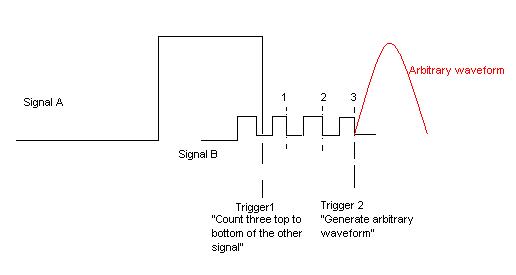
I want to create a trigger depends on two signals incoming (from external function generators) of PFI. Both are square waves, but the frequency is different. My wish is to trigger the slower from the top down as three top to bottom the faster and then generate an analog output. The picture is hopefully more descriptive than my words.
I use a NI DAQmx 6713 card. It doesn't matter if the solution is a LabVIEW VI or a C++ writes the text file. All the recommendations of good tutorials or similar is welcome. I managed to trig the arbitrary waveform after signal A or B, but I can't have the status of "County/wait three impulses."
Best regards
K. Berg
Hi K Berg,
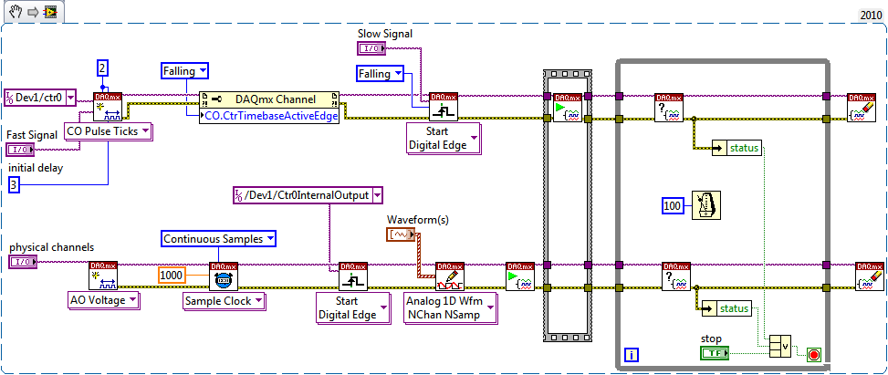
It is possible with the 6713 - you will need to use a meter of output to generate the trigger for your AO signal. Use your signal slow to raise the output of the counter. Use the fast signal for the time base of the counter with an initial value 3 delay ticks. The meter goes off on the edge of your slow signal and once that was triggered will generate a pulse after 3 ticks of the fast signal.
Best regards
-
Synchronization of AO and output counter, arming and triggering the sequence of events
Hi all
I'm trying to synchronize a counter (used as a digital pulse) and analogue of a custom waveform output read from the file on a USB-6211. The goal is to always have these running until I hit 'STOP' and to be able to change the position of the pulse relative to each other. I created a VI by combining and modifying the Cont.Gen.Wfm.Int - Clk.Non - Regen.VI and the Continous.VI Gen dig Pulse Train and I'm now able to produce the two signals to the desired frequency, but I can't seem to get the "Initial period" to work correctly. The values that I come home do not seem to match what is happening LeRiz, and the spacing seems to vary from run to run (within each series is constant). In a previous post, Alfred has suggested:
"Trigger counter outputs out of the trigger to start AO and adjusting the setting 'Initial period' should give you what you are looking for." Don't forget to start the tasks of meter in the software before the tasks of the AO (if they are armed and ready to go before the start AO is sent). »
I tried to use the controls and the propertynodes (perhaps incorrectly), but it doesn't seem to make a difference.
I think what happens is that my arms and firing sequence is not done correctly. I read on as much information as I could about the outbreak and armament, but I don't know that I understand correctly. Most of the examples I found using an external trigger or perform analog input tasks finished. Does anyone have a suggestion on how to start my two tasks in the proper order? Is something else is wrong here?
Thank you
Gabe
P.S. I have attached the VI and a sample waveform read.
Hi Gabe,
This is a cleaned of the VI version that should work (you need not adjust the initial deadline on the right fly?). Instead of reading a file, I made just a simple square wave of 50% to be used for the test.
Best regards
Maybe you are looking for
-
I have iMac 5 k mid 2015 upgrading memory
How to upgrade memory on iMac 5 k mid 2015 10.11.3 el capitan bones of 27 inches
-
Satellite A500-138 - lighting buttons does not work even in the BIOS
Hello. I'm just curious to know if anyone else has a problem with the (play/pause excatly) multimedia keyboard backlight? Mine died today, and there is nothing I can do to make it work again. The key still works, but when I turn on the backlight, bac
-
Receive error that No Optimum mode when you play a game
Original title: screen resolution Whenever I play a game, a window appears which says not optimum mode. I've adjusted the screen resolution, but it still doesn't work. The game will be played again except for the window that appears every time and
-
The share of customers unable to access the network - error 0x80004005
Hello, my network has the following configuration. Server - Windows 2003 Server - acting as DNS, domain controller, file server Clients - Windows XP Pro, Windows Vista business, Windows 7 Pro DHCP server is on my router. All customers running on DHCP
-
BlackBerry 9300 Smartphone trackball does not
does anyone have a miracle solution? Thank you