Output at 120VAC solenoid trigger
Hello
I have 4 120VAC solenoid valves, working in 6.1 watts, requiring only 0.05 ampere. I want to control LabVIEW via a hardware DAQ device.
My doubt is if there are hardware devices out there that give a large part of output to trigger a solenoid ON / OFF?
If NOT, is it possible that I can achieve this?
Thank you.
A device of digital output (DO) is controlled by your PC to put a voltage on and outside. A relay is a switch that uses an electrical input, usually low voltage, but not always and generally low current (such as from a c) to switch a higher voltage or current signal - like your 120VAC to control your solenoid.
Tags: NI Software
Similar Questions
-
output synchronization timing to trigger material (PFI)?
I would like to synchronize the output of my cards (2 PCI-6733 connected with a RTSI cable using BNC-2110) to the line AC from the lab I work in. In other words, when told to exit, they will always wait and exit at the same point in the cycle of 60 Hz.
To this end, I built a circuit which gives a TTL signal that is synched to the construction sector. I now need to find a way to take this TTL signal and use it as the starter for my experimental sequence. If there is a delay that's ok, however there must be a uniform period (in in microseconds preference). This is so that whenever I launch my experimental sequence, I start at the same point in the cycle of AC power.
Is it okay to use PFI port to try to do? Other suggestions?
The sequence would be:
Step 1: The cards are ready to write
Step 2: Maps of write once, started by the TTL of the circuit hardware trigger, I built.
Step 3: Other code runs Labview and then return to step 1.
OK, I got it working. The working example is attached.
The main thing was to writing after the left trigger vi. If someone wants to synchronize their experience on the power of their building (or any other source of relaxation), I confirmed that works this way.
Thanks for your tip Peter-E.
-
I'm trying to get my vi to trigger, do not know where to add the trigger
I need a vi that can trigger using an analog front (1V), then produced a square wave (all square wave will do for now) and then show the extent of the wave. Attached is the code that I've done so far. Not sure how to get a trigger attached, or where to put the trigger on what I've done so far. Another question is where it is triggered since then, I have to add another generating the waveform to produce the trigger signal?
Any help is appreciated!
Hello
You can place a start trigger VI DAQmx in the code above, between the Timing DAQmx and DAQmx write screws and then set the trigger to "Analog Edge" type and specify the channel to trigger of (in this case, I think that you should use the APFI line on your map). Discover the 'voltage - output continuous' example ' If you need help implementation of this code, this example includes outputs analog with different trigger types in a similar setup to yours.
-
Trigger multiple channels of PFI
Hello world!
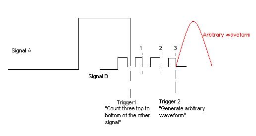
I want to create a trigger depends on two signals incoming (from external function generators) of PFI. Both are square waves, but the frequency is different. My wish is to trigger the slower from the top down as three top to bottom the faster and then generate an analog output. The picture is hopefully more descriptive than my words.
I use a NI DAQmx 6713 card. It doesn't matter if the solution is a LabVIEW VI or a C++ writes the text file. All the recommendations of good tutorials or similar is welcome. I managed to trig the arbitrary waveform after signal A or B, but I can't have the status of "County/wait three impulses."
Best regards
K. Berg
Hi K Berg,
It is possible with the 6713 - you will need to use a meter of output to generate the trigger for your AO signal. Use your signal slow to raise the output of the counter. Use the fast signal for the time base of the counter with an initial value 3 delay ticks. The meter goes off on the edge of your slow signal and once that was triggered will generate a pulse after 3 ticks of the fast signal.
Best regards
-
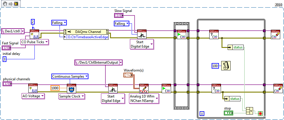
Synchronization of AO and output counter, arming and triggering the sequence of events
Hi all
I'm trying to synchronize a counter (used as a digital pulse) and analogue of a custom waveform output read from the file on a USB-6211. The goal is to always have these running until I hit 'STOP' and to be able to change the position of the pulse relative to each other. I created a VI by combining and modifying the Cont.Gen.Wfm.Int - Clk.Non - Regen.VI and the Continous.VI Gen dig Pulse Train and I'm now able to produce the two signals to the desired frequency, but I can't seem to get the "Initial period" to work correctly. The values that I come home do not seem to match what is happening LeRiz, and the spacing seems to vary from run to run (within each series is constant). In a previous post, Alfred has suggested:
"Trigger counter outputs out of the trigger to start AO and adjusting the setting 'Initial period' should give you what you are looking for." Don't forget to start the tasks of meter in the software before the tasks of the AO (if they are armed and ready to go before the start AO is sent). »
I tried to use the controls and the propertynodes (perhaps incorrectly), but it doesn't seem to make a difference.
I think what happens is that my arms and firing sequence is not done correctly. I read on as much information as I could about the outbreak and armament, but I don't know that I understand correctly. Most of the examples I found using an external trigger or perform analog input tasks finished. Does anyone have a suggestion on how to start my two tasks in the proper order? Is something else is wrong here?
Thank you
Gabe
P.S. I have attached the VI and a sample waveform read.
Hi Gabe,
This is a cleaned of the VI version that should work (you need not adjust the initial deadline on the right fly?). Instead of reading a file, I made just a simple square wave of 50% to be used for the test.
Best regards
-
I use a PCI-MIO-16-1, and I'm trying to create pulses on each of the three digital outputs, using a hardware trigger. I got a solution that sort of market by using a loop timed; the loop runs once per trigger, and inside the loop, I use avoiding to turn each of the three outputs at the right time.
However, the problem is that the 1ms resolution of the timing of software is not good enough. So I try to find a way to do it using equipment, so I can get a finer resolution.
What I tried to do recently is to create a redeclenchables on one of the counters pulse train (using the example generate digital Pulse Train-finishes-redeclenchables) and use it as a trigger for the timed loop. I can get the pulse train to give me three ticks for every time that I get a hardware trigger and then put a state machine inside the loop to turn each of the outputs. (I am currently divide the material into three equal segments trigger.)
However, although I can generate the pulse train very well on one of the counters, I can't manage to get the timed loop to use this counter as its source of the moment. How can I do? Or does anyone have a better idea how to do that?
Unfortunately, the card you have does not allow for hardware timekeeping DIO. M series and recent X series Multifunction DAQ devices allow such a task. If you want, I can have a technical representative contact you to discuss your request and provide appropriate suggestions to optimize your application.
Kind regards
Glenn
Technical sales engineer
National Instruments
-
DAQmx: synchronization of the two tasks of pulse output
Hey Gang,
I need to synchronize two tasks of pulse output. I use the PCI-6601 Counter-Timer. I need to use two tasks because the second output frequency must be a multiple of the first. I think that the way to do it is using arm Start Trigger functionality. I found some information on this site about it, but the examples spoke using a "dummy" analog task, I do not understand. I have found no documentation on the trigger to begin arms in the DAQmx documentation.
For reference, here's the enforceable part of my code:
TaskHandle DetHandle, LasHandle;
DAQmxCreateTask ("DetPulses", & DetHandle);
DAQmxCreateTask ("LasPulses", & LasHandle);DAQmxCreateCOPulseChanFreq (DetHandle, DetChannel,
"DetChan", DAQmx_Val_Hz, DAQmx_Val_Low, 0,0,.
StateSettings.DetFreq, StateSettings.DetDuty);
DAQmxCreateCOPulseChanFreq (LasHandle, LasChannel,
"LasChan", DAQmx_Val_Hz, DAQmx_Val_Low, StateSettings.Delay,
StateSettings.LasFreq, StateSettings.LasDuty);
DAQmxCfgImplicitTiming (DetHandle, DAQmx_Val_FiniteSamps,
StateSettings.DetPulses);
DAQmxCfgImplicitTiming (LasHandle, DAQmx_Val_FiniteSamps,
StateSettings.LasPulses);DAQmxStartTask (DetHandle);
DAQmxStartTask (LasHandle);DAQmxWaitUntilTaskDone (DetHandle, 10.00);
DAQmxWaitUntilTaskDone (LasHandle, 10.00);DAQmxStopTask (DetHandle);
DAQmxStopTask (LasHandle);
DAQmxClearTask (DetHandle);
DAQmxClearTask (LasHandle);
I think I need to insert the startup code of arms before the start of the tasks, but I do not know what device to use for the relaxation of the beginning.
I'll appreciate any help.
Thank you!
Roger
Hey Jorge and all,.
I appreciate the effort you do in my name. The simplistic answer proved to be using the correct syntax to specify the name of the terminal where the starting arm trigger specification may find the edge of digital triggering.
I use an output digital as the trigger (not shown in the code segment):
>>>>
Adjust the arm trigger for meter market
DAQmxErrChk (DAQmxSetArmStartTrigType (DetHandle, DAQmx_Val_DigEdge));
DAQmxErrChk (DAQmxSetDigEdgeArmStartTrigSrc (DetHandle, TrgTerm));
DAQmxErrChk (DAQmxSetArmStartTrigType (LasHandle, DAQmx_Val_DigEdge));
DAQmxErrChk (DAQmxSetDigEdgeArmStartTrigSrc (LasHandle, TrgTerm));The "TrgTerm" variable contains an array of char as "/ Dev1/PFI0" "EUREKA" discovery is that requires an oblique protagonist to work. In other functions DAQmx I used that was not necessary.
All of this consternation was absence of a single character ' / '. It would be nice to add this to the DAQmx database somewhere.
Best regards
Roger
-
I hope someone can point me in the right direction and also to clarify some concepts!
Background: I am currently using the box USB-6009 and labview on a laptop to output 2 analog waves. It acts as a waveform(0.5-2Hz) of speed (periodic) for an engine step by step (with a driver) to execute a loop of traffic, and the other waveform acts as a signal short 5V to trigger some imaging equipment. The ability to move or to delay the start time of the wave of 'trigger' compared to the waveform of speed in steps of hail (ms) became a requirement for my experiments. Given the time where the USB-6009 case, software based accuracy was not good enough because I need, and the way I wrote the VI limits my delay/travel at the speed of wave deltaT(30-40ms). I started to look at the USB - M series (portability is an obligation) since some have calendar based on the material, and I could send the signal to a buffer rather than iteratively having read every value of the wave in. It also seems that a digital short "pulse" works better than an analog wave form creating any. Where I ran into some confusion is to determine the requirements of a deterministic way sync the two. I am looking for new hardware. I started by looking at the box USB-6211. However, I ran across a few posts talking about the digital I/o correlated being required to perform vaguely similar configurations, which would require something more like the USB-6221. Since I have probably to the digital output to be on a time scale different analog output, is i/o digital correlated required? If not, would the 6211 work?
Just to be clear, I need the periodic waveform and relaxation to be constantly in phase (anywhere, 10 minutes to several hours). Then be able to move the pulse +/-1ms (minimum) and repeat. I can justify the most expensive device if necessary, but I don't want to get something I don't need.
I have attached a figure (not not to scale) of what I am after, in the likely event that my explanation was not too clear.
Thank you
Gabe
Hi Gabe,
The 6211 did not buffer IO digital as some of our other devices. However, there are two complete meters on the 6211 which can be used to perform a generation of pulses (pulse or continuous pulse train - you can output a pulse train using two counters finished). You can take a look at the section Applications of meter output x 621 manual for more information.
What it sounds like, the 6211 will do what you need for the following reasons:
1. the AO of the 6211 lines are buffered and can be clocked up to 250 kHz per channel (in contrast to the 6009 using AO NI by SW).
2 the 6211 counters can be used to generate two pulse based on a basis of time of 80 MHz (12.5 ns pulse width and resolution time). The 6009 does not output meter.
(a) if the two pulses must be on the same line, you must configure a task of generation of pulses finished' (this example uses two meters behind the scenes).
(b) if both impulses are on separate lines, then you can use a task to counter separated for each line with a different initial delay.
The 6211 does not supported clocked generation of digital signals (e.g. 100010101110100) but if you just need to generate impulses so that's precisely what the counters can be used to. I think that's where all the confusion, but seems like the generation of digital signals should not be necessary for your application. Trigger the counter outputs out of the trigger to start AO and adjusting the parameter 'Initial period' should give you what you are looking for. Don't forget to start the tasks of meter in the software before the tasks of the AO (if they are armed and ready to go before the start AO is sent).
I hope this helps, don't forget to post if you have any questions!
Best regards
-
NEITHER 6052e: can I re - route the analog output of DAQ for PFI?
Hello
Does anyone know if it is possible to route analog output to one of the PFI (e.g. PFI0)? I use NEITHER 6052e and I would do the following: 1) output a signal to DAQ0; 2) then a few hundred milliseconds a signal of DAQ1; and then 3) read out a simple analog pulse on any output connector external to trigger an external device.
Thank you very much for your help!
Hello sometimes.
Could you please provide more information about your hardware configuration:
What devices are DAQ0 and DAQ1?
Are you using a PXI and PCI 6052?
When you say AO reroute to PFI do you mean you're trying to wire AO into a PFI line for release purposes or are you trying to exit and the analog signal of a PFI line?
-
Timed signal generation TTL with the NI USB-6501 to be read by Arduino Uno
First of all, I want to apologize - I am very, very new to LabVIEW and brand new to the development of the software of control equipment in general. I tried to find an answer to this question already, but I'm not entirely sure what I'm looking for.
I have currently a work program LabVIEW which operates a gun card NI USB-6501. Due to the nature of having a machine that springs from a powerful beam of electrons, we want to assure you that if the computer controlling stalls or fails for any reason, we have built-in security that can stop the gun. Our current idea is to connect an Arduino Uno on a PIN on the USB-6501 and LabVIEW to generate a timed signal, which may read the Arduino. If the signal fails (indicating that the control computer has queued or off), the Arduino triggers a power relay that is independent of the control computer and turns off the gun.
I understand that the USB-6501 operates on TTL signals, so the signal that I should be something in the sense of "output TTL high, wait 1 second, output low expectations, a second, repeat TTL ', but I have no idea how to go about programming in LabVIEW. My first thought was that it is a square wave by using the function "simulate the signal" output, or to have trigger an iterative Boolean signal, by using the function 'DAQmx write', but I don't really understand how do to implement or another idea, or if an idea would even work.
Any advice would be greatly appreciated.
Hi Elizabeth,.
THINK THE STREAM!
When do you DATAFLOW think everything falls in places!

Several problems:
-You have to put that MAKE impulse VI in his own loop parallel to your main VI!
-When you place this generation of impulses in the effects loop ("TTL arduino low-high") you should put the CreateTask and StopTask outside the loop: no need to create/stop the task in each iteration.
-Why are there points of constraint to waiting functions?
-Why is there bent wires? You know Ctrl-U?
-LabVIEW comes with an extensive library of example screws: you looked at all these examples DAQmx?
-Suggestion: Learn more about the "structures of producer-consumer"!
-
How to get the name of the client computer and the name of the customer osuser
Hello everyone,
the trigger below works fine. But I want to get the name of the client computer and the name of osuser customer in the output of the same trigger shown below, how do I do this in the same trigger? any help is highly appreciated.
Thank you and best regards.
triggering factor:
------------
CREATE TABLE logonaudit
(
user_id VARCHAR2 (30),
sess_id NUMBER (10),
LOGON_TIME DATE,
host VARCHAR2 (20));
Table created.
CREATE OR REPLACE
Logon_audit RELAXATION
AFTER LOGON
WE DATABASE
DECLARE
V_program varchar2 (120);
BEGIN
SELECT UPPER (program)
IN v_program
SESSION $ v
WHERE audsid = sys_context ('USERENV', 'SESSIONID');
If (upper (v_program) as 'TOAD %' or upper (v_program) like '% SQLPLUS %')
then
INSERT
IN logonaudit
VALUES)
user,
sys_context ('userenv', 'sessionid'),
SYSDATE,
sys_context ('userenv', 'host')
);
end if;
END;
the output showing sessionid, date, db user name, as a local server machine name.but I want osuser of customer names and the name of the client computer as you know connection of clients to the database of their machines.how can I achieve? any help much appreciated.
Published by: 938946 on December 25, 2012 12:15 AMAccording to AskTom - do not use audsid, dangerous - can be 'zero '.
-
Reset enter actions on the page?
All, morning
Creation of a small catchment, delivery non - LMS, where there are interactive elements on a page (click HERE, image shows hidden, then click HERE kind of thing)
Imagine page 1 is my introduction, page 2 has the activity, page 3 continuous, etc..
I have my activities works very well, but if my user goes to page 1, 2, 3, then returns to page 2, the activities (and hidden elements) is already completed and visible.
I need something that returns the page 2 it is 'clicked' State of origin at the entrance to the page.
Using Cap 6.0, some experience with stock advances, but this one left me speechless.
Thanks in advance
Each slide is an event on enter, an event on the output. Both can trigger a tip action, just like the event of success for an interactive object:
http://blog.lilybiri.com/events-and-advanced-actions
Lilybiri
-
Hello friends,
I have a question. I need to trigger an output of Myrio with a single pulse. After the pulse, the output will remain active. Then with another single pulse, the output will be switched off. Should what tool I use?
Thanks for listening,
Kind regards
David
Hi Davi08,
I did a little research for you answer and I found another "NI Discussion forums" forum that maybe can help you.
Try using this link, I think this will help you.http://forums.NI.com/T5/academic-hardware-products-Elvis/myRIO-digital-trigger/TD-p/3278560
Best regards
-
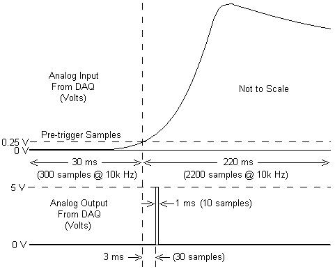
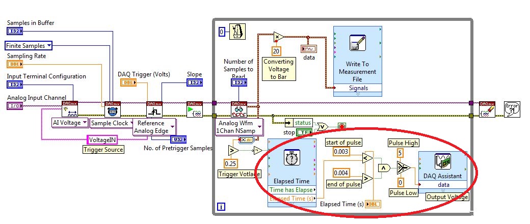
I am working with a combustion chamber and using a system of data acquisition (with the hardware OR SCB - 68) to read the pressure in the cylinder (such as analog voltage). I'm trying a pulse delayed, 1 millisecond to 5 volts of output once the pressure in the cylinder is high above 5 bar (which corresponds to an analogue voltage of 0.25 V). I would also like to record 30 ms samples before the trigger and 220 ms samples after the outbreak. The following image shows visually what I'm talking about.
I created a LabVIEW VI (which is attached), but I keep running into 2 issues:
- When I run with samples finished after a period of time, I get error-200281which I don't quite understand.
- Using the Express VI 'Out of time' to keep time for the pulse I can not get a resolution of 1 millisecond, the pulse is not generated when I put the window between 0.003 and 0.004 seconds for high pulse (i.e. the resolution of 'Elapsed Time' seems to be too coarse).
I'm a beginner to LabVIEW sorry if my questions are trivial or my VI makes no sense, but I was stuck on this during more than a week. Any help would be greatly appreciated!
Thank you
Morgen
This isn't a good way to trigger a pulse.
Use a trigger DAQmx to send the pulse when your acquired signal exceeds 250 mV you specified.See this for DAQmx trigger:
-
How to trigger and outputs analog and digital Outout tasks begins on a counter to start?
Hello
I'm trying to synchronize the start of a task outputs analog, a task of digital output and a task of counter. I want to start the counter to serve the master trigger and analog and digital tasks to synchronize his departure.
I guess I need something like:
analogOutputTask.Triggers.StartTrigger.ConfigureDigitalEdgeTrigger ("?", DigitalEdgeStartTriggerEdge.Rising);
digitalOutputTask.Triggers.StartTrigger.ConfigureDigitalEdgeTrigger ("?", DigitalEdgeStartTriggerEdge.Rising);
analogOutputTask.Start (); Slave 1
digitalOutputTask.Start (); slave 2
() counterTask.Start; n / / master
Where? is a string specifying a command source for the beginning of the task of the meter. However, I can't find what this string. Any suggestions?
Thank you!
-Jon
Just FYI, the solution to this problem as well as some other ones is encapsulated in a short example .NET, I created. It is on the Web site of EITHER:
http://decibel.NI.com/content/docs/doc-15500
This project shows how to synchronize all your analogue/digital outputs through tasks and forums in terms of synchronizing Calendar and start clock.
-Jon
Maybe you are looking for
-
Satellite Pro U300: Need to NDIS drivers to create a Ghost boot disk
Anyone has any hint where to get? I need to create a floppy disk to boot ghost to take an image of a satellite Pro U300 but cannot find the correct drivers to NDIS.
-
HP Envy 5530: HP Envy 5530 can print but cannot scan or copy
Hello After that I moved into a new apartment my 5530 desire is not scanning or copying (but I can print wireless without problem). I have already tried: -install the updated drivers -perform the reset -activate the static IP address -newtork reset t
-
problem loading Director of HP and other similar parts of the driver for 1315v all-in-one
problem loading Director of HP and other similar parts of the driver for 1315v all-in-one
-
all USB devices not working do not except keyboard and mouse
I have an ASUS 5275 CG and not the devices that I plug it into the USB works except the mouse and the keyboard please help!
-
What is the difference of the J2EE agent and agent Stand Alone
HelloI am a beginner in ODI tool and I'm deployment of the tool and I doubt plans the process.What is the difference of the J2EE agent and the agent of Stand Alone,which of the two I use.Thank you