output with quotes
HelloI have a table as below.
create the table members (member_id varchar2 (128), name varcahr2 (128))
Insert members (member_id, name)
Select '5591558906BA4A019FAB99EDAA26E62B', 'abc' from dual union all
Select '0F1E7A1B363111D3BDF20008C707ACC6', 'eur' from dual union all
Select '49C73ABC91404F8E825314FF6369E432', 'ure' from dual
I want an output with quotes
for example
If I have
Select member_id members
give me
5591558906BA4A019FAB99EDAA26E62B
0F1E7A1B363111D3BDF20008C707ACC6
49C73ABC91404F8E825314FF6369E432
instead I need output like this
'5591558906BA4A019FAB99EDAA26E62B '.
'0F1E7A1B363111D3BDF20008C707ACC6 '.
'49C73ABC91404F8E825314FF6369E432 '.
any help on this is much appreciated
Thank you
>
I want an output with quotes
>
Then put quotes in your query
select '''' || member_id || '''' from members
Tags: Database
Similar Questions
-
Synchronization of analog and digital output with the external sample clock
Hello
First of all sorry for my English, I will try to explain what I want to do.
I want my PCIe-6321 to send two custom signals (modification sawtooths) on a mirror controller. I would also like to generate output with my card at the beginning of each tooth of saw. Everything must be synchronized with an external k-clock signal of 100 kHz. The idea is that whenever the PCI receives a trigger to external clock, it sends two analog output voltages and when he received 1024 clock ticks it will also send a pic of triggering TTL. What I do is first prepare the map and after that in a loop sending and modifing the output values of the two signals and at the same time send a digital signal Boolean in each arch, so when's done it 1024 iterations of the loop I send an event to the digital port. Attached you can see.
The problem is that I don't know how to synchronize both. Can I use the sample clock just to the analog output? I can use sample for the two outputs clock, or do I need to use the output of the meter? If don't know how to use it here.
If I do nothing else bad/wrong, I would be grateful for feedback.
Thanks in advance,
PabloI don't know how but I find the solution. I'm generating more than a positive value (as I was triggered maybe very fast the oscilloscope has been absent there). If I put the sample clock of digital output to use the sampling/ao/Dev1 clock that it doesn't, but if I put to use the same source as the OD (terminal where my external clock is connected), but the trigger to start the DO to be Dev1/ao/StartTrigger this works. I don't really know why, but it does.
Thank you for your patience and your help. I put here the final code.
-
Analog output with counter Falling Edge
Hi all
Here's the iamge which describes what wishes to accomplish. I would like to trigger that the AO output with the edge of the fall of the meter.
I have set the clock for my AO as the counter.
The analogue output should be raised whenever the Digital signal meter falls
SAMPLE_SIZE = 80
SAMPLING_RATE = 40 #Samples are written every 25 milliseconds
TIME = float ((SAMPLE_SIZE) / (SAMPLING_RATE))CREATE TASKS
CREATE CHANNELS OF AO
CONFIGURE THE TIMING CHANNELS
DAQmxCfgSampClkTiming (taskHandleAO, "PFI12", SAMPLING_RATE, DAQmx_Val_Falling, DAQmx_Val_FiniteSamps, SAMPLE_SIZE)CREATE TASKS
CREATE A CHAIN COUNTER
# Time high-low + time equals 25 milliseconds and is proportional to the frequency of sampling
DAQmxCreateCOPulseChanTime(taskHandleD,"DAQ/ctr0","",DAQmx_Val_Seconds,DAQmx_Val_Low,0.00,0.005,0.020)# The values of voltage DAQmx writing
DAQmxWriteAnalogF64(taskHandleAO,SAMPLE_SIZE,0,10.0,DAQmx_Val_GroupByChannel,Voltage,None,None)# DAQmx AO task start
DAQmxStartTask (taskHandleAO)# Counter DAQmx Start task
DAQmxStartTask (taskHandleD)#TIME is equal to the total time for the writing samples
DAQmxWaitUntilTaskDone (taskHandleD, 2 * TIMES)I get an error every time that I run the task:
DAQError: Over Acquisition or generation has been stopped until the required number of samples were acquired or generated.

 function DAQmxStopTask
That's because my AO task is stopped for some reason any.
Is there an obvious problem with the code. Can it be structured differently?
best regards,
Ravi
I do all my programming in LabVIEW, so I'm pretty limited to help with programming syntax text. That being said, here's what I * think * I see:
Your AO task issues a call to DAQmxCfgSampClkTiming, but is not your task of counter. This probably leaves you with a meter spot which creates only a single impulse, which causes only a single AO D/A conversion. In LabVIEW when I need a pulse train, I would call a similar function of the synchronization with the clock mode is defined as 'implied '.
Hope this helps you get started, I don't know enough to give you the specific syntax in the text.
-Kevin P
-
Captivate & quot; padding & quot; output with grey window
I'm working on a project where my "movies" (it is the language of the version 1 of Captivate, I think...) must register in a Flash bodering framework (created by my client) which presents some special controls in this regard. I capture my project to 1010 x 574, to leave room for this adjacent image when end-users watch the result on their screens of 1024 x 768.
However, the published movie insists on in 1024 x 768 - top, bottom and sides of the window of desired content are padded with gray. that is, there are a gray bar along the top, a gray taller bar along the bottom and thin gray bars on the sides, by filling the frame out to 1024 x 768, even if my captured content is 1010 x 574.
It is therefore impossible for my client place the film correctly in their Flash of 1024 x 768 frame. First I thought that it would be the HTML code that Captivate generates... but it's actually in the SWF file. my client does not even use the HTML generated by Captivate, they use SWF files directly.
Last year, we worked on a number of movies using Captivate 1 and we never encountered this problem. (I just re-directed some old movies, to make sure that the problem is not there - it is not.)
I looked at the different options that are available to me when I "Post", but none of these options seem to solve the problem. (I tried the option "full screen", but which got worse, not better).
I hope I'm missing something simple here... but can someone give me a clue as to what it could be?
---
PS: I also checked my settings 'Resizing of the project'-'User defined' is selected, with 1010 width and height 574, which is, indeed, what I want - and the percentages are set to 100%. But my result, as I have said, is 1024 x 768 (with grey padding) rather than the 1010 x 574 desired. Makes me say arrgh.
Another PS: my screen resolution when I captured the screens was identical to the client monitor resolution 1024 x 768, "target." And my capture of 1010 x 574 window was visible (the usual red rectanble) in what I did my capture.Hi again
Certainly what you describe seems to me as if the HTML file is always in the picture. Here's why.
I created a little movie and put a yellow background.
Then, I set up the HTML page via the project > skin-> tab borders to be bright blue.
I then published. As expected, when I launch the application through the HTML page, the film is smaller, bright yellow, centered on a light blue background.
I then tested by right-clicking the. SWF and choose open with and choose a browser. In this case, Internet Explorer. What I saw when I did it was my film with no bright blue in sight.Maybe try the publication with the HTML export option disabled?
See you soon... Rick

-
Oracle Delimeted report with quotes "ss".
Thank you for your help in advance.
I am writing this report oracle 11 g. I want the output to format text with comma delimited by quotation marks double "ffffffff", "yyyyyyy" in a location of file is saved
I spent the following parameters to run the report object, the output outputs in text format, but without the double quotes. Although the single quotes appears when there is no trace in the column.
Can someone help please I want this result in double quotes.
run_report_object (p_report_name = > "My_report")
, p_parameters = > NULL
, p_format = > 'DELIMITEDDATA '.
p_location = > v_location);
SAVED_DATE, DESCRIPTION, REFERENCE, CLIENT_NAME, BENEFICIARY, AMOUNT, NUMBER, PROCESSED_DATE
17 February 16, 3rd party pleasure fresh, 16_84FTHOM-001THOM-001, Lydia Thompson, Felix Trinidada, ", 002345, 16 February 16
17 February 16, 3rd party pleasure fresh, 16_843THOM-001, Lydia Thompson, Latin Jo, 150, 342160, 16 February 16
17 February 16, 3rd party pleasure fresh, 16_841AREN-001, Gilbert Arena, Chistina, 200, 702991, 16 February 16
Thank you very much
In this way we do check this thread and try this.
Create a file wrapper.cmd on your server with a single line (I guess in /your_path/wrapper.cmd):
cellwrapper ="and also pass the delimiter =,
NOTE: Under Windows, you need to use single quotes around the quotes:
cellwrapper = ""' and also pass the delimiter =,
Using double quotes with the CellWrapper parameter to rwservlet
I think that this way your problem will be solved and separate report unnecessary file, you can do this in your file of same report also.
-
When I use in my css:
body: after {}
content: "mobile";
display: none;
}
And by controlling javascript with the command:
size var = window.getComputedStyle (document.body, ': after') .getPropertyValue ('content');I get in firefox (mac v 23.0.1) returns the '' mobile' ' string with double quotes as return and, therefore, checking if size == 'mobile' returns false. In safari, the value returned 'mobile' without the quotes. How is it?
What you get is a string that represents what you specified in the content.
A content specification can include other things like a counter: body: after {content: "subjects []" counter (topics) "]" ;}}
size = window.getComputedStyle(document.body,_':after').content would give: 'subjects []' counter (topics) "].
If you need test the exact text of the contents: size == ' 'mobile ""; -
I use the outgoing/incoming analog DDK with the DAQ 6341 SMU map.
The examples, for example aoex5, show a single timer (method outTimerHelper::loadUI), but the example shows the DMA loaded with same size of vector data.
There is a comment in the outTimerHelper:
 call rogramUpdateCount, which implies that memory sizes different pad per channel can be used.
(the comment is: switching between the sizes of the various buffers is not used)
Nobody knows what should be the format the DMA buffer for data from multiple channels with different frequencies?
For example, we want a0 with a sinusoid at 1 kHz and a1 with a sine wave of 1.5 Khz. What looks like the DMA buffer?
With the same frequency for each channel, the data are interleaved, for example (ao0 #0, ao1 #0; ao0 ao1 #1, #1,...), but when the frequencies for each channel is different, what the stamp looks like?
Hello Kenstern,
Data are always intertwined since each card has only a single timing for each subsystem engine.
To AO, you must specify the number of samples that will be released to the AO. You also specify the number of channels. Because he didn't is that a single engine timing for AO, each AO will be channel will be updated at the same time to update clock tick. Data will be interlaced exactly as shown in the example because each channel AO needs output at each tick of the clock to update. The data itself can change depending on the frequency you want to copy.
kenstern wrote:
For example, we want a0 with a sinusoid at 1 kHz and a1 with a sine wave of 1.5 Khz. What looks like the DMA buffer?
With the same frequency for each channel, the data are interleaved, for example (ao0 #0, ao1 #0; ao0 ao1 #1, #1,...), but when the frequencies for each channel is different, what the stamp looks like?
In your example, you must come with an update rate that works for the two waveforms (sine waves of 1 and 1.5 KHz). To get a good representation of a sine wave, you need to update more than 10 x faster than your fastest frequency... I would recommend x 100 if possible.
Update frequency: 150 KHz
Channels: 2
Then create you stamps that include complete cycles of each wave you want to produce based on the frequency of update. These buffers must also be of the same size.
Buffer 1: Contains data for the sine wave of 1 KHz, 300 points 2 cycles of sine wave
Buffer 2: Contains data for the sine wave of 1.5 KHz, 300 points, 3 cycles of sine wave
You can Interleave them as before. When the data are performed through the ADC, they are out different sine waves, even if the AO channels are updated at the same speed.
-
Triggers the analogue output with PCI-4461
Hello
I'm trying to generate a signal of analog output triggered with a card PCI-4461. First I tried to use the feature OR DAQmx 'start analog edge' with the way analog input AI0 as the source and the channel analog output AO0 as task. After it gave an error that I tried to use the NI DAQmx 'start digital dashboard' function with PCI0 as source and channel of analog output AO0 as task. It ran, but did not produce any output. Now I wonder if I can use the trigger analog or digital of the PCI-4461 to all of the output.
Thanks for support you,
Pribislav
Pribislav salvation,
you still have this problem? I did exactly the same configuration (power play) and it works fine on my system. The PCI-4461 does not support analog triggering, that's why this error occurs.
Kind regards
Michaud
-
Python DAQmx triggers a reaction of output with an input signal
Hello world
I use a NOR-6251 Board with a python GUI.
I want to send data on the output channel on each falling edge of the input signal when I click on a start button.
The level of the output signal may be 5v/0/1 (0v).
The frequency of input signal squares is 2 MHz for 50 on it (see the attachment for more information).
I don't know if it is better to use the analog inputs or input meter for the input signal. I think I have to set a clock pulse at the frequency of 10 MHz.
I tried several solutions with bad results.
Does anyone have the answers to my problem?
Thanks in advance.
Thanks for your reply.
It works...
-
Synchronization of the inputs and outputs with different sampling frequencies
I'm relatively new to LabView. I have a NOR-myDAQ, and I am trying to accomplish the following:
Square wave output 10 kHz, duty cycle 50%.
Input sampling frequency of 200 kHz, synchronized with the output that I get 20 analog input samples by square wave, and I know what samples align with the high and low output of my square wave.
So far, I used a counter to create the square wave of 10 kHz, display on a digital output line. I tried to pull the document according to (http://www.ni.com/white-paper/4322/en), but I'm not sure how sample at a different rate than my clock pulse. It seems that this example is intended rather to taste one entry by analog clock pulse. There may be a way to create a faster clock (200 kHz) in the software and use that to synchronize the analog input collection as well as a slower 10 kHz output generation square wave?
I eventually have to use the analog inputs to obtain data and an analog output to write the data channel, so I need the impetus of the square wave at the exit on a digital PIN.
How could anyone do this in LabView?
Hi Eric,.
All subsystems (, AO, CTR) derive from the STC3 clocks so they don't drift, but in order to align your sample clock HAVE with pulse train that you generate on the counter, you'll want to trigger a task out of the other. I would like to start by a few examples taken from the example Finder > Input and Output material > DAQmx. You can trigger GOT off the train of impulses, start by Gen digital Pulse Train-keep -you probably already use a VI like this to generate 10 k pulse train. AI, start with an example like Acq Cont & chart voltage-Ext Clk - Dig Start.vi-you'll want to use the internal clock so just remove the control of the "Source of the clock" and it uses the internal clock. From there, simply set the "Source of the command" either be the PFI line generates the meter, or ' /
/Ctr0InternalOutput '-assuming that you are using the counter 0. You'll want to make sure that the start of the task HAVE faced the task of counter I is ready to trigger off the first impulse. They should be aligned at this point. For debugging, you can use DAQmx export Signal to export the sample clock - you can then brought the train line and the PFI pulse to make sure that they are aligned.
Hope this helps,
Andrew S
-
Calculating the value of output with custom scale
Hello
I defined a custom in MAX scale.
I want just to calculate the value of an input applied with this scale value.
Process is simple:
X-online custom-online output value scale
in the process of
Is there a way to do it simply (reminder: custom scale can be linear, polygon, table etc...)?
Looks like you might need to check the interpolation
http://zone.NI.com/reference/en-XX/help/371361J-01/GMATH/interpolate_1d/ -
Analog outputs with different time scales
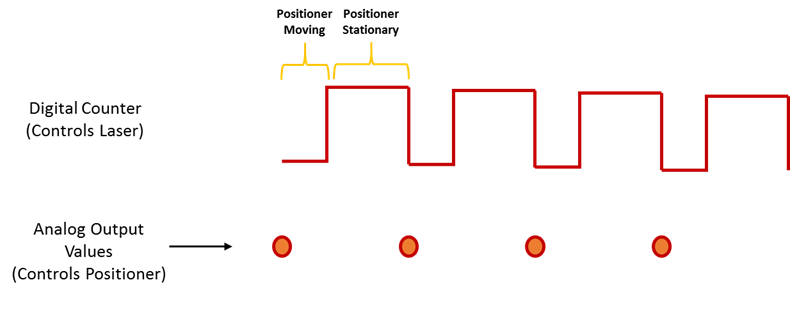
I use products AO of a card PCI-6731 for an application scan head and I have some difficulties to achieve peak performance, that I need. I am contolling the map with nidaqmx drivers in c ++
Basically, an output controls scanning in the direction Y (which is a line of scanning and is very fast) and the other in the X (increment once per scan line, so much slower). The complication is that both exits start at an external trigger, because positioning is synchronized to a separate data acquisition card.
Now, what I do is:
-write the scanline for 0 output waveform
-set output 1 to a given position
-say next Trigger output card
-hangs at the end and stop tasks
What I really want to do, it is just tell him to start with on each external trigger output waveform of scanline 0 and output 1 increment to the next position. So I could do a complete 2D scanner with a minimum of control software.
Any ideas on how I could best achieve this? My understanding of the nidaqmx drivers I don't see an elegant way to do it.
I could potentially do some operations on the done callback, although it makes me a little nervous because the control PC running windows, it is not a real-time operating system.
Hmm I do not know exactly but there are a couple of things (it is close)...
The output frequency of meter in your example 5 MHz (20 MHz, 2 high ticks, weak 2 ticks), which is faster than holders 6731 for a sample clock. I thought that this would have given a material error... are you looking for errors once the task runs (for example using DAQmxIsTaskDone)?. There is a DAQmxCreateCOPulseChanFreq if you want to set the clock frequency directly (it will use the appropriate default internal time base).
The task of counter generates 1000 pulses per trigger, is what determines the number of samples generated by the trigger (I assume that you want it to be 1024 aka "numSamples").
The analog output task must either use:
(1) calendar continuous if the output will repeat indefinitely as several triggers are acquired.
(2) finishes pitch (N * numSamples) samples where N is the number of lines that you want to exit and numSamples is the number of samples per line. In this case, the task will end once the lines were triggered.
Best regards
-
Digital output with NOR-9401 in cDAQ-9174
Hello
I have a cDAQ-9174 with an e/s digital NOR-9401 module. Now I want to output Digital signals on line0:3
$line0: Boolean 1 time = 10ms
Line1: Boolean variable 1 time = 20ms
row2: Boolean variable 1 time = 30ms
line 3:20 pulses (period = 250us, duty ratio = 0.5) after a time = 40ms
the value of line0:3 must be Boolean 0 after 45ms
Can someone let me know what I need to work to solve this please?
Thank you all for your help.
Concerning
Bing
Thank you Christian for your quick replay.
I have some experience in programming of microcontroller with C. I learned LABVIEW for about 1 month and followed a lot of demons in line and tutorials. I know that nodes DAQmx Data Acquisition screws and fundamental property.
As I said at the beginning on the $line0, lin1and line2, they serve to control the relay in my circuit. 10ms could be controlled with the OS clock. Pulse of line3 series is used for IGBT gate signals, which is the critical moment. I want to use the clock machine to accurately control line 3 and synchronize at the same time the pulse with analog inputs from an another two NI9206 modules in the same cDAQ chassis.
I just want to know more on the digital line demand signal relay output and a correlation between the line of analog input-synchronized finished pulse output. Waveform diagram is locked.
Thank you.
Bing
-
Using the output with 6009 or 6216 possible buffer?
Hello
I have a USB6009 and a USB6216. I need to generate a signal by using the analog output and I would use the output buffer. My questions are:
-The USB6009 has an output buffer? I always get an error, but I know from experience that this device is very limited, so I wonder if they have not only an output buffer... (Programs in input buffer are not a problem at all).
-J' took the USB6216 and I tried the example WfmGenUp.c downloaded from somewhere in the area of the developer (sorry I lost the link but fix the code) but I am not all analog output signals and after you press ENTER to stop the program (depending on the show) I get this error message:
NO MORTALS RUN - TIME ERROR: 'WfmGenUp.c', line 113, col 9, id thread 0x0000088C: DAQmxStopTask function: (is-200016 return value [0xfffcf2b0]). Measurements: On-board memory precision passing. Due to the limitations of system and/or the bandwidth of the bus, the driver could not write data to the device fast enough to track the rate of output of the device. Reduce your sampling rate, change the method of transfer of data (from interruptions on DMA), use a product with more on-board memory or reduce the number of programs that your computer runs simultaneously. Task name: _unnamedTask<0> Code of State:-200016
I don't know if the problem is just that the 6216 does not support the output buffering or the other...
-So, if the output control is not supported by 6009 or 6216 what would be the best way to constantly generate signals to 100 s/s?
Thank you very much
Kristel
Hi Ryan,
the USB-6009 case has 150 s/s softwaretimed AO, so you won´t be able to use AO stamped with the module.
The USB-6216 supported in the analog output buffer, just follow the recommendations that the driver gives you,
for example by reducing the sampling frequency, if there is an overflow memory due to the limitations of system and/or the bandwidth of the bus.
Experiment with the parameters and the basic to see in what range of sampling it works.
You can find appropriate examples
ANSI C:
C:\Dokumente und All Anwendungsdaten Users\Dokumente\National Instruments\NI - DAQ\Beispiele\DAQmx C\Analog Out\Generate Voltage\Cont Gen Volt Wfm - Int Clk ANSI
LabWindows CVI:
C:\Dokumente und Users\Dokumente\National Instruments\CVI\samples\DAQmx\Analog Out\Generate Voltage\Cont Gen Volt Wfm - Int Clk Anwendungsdaten All
-
Frequency of maximum output with USB-6008
I have a digital circuit containing 3 exits, 3 inputs digital and analog 1 entry in labview with my USB-6008. When I connect to the entrance (via the DAQ assistant) analog, the output frequency is reduced to a maximum of 27 Hz, but I need 50 Hz. is possible to do?
Ah. You'll need a DAQ better than the 6008, to do.
There is no train generation feature buffering or the pulse on the 6008. The outputs are all timed by the software, you cannot build a table and tell the 6008 in the output array. Out of the 6211 must be able to produce this signal. Series X-series Renault will do what it takes; the USB-6341 is probably your best option.
Maybe you are looking for
-
reinstalled Windows Vista on a HP computer with a Dell reinstallation DVD.
I have already downloaded all the HP software & drivers that I need to make it work like a HP., everything seems normal & tact except in the reception centre where it tells you all the details of your computer, it said its production is Dell & must s
-
U2412M, is no longer recognized by Windows 10?
Hello I have a Dell XPS and two monitors Dell, a U2412M and a U2415. Yesterday, I had to do a Windows 10 reset due to a software problem. However, now 10 Windows recognizes only the U2415. The U2412M he sees as a generic PnP monitor and sets a horrib
-
Run all the scans of the Diagnostics Bootable Lenovo's
I might be missing something obvious, but how do run you a full scan of a machine using Lenovo Diagnostics Bootable? AFAIK, you can scan only individually each component (memory, motherboard, PCI bus, hard drive, etc.). If indeed there is no way to c
-
Smart phone BlackBerry Smartphones BlackBerry will register (on Airtel with prepaid card)
Hello I tried to get the BIS enabled on my phone and so far have failed. I searched on the net and do not have anything conclusive. Basically, I am able to connect to the internet using my camera, but I'm not able to get emails or other data of work
-
FNMT certificate isn't valid in Adobe Reader
When I get a PDF document signed with certificate FNMT (legal Spanish Fábrica Nacional de Moneda y Timbre) it appears as 'unknown' in the PDF document. FNMT changed this certificate two years ago, and with the old certificates, this does not happen.