Partial switch outputs
Our client has a map of IO 6527 works through an SCB100 interface.
One of the outputs is connected to a door lock solenoid. Following the instructions 3:3, HiZ Port / Port 3:3, LoZ in its sequence, we measure the voltage to the solenoid 0 and despite a power supply of 24V 12V terminal + of this port. We have checked different voltages and I can confirm that everything is intact (for example, across the solenoid 0V is correct.) The side of the solenoid is in the specification of the relays in the solid state of the 6527.
Another way out is properly conducted a solenoid 0V/24V.
We tried to go to another exit with the same result. To our understanding, the solid state relays must be completely shut down or fully, so that we cannot see how we can get a half-out!
Although currently publishes the door locking, it is on the boundary of its reliability, and must be reported to the customer how to rectify the problem.
While I've never used this device, half voltage behavior is often an indication that something attracts much too common.
1. I don't remember to see a solenoid locking door with intensity less than 120 my. Very small door?
2 is 24 V AC or DC power?
3 did you measure the resistance of the solenoid? If this is an AC solenoid, measure the current with the plunger in various positions. AC solenoids with the piston not in place (due to mechanical obstruction or misalignment) can take huge currents.
Lynn
Tags: NI Hardware
Similar Questions
-
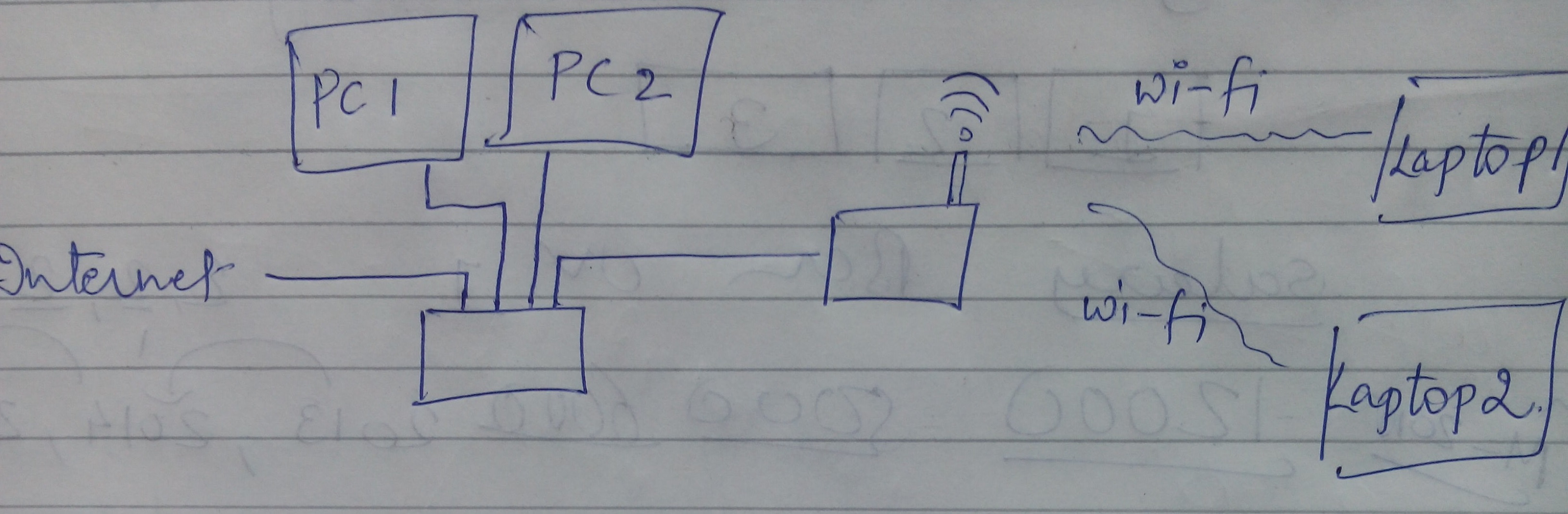
The Switch configuration and Wi - fi router in the same network
Hi team,
I have here is the configuration currently as below in the image. To describe the same internet cable is connected to a Cisco switch, which is connected to the PC in LAN (wired). A switch output is connected to the entrance of the wireless router Netgear Nighthawk AC 1900 Smart model of WiFi router # R6900. Wireless devices (laptop) are connected by the router.
Each device has internet access. However, I am unable to run software LAN or unable to share any file of devices connected to the switch to the connected wireless devices. I can't ping any device the device wireless wired.
Can anyone suggest what are the settings that I should do or what are the steps I should follow that will make wireless and wired devices in the same network.
PS Plus early I tried the internet connection to the wireless router and then out of the router to pass, which has solved this problem. But slowing down my internet speed in wired devices. So, is it possible to have all devices in the network even with the current configuration?
Thanks in advance.
Best,
Hardik
I made wi - fi router reset hardware and configured in Access Point mode, that solved my problem.
-
Coded frequencies-16 generator control switch
I feel really lame to ask this, but I can't understand how to connect a code switch to select 16 different frequencies in the generator module. I keep trying to figure out how with a switch output and a generator of output that I can control the generator of the switch. I can't imagine how the goes - inta and outta goes to get wired.
I keep thinking, I saw one such example, but can't find it

CJ, the example was everything I needed to make things work properly. It was logical that the output voltage of the coded switch would control the signal generator which he does very well.
Thank you very much!!!
-
Portege R930: cannot use the keys FN under Win XP
Hye
I'm French. I'm sorry, but my English is not good. I'll try to explain my problem
Yesterday, my boss gave me a new computer. It's a PT330E Portege R930-1FE with windows XP, 7 has been uninstalled
I can't turn off my touchpad. I can't use the Fn key.
I called technical support and after I downloaded the drivers for seven 32-bit and 64-bit... But I still have my problem
Please, you have a solution.
Thank you
Hello
Fn keys are controlled by special tools of Toshiba and depends on the running system.
Using Win XP, you need to install the common Modules and this must be done first. The common modules is an essential component of Windows systems.
He will perform the other original programming from TOSHIBA to work properly.Check this box:
[Common Module Win XP v6.07.03 | http://www.toshiba.eu/innovation/download_driver_details.jsp?service=EU&selCategory = 2 & selFamily = 4 & selSeries = 151 & selProduct 7565 = & selSh ortMod = null & language = 13 & selOS = 10 & selType = all & yearu pload = & monthupload = & dayupload = & useDate = null & mode = a llMachines & search = & action = search & macId = & country = al l & selectedLanguage = 13 & type = all & page = 1 & ID = 83752 & OSI D = 10 & driverLanguage = 42]To get the other buttons FN working (ie the screen switching output), you must install hotkey utilities for display devices
[Utility Hotkey for display v1.0.2.5 for Win XP | http://www.toshiba.eu/innovation/download_driver_details.jsp?service=EU&selCategory = 2 & selFamily = 4 & selSeries = 151 & selProduct 7565 = & selSh ortMod = null & language = 13 & selOS = 10 & selType = all & yearu pload = & monthupload = & dayupload = & useDate = null & mode = a llMachines & search = & action = search & macId = & country = al l & selectedLanguage = 13 & type = all & page = 2 & ID = 83758 & OSI D = 10 & driverLanguage = 42]In order to disable the touchpad, you need to install Touch Pad on / off Utility
[Touch Pad on / off Utility for Win XP v2.5.5.1 | http://www.toshiba.eu/innovation/download_driver_details.jsp?service=EU&selCategory = 2 & selFamily = 4 & selSeries = 151 & selProduct 7565 = & selSh ortMod = null & language = 13 & selOS = 10 & selType = all & yearu pload = & monthupload = & dayupload = & useDate = null & mode = a llMachines & search = & action = search & macId = & country = al l & selectedLanguage = 13 & type = all & page = 3 & ID = 83770 & OSI D = 10 & driverLanguage = 42]I recommend you to check the page of the Toshiba UE driver and install all the available drivers for Win XP.
-
I have a strange problem with my installation of motion control OR and I was wondering if someone could help me.
I have the following configuration:
PCI-7330 connected to an UMI-7764
Connected to the UMI-7764 I have two drives of P70530 stepper, themselves connected to two engines step by step from Nema-23 with encoders tree wired to the UMI-7764. While following the manual.
The switch "Inhibit the entry" is set to active top and switch "Output Inhibit" is set to active low.
The two discs P70530 initialize (solid green LED). The step by step and the engine performs on the terminals of the 'axis 1' of the UMI-7764 works very well. The other, performs on the terminals 'axis 2' does not work. When I try to run a query through MAX, the engine hear "click" once and then disengages. The reader is then a flashing green LED.
The engine will stay disengaged until I try a movement in the opposite direction, how the same 'click' is heard and the motor is now engaged. No movement other than the vibrations caused by the engine engage/disengage occurs.
Readers and encoders are wired identically in the UMI. I had the cables with the player that works as well as the discs themselves and even engines. The result is always the same; training/cable to 'Axis 1' engine works fine and 'axis 2 ","clicks"but does not move.
I would like some advice or suggestions anyone can provide, please.
After going back through all the threads, once again, I finally finished by checking the list of pins on the P70530 drive - > UMI-7764 cable.
It turns out that I had the wrong cable on the second axis. Part number 198151-2R5 instead of 198141-2R5. D - SUB connectors they are identical but different pinouts. After mapping the pins to the correct UMI axis terminals 2nd screw works now.
-
Calendar in a loop DAQ with write, read, then a bit of transformation
(I use a PXI-6052e, DAQmx and Labview 8.6. I have time real module installed if it would help to solve the problem that I have.)
I am writing a control program that requires a certain sequence in a loop, which is:
1 four of the digital i/o pins on the Board (to set the status of a switch), then update
2. to provide a boost to a brooch (to launch the failover), then
3. take a sample on each of the three analog inputs,
4. processing on these three samples and use the output to update maps.
Now, I know that, separately, my methods of control for the switch and the subsections of sampling/dsp doesn't work. However, when I try to combine them into the same loop there is a problem with the sync the sequence above. Clearly I'm not going to things the correct way.
I have attached the main VI containing the 'main measure loop' so that you can see how I'm trying to do things. The loop is in the last picture of the stacked sequence (the first two are just stuff of calibration - ignore them).
Ideally what I want is to have this loop running at 1 kHz (for example), and each iteration has the above followed by sequence [i] in that order [/ i]. To monitor the output pins and switch output but it is clear that this is not the case.
Thank you very much for any advice. I know that I'm doing it wrong, but I can't work on how it is supposed to be. I tried using a loop timed but in vain.
I've implemented the attached file. If you could have a look to make sure that's not crazy, it would be great.
I use two counters. The first is at 1 kHz and begins immediately. The 500 Hz counter is triggered to start on the front of the meter to 1 kHz.
Also, AI samples are acquired on each rising edge of the counter from 1 kHz.
In the future, I should be able to increase this to have a few more counters, I suppose?
-
First Photosmart C410: Ink series Photosmart Prem C410 leak
My printer is 5 years old, but so far it has been perfect - never had a problem with it!
Recently, I noticed there is ink in the printer and it seemed to come from the bottom. Further investigation revealed a bunch of ink which sank on the side right under where stop ink cartridges.
I don't know what is the cause, but it's a big mess in there and I don't know if it's interesting trying to clean up. (My fingers are already black cleaning of Office/below!)
I bought another printer but want to keep it too if I can. However, if it's too hard or too expensive so I am probably not worthwhile, especially given the age of the printer.
Here is a picture:
The area that show you is the 'service station' where little ink is "spit" to keep clear nozzles, usually before, during and after printing. It is unusual for this area of filling and too full, there are a few things that may cause excess ink in the gas station:
- With the help of an external power switch. If the power is off (with a switch output or other external) then more ink is used at startup. The printer must always be connected to a Plug and switch the printer only used to turn off the printer.
- Running "cleaning cycles. Manual cleaning cycles of the Toolbox Panel or printer are rarely necessary. They use ink and should be avoided except when necessary (almost never).
You may be able to clean the area of station service as follows: remove the print head and set it aside. Turn the printer off an area that won't have ink. Use a plastic spoon to remove most of the ink in the service area, making sure not to disturb the wipers. Rinse the service area, warm soapy water would be good for this, maybe a low pressure hose. Make sure not to get ink on thin coding tape (clear ~1/4"wide band that runs from the width of the printer). Also avoid ink or too much water in the electronics. After cleaning, dry the printer by dabbing gently with absorbent paper. Let dry completely before plugging the printer back in and reinstall the printer print head.
-
How to use the two counters to PXI-6280, to read and write at the same time?
Hi all
I try to use PXI-6280 counter to generate a command of step motor pulse train. The idea is to send a number done and known pulse for the engine, which belongs to a system XYZ. The point is, if, at some point, the user or the security system can interrupt the movement. If this happens (and will be... a lot), I will lose the real position, because I don't know how many pulses were actually sent to the engine. That is why I want to use the other cost to count impulses how were actually sent to the engine. I can start any tasks (generating or account), but only the first started task will operate. I met a couple of mistakes and I'm not able to find a solution.
Is it really possible to use the two counters? I've already done this in a pci system and worked without problems.
Thanks in advance,
Giavonna
Electrical engineer
I'm afraid that I don't understand your idea. Could explain you better?
Material of the series M support pointing to an arbitrary digital signals at rates (the clock must be provided from another source, for example a counter). If you want a digital pulse train finished output and have access to a counter (the two counters if find you another source for your clock, for example the subsystem "output frequency"), you must use this subsystem 'digital output' rather than the output of the counter. There should be examples in the finder of the example shows how to configure a finished task of digital output.
Now I'm generating sample clock having a single Timed material Point (the only mode accepts this mode), and configure the counter with finite samples.
I don't think not just single point NI the hardware, that's what you want. More commonly, output meter tasks use timing 'Implied', where the release date is implicitly determined by the characteristics of the pulse user-defined.
Is there a way to stop the production of only one meter when a finite number of pulses has been played in another counter?
Yes, but it's a little tricky. You can set a trigger 'Pause' on the output task, with the soruce the break being the internal release of the counter used for the task of entry. Set the initial value of the counter of entry to 2 ^ 32-N (or maybe 2 ^ 32-1-N, I don't have a system right now to check) where N is the desired number of pulse output. Together the counter event behavior for the counter edges of County switch output (this is a property of DAQmx export Signal). When the counter of entry reaches terminal, its in-house production switches, causing thus the task of output to pause. You can then stop the task in the software (you should be able to use the output of the task of entry counter event to signal to the software when the output is paused).
Now that I've written that the whole paragraph, I remember something * similar * to work around a limitation of the driver here . It is not quite the same implementation I described above, but really, you can use a meter output or a counter entry to get the same effect (it could be a good place to start anyway if you want to try this).
Is there a way to read pulses them how have been generated, without the other counter, counting impulses?
N °
Best regards
-
Reference Dell 6024
The switch has several local networks VIRTUAL, including VLAN 1 172.16.0.0 255.255.0.0 and VLAN 50 172.16.8.0 255.255.255.0. In the past, we have not need route between all the VLANS, but now I want to access the VLAN 50 of VLAN 1. All VLANS have a static IP address in the switch. Some configs:
SH ip route
Maximum parallel paths: 4 (4 after reboot)Code: C - connected, S - static, R - RIP, O - OSPF, E - OSPF external
C 172.16.0.0/16 is directly connected vlan 1
C 172.16.5.0/24 is directly connected vlan 2
C 172.16.8.0/24 is directly connected vlan 50
C 192.168.7.0/24 is directly connected vlan 40SH vlan
VLAN name Ports type permission
---- ----------------- --------------------------- ------------ -------------
1 1 g (1, 3-12, 17-24), ch(1-7) other required
2 phone switch g (13, 15-16, 24) permanently required
40 g (23-24) IDN Vlan permanent required
50 g (2,14,17) VLAN Voip permanent requiredThe router configuration
-----------------------------interface ethernet g18
Description ConfCtr
output
serial interface ethernet g (1-2, 17)
switchport mode general
output
serial interface ethernet g(23-24)
switchport mode trunk
output
database of VLAN
VLAN 2,40,50
output
interface ethernet g2
pvid switchport General 50
output
serial interface ethernet g (13: 15-16)
switchport access vlan 2
output
interface ethernet g24
switchport trunk allowed vlan add 2
output
serial interface ethernet g(23-24)
switchport trunk allowed vlan add 40
output
interface ethernet g2
VLAN allowed switchport General add 50 unidentified
output
interface ethernet g14
switchport access vlan 50
output
interface ethernet g17
VLAN allowed switchport General add 50
output
interface vlan 2
name 'phone switch '.
output
interface vlan 40
name "Vlan IDN.
output
interface vlan 50
the name "Voip VLAN.
output
interface vlan 1
IP 172.16.0.39 255.255.0.0
output
interface vlan 2
IP 172.16.5.2 255.255.255.0
output
interface vlan 40
IP 192.168.7.43 255.255.255.0
output
interface vlan 50
IP 172.16.8.2 255.255.255.0
output
the 172.16.8.2 interface IP
broadcast-address 0.0.0.0
directed broadcast to the
output
> Gigabit Ethernet ports
=============================
> no stop
> 1000 speed
> full duplex
> negotiating
> flow control to the wide
> auto mdix
> no pressure
> interface vlan 1
> interface port-channel 1-7
> no router RIP
> do not allow no router OSPF
> spanning tree
> spanning tree mode PLEASE> basic qos
> Host OOB Configuration
-------------------------
> out-of-band-eth interface
> no stop
> 100 speed
> full duplex
> negotiating
> flow control to the wide
> no pressure
> outputI can't ping from VLAN 1 to 50 of VLAN. Based on another poster who said that the VLAN 1 is not routable, I configured a port to VLAN 2 and tried to do a ping of 50 VLAN port, without success. I am really puzzled. There seems to be a fairly common config and I'm sure it's something really simple... but what? »
-
Web authentication Catalyst 2960
Hello
I am trying to configure Web authentication relief on a catalyst 2960 switch. The goal is to authenticate customers via web authentication that are consistent (the part of 802. 1 x works fine) not 802. 1 x and allow them access to the network. The problem is that the web authentication seems to fail.
The equipment about my question: switch catalyst 2960 (version: 122 - 37.SE) and a FreeRadius.
Here's what happens:
The authentication window will appear in my browser and the access request is sent to the RADIUS.
The term RADIUS replies with an Access-Accept. Debugging running on the switch show that all this information is coming properly authentication and switch outputs debug a 'status = PASS' and permission to debug outputs a 'status = PASS_ADD'. Despite this the browser on the client generates a message "authentication failure".
I have read the manual and the Cisco attribute value pairs are mentioned: ' priv-lvl = 15' and «proxyacl...»» ». They are required to make it work? Given that I'm not setting up any authentication switch connection via RADIUS.
Any suggestions?
Thanks in advance
Yes, they are mandatory.
If priv-lvl = 15 is not returned to the switch, the user will see? Authentication failed? and the access list will not apply. If the source in the statements of proxyacl field is not? everything? or there are other errors of syntax, the user will see? Successful authentication? but the access list will not apply and the user will be denied access to the network.
Not sure about the configuration of specific FreeRADIUS, but you need to set up the? [026\009\001] Cisco av pair VSA. It should look like:
Priv-lvl = 15
proxyacl #10 = ip permit a whole
Let me know if this lets you squared
-
Another issue of queues DSCP/QoS/CoS of 6500/7600
OK... a little confused, thinking, that I know what needs to happen, and what is happening now, but it is true UN-certainty with that I hope that people can help. Here are the basic configuration:
A---|6500|--10G--|7604|---10G---|7604|---10G---|6500|---B
You get the point. Traffic crossing A-> B or vica versa.
All the links of the kernel are L3/Routed, not L2/Vlan/.1q/ISL
Traffic is marked on the Board with a political map of penetration.
Traffic is confirmed through DURATION that it contains both CoS and DSCP/ToS, leaving the 6500 s two-way headed the core of 7600
Traffic is ALSO confirmed through extending classes * receipt * on the other side by the 6500, that DSCP is maintained but CoS is gone/0.
Considering that only 6708 - 10G modules allow apparently dscp values mapped to the queues/thresholds, which leaves me with the research of the queue on the penetration (for VoIP traffic priority) with cos-of-queue / beat mapping as well as output with cos to queue mappings. Of course, this is not possible (at least on the penetration) if the 7600 are not preserving the CoS on the output of the port.
This leaves wondering if the 7600 are same queue evacuation traffic based on internal mapping supposed DSCP-to-CoS that is supposed to happen before the queue/Scheduler. Interfaces are all set up as "trust dscp" right now. So the CISCO docs should be rewriting CoS to 0 on the penetration and using reliable dscp values to determine internal DSCP, which in turn should be used with DSCP-CoS map appropriate queue on exit... I am a sceptic, what happens really... and unfortunately, have really no way to verify (that I know) because the show on the 6500/7600 commands are fairly primitive about QoS stats...
Then, we have been re - think about it and thought that maybe the thing to do to solve this problem is to:
-Trust cos instead of dscp
-enable transparency dscp (no rewriting dscp) so it is kept on the side of the switch output
And so by doing this it would be:
-use CoS to tail of penetration
-use CoS to output queues
- And to preserve the original CoS and DSCP/ToS values
Would that be correct?
Two other config options I thought were:
-queue only mode
-mpls cos spread (although I don't think that would do what I want, but rather simply spread non-existent MPLS EXP bits)
Any help would be greatly appreciated... I read so many different docs now, my head is swimming
Couple of caveats-
(1) all the below apply to pre IOS 15, as I have no experience with which it may be different
(2) I have not used a 7600, but I used the 6500 much but both share a large number of the linecards and I suspect you're referring to this kind of linecards.
The main problem is that the CoS value is contained in the 802. 1 q non-native added tag VLANs on a trunk link. But your links are L3 if there is no value CoS to preserve.
This creates two problems for you-
(1) input queues. On penetration, the queues are CoS based which means you need to a CoS value to assign packets into queues. On the 7600 s you're obviously not see a CoS value for the reason explained. Now, you can use a political map and a service policy to classify and mark inbound traffic. But, as far as I know, you can set the IP precedence or DSCP marking in a map policy on traffic of the penetration. Some cards like cards ARE for the 7600 support defining a CoS value but I think they are the exception rather than the norm.
(2) output queues. You are right in what you say, IE. You can trust the DSCP/IPP incoming value and then, assuming that the line card doesn't support based DSCP output queue, the 7600 may derive a value based on the internal DSCP value CoS and then put in the correct output queue.
Yet once, however, without a trunk there no value written in the packet CoS.
I entirely agree that it can be very difficult to tell exactly what the 6500 in terms of marking internal etc. This is one of the great frustrations with the 6500.
Hope some of that helped.
Edit - the only way that you can trust CoS on penetration as far as I can see is to make the trunk links IE. you use a vlan dedicated for each interconnection and allow only that vlan on the link. Then you simply transfer the IP addresses assigned to the physical ports for the SVI to the new VLAN on each switch. You should make sure that the vlan that you authorized through the link was not the vlan native because you need a tag to add.
Jon
-
FWSM: Failover (Pseudo-veille)
Hello!!!
We run FWSM Firewall Version 3.2 (1). In context with failover (2 boxes of 6509) Interchassie multi mode
I have problem FWSM failover.
Zone primary sh switching output
****
This context: Active
Context of peers: failure
Secondary area shows
*******
Flipping out (Pseudo-veille)
Secondary failover unit
Failover LAN interface: faillink Vlan x (h)
Frequency of survey unit 1 seconds, 15 seconds holding time
Interface frequency of survey 15 seconds
4 political interface
Monitored Interfaces maximum 46 250
failover replication http
If someone please can guide with the
1 reason behind failover descended on the secondary zone
2. What can be done to recover from this State.
3. What are the effects of this if it is not recovered.
Thanks in advance
Concerning
Yogesh
India
Yes do a "write mem". It seems that you lack an IP address on the interface nattest and also you lack secondary VLAN Safeco and Bizco on the main switch.
Make a vlan show on the secondary switch and see if these VLANS exist and are ACTIVE!
Concerning
Farrukh
-
MAB authentication fails on the port of multi-domain: dead result of authentication "server."
Hi all
First of all, I have no experience with the configuration of Cisco switches (about half a year now) but I read loads and loads of documentation.
I am trying to configure several areas (MDA) authentication on our Cisco switches using mab and spin into something strange. Currently, single mab is asked by my employer.
Switch = 48-3560G IOS version 12.2 (55) SE1
RADIUS = Freeradius (version 2.1.10)
On port Gi0/29 a Cisco 7961 IP phone is connected and plugged into the phone that a laptop is connected
The switch configuration:
AAA new-model
!
Group AAA dot1x default authentication RADIUS
Group AAA authorization network default RADIUS
AAA accounting delay start
start-stop radius group AAA accounting dot1x default
start-stop radius group AAA accounting network default
!interface GigabitEthernet0/29
235 a description
switchport access vlan 4
switchport mode access
switchport voice vlan 2
load-interval 30
bandwidth share SRR-queue 10 10 60 20
queue-series 2
priority queue
action retry authentication event 0 failure allow vlan 7
action of death event authentication server allow vlan 4
living action of the server reset the authentication event
multi-domain of host-mode authentication
Auto control of the port of authentication
restrict the authentication violation
MAB
Auto qos voip cisco-phone
spanning tree portfast
service-policy input AutoQoS-Police-CiscoPhone
!dead-criteria 5 tent 5 times RADIUS server
RADIUS-server host 10.1.1.24 auth-port 1812 acct-port 1813
RADIUS server key 7 xxx
RADIUS vsa server send accounting
RADIUS vsa server send authenticationRadius response: (for the full reply see attached RADIUS - response.txt)
Sending acceptance of access to the port id 98 to 10.1.1.207 1645
Cisco-AVPair = "Tunnel-Type = VLAN.
Cisco-AVPair = "Tunnel-Medium-Type = 802.
Cisco-AVPair = "Tunnel-private-Group-ID = 7.
Cisco-AVPair = "Tunnel-preference.That's why access accept with assignment data VLAN
Debugging on the switch :
001776: * Mar 1 09:27:35.606: mab-ev(Gi0/29): context MAB received create from AuthMgr
001777: * Mar 1 09:27:35.606: mab-ev(Gi0/29): MAB authorizing MACAddress
001778: * Mar 1 09:27:35.606: mab-ev(Gi0/29): client context created MAB 0x2200000F
001779: * 09:27:35.606 Mar 1: mab: State has original mab_initialize enter
001780: * Mar 1 09:27:35.606: mab-ev(Gi0/29): sent to create a new context of EAP of MAB to 0x2200000F (MACAddress) event
001781: * Mar 1 10:27:35.606 THIS: % AUTHMGR-5-START: start "mab" for the customer (MACAddress) on the Interface Gi0/29 AuditSessionID 0A0101CF0000007F0207A4AC
001782: * Mar 1 09:27:35.606: mab-sm(Gi0/29): the event received 'MAB_CONTINUE' on the 0x2200000F handle
001783: * 09:27:35.606 Mar 1: mab: during the mab_initialize State, had 1 (mabContinue) event
001784: * 09:27:35.606 Mar 1: @ mab: mab_initialize-> mab_authorizing
001785: * Mar 1 09:27:35.606: mab-ev(Gi0/29): MAC-AUTH-BYPASS boot for 0x2200000F (MACAddress)
001786: * Mar 1 09:27:35.614: mab-ev(Gi0/29): MAB received a Reject Access for 0x2200000F (MACAddress)
001787: * Mar 1 10:27:35.622 THIS: % MAB-5-FAIL: failure of authentication for the client (MACAddress) on the Interface Gi0/29 AuditSessionID 0A0101CF0000007F0207A4AC
001788: * Mar 1 09:27:35.622: mab-sm(Gi0/29): the event received 'MAB_RESULT' on the 0x2200000F handle
001789: * 09:27:35.622 Mar 1: mab: during the mab_authorizing State, had 5 (mabResult) event
001790: * 09:27:35.622 Mar 1: @ mab: mab_authorizing-> mab_terminate
001791: * Mar 1 09:27:35.622: mab-ev(Gi0/29): removed the credentials of 0x2200000F (dot1x_mac_auth_MACAddress) profile
001792: * Mar 1 09:27:35.622: mab-ev(Gi0/29): AuthMGR for MACAddress sending event (2)
001793: * Mar 1 10:27:35.622 THIS: % AUTHMGR-7-RESULT: result "dead server" authentication "mab" for the customer (MACAddress) on the Interface Gi0/29 AuditSessionID 0A0101CF0000007F0207A4AC
001794: * Mar 1 10:27:35.622 THIS: % AUTHMGR-5-VLANASSIGN: VLAN 4 assigned to Interface Gi0/29 AuditSessionID 0A0101CF0000007F0207A4AC
001795: * Mar 1 10:27:36.512 THIS: % AUTHMGR-5-SUCCESS: authorization succeeded for client (MACAddress) on the Interface Gi0/29 AuditSessionID 0A0101CF0000007F0207A4ACSo RADIUS returns an Access_Accept and the switch treats it as a rejection of access and little esteem RADIUS as dead.
Help would be appreciated!
Chris
Hi Chris,
In response to your last post, assignment of vlan dynamic could be achieved with the help of the IETF RADIUS attributes according to the link:
http://Tools.Cisco.com/Squish/d1791or using the pair of cisco-av according to the link:
http://Tools.Cisco.com/Squish/8Bd61As for free using the Radius and cisco-av pairs. Please can you activate debug on switch output and reproduce the problem with the attempt to authentiation of customer:
Debug RADIUS
Debug authentication of all the
debug functionality of authentication allAs a result the customer authentication event, also benefit from the following switch:
display the interface authentication sessionsI met problems with respect to the case of the pair of cisco-av. assignment of vlan for example work using the sensitive tiny "tunnel-private-group-id (# 81) = vlanid ' instead of ' tunnel-private-group-ID (# 81) = vlanid.
When testing with the 'tunnel-private-group-ID(#81) = vlanid', I get an error:
RADIUS/DECODE: parse cisco unknown vsa 'tunnel-private-group-ID' - FAIL
So the 2nd link, with the changes:
Cisco-avpair = "tunnel-type(#64) = VLAN (13).
Cisco-avpair = "tunnel-medium-type(#65) = 802 media (6).
Cisco-avpair = "tunnel-private-group-id(#81) = vlanid.If you still have a question, please include the output of debug/display above which will shed light on the problem.
Thank you
Alex -
802. 1 x has no authentication with WS-C3750G-24 t
Hello
I've already implemented a lab including 1 x 2950-24 switch, 2 x 3750-24 t in the mode of stacking and 2 x MS domain controller with AD 2008 and NPS active (domain level 2008) servers. I use NPS as a Radius server. I'm testing the 802 framework. 1 x in both scenarios.
1. I use as a customer laptop domain with Windows XP SP3 with the integrated 802. 1 x MS begging. As authenticator use as authentication servers and 2950 switch, I use the two NPS integrated in MS DCs. everything works well as I predicted with basic configuration of Cisco & Microsoft guidelines.
2. I use as customer laptop domain with Windows XP SP3 with integrated 802. 1 x MS "supplicant" (the same as before). As authenticator, I use the pile of 3750 Switch and as authentication servers, I use the two NPS integrated into DCs MS (same as before). I configured the supplicant for authentication of the user or machine in both scenarios. However the customer never pass the authentication in the second. I unplug and plug the pleading even in the switch 2950 and the authentication is completed successfully. Back to the stack of 3750 authentication failure and the computer laptop network access in the configured Vlan Auth Failed. I tried several unsuccessful configuration changes. I don't understand why this is happening to you. I did a few debugs and I send them a long with a partial switch basic configuration 3750 battery.
If someone could check it out and offer something, it would be appreciated!
Thank you in advance!
Hello
interface or system jumbo mtu on your switch seems to be the value of 9000 bytes:
15:50:11.822 6 March: RADIUS: Framed-MTU [12] 6 9000
Try to include the Framed-MTU attribute (settings > attributes RADIUS > Standard > Add...) in your NPS policy and set the value of 1500.
Kind regards
Josef
-
Infrastructure for high availability
Hi all!
Stage en currently, Lun project is to implement Davis high availability vmware to deploy it later.
After a lot time on the tutorial, I realized to a high availability system, to 2 ESX servers, a minimum en SAN Bay.
Normal after the Vmotion solution seems to me the best. So that Vmotion works must implement vCenter Server integrated into a field.
My question is about how many card to pay the ESX servers? According to my research, I AI 3: 1 LAN, SAN 1 and 1, pour Vmotion if I don't me not mistaken.
Then the question that arises is or place vCenter? Place it in a virtual machine or in physics?
According to what I've read, the best would be to put it in a virtual machine. So in this case, is it possible to put the DC also in a VM or does is in physics by taking into account the possibility of "unavailability.
Another question: should Hook the ESX version with a license or a version ESXi is sufficient?
Thank you in advance if someone would have an opinion.
Hi Tatuxp,
Welcome to the VMware forums.
Pour a DC Windows Virtualization, you can find a lot of info in this document:
You can't start a band with the free version of vSphere. You'll have more info in the FAQ:
Pour the network config, it depends on a lot of your physical infrastructure. If you have physical networks separated, it normal morphologies of ports need you two network for redundancy. If you only have one big switch output and you use a VLAN, you trunk ports and you can put your cards in redundancy to each other. You have a good document that presents the main principles of virtual networks here:
Finally pour your VMs DC, the fact of having two and use rules qualifirons-affinity allows you to always have an available in even if one of the nodes in the cluster.
Good luck!
A +.
Franck

Maybe you are looking for
-
How to do a factory restore a Scanjet 7000?
I installed a new system for the user and installed the 3.6.1 for the Scanjet 7000 scanner software. While I can get accounting software to work with the scanner very well, I can't function buttons. When the button is pressed it comes up with a box
-
EliteBook 8570p: Elitebook 8570p SKU: update screen A1L15AV PART2
Hello I did a post a few days ago and received some tips very precise and full of hope. So where have I wrong... I ordered the screen (number 690405-001) from there , but it does not work...? First boot of the system (BIOS) screen appears whitened wi
-
I have inadvertenly uninstalled the sound system. I have no sound.
I don't know how I uninstalled the sound system, but of course I did. How can I reinstall the sound system? I can't find answers online.
-
I have a new PC I bought in Spain. I changed the Spanish language and the County in the United Kingdom. When I insatll the print driver, it is in Spanish. How can I get this in English please? Thank you Eric
-
BlackBerry Smartphones Blackberry Desktop Manager constantly crashing
I've always avoided BDM like the plague (and by browsing the forums for a few side, it seems that I'm not the only one). Whenever I tried to run, he would always launch several other processes, such as RIMDeviceManager, RIM. Desktop.AutoUpdate, RIM.