PCI-6111 is recognized as PCI-6110
I have a Board OR marked as PCI-6111, but when I inserted in a PC, it has been recognized as PCI-6110. Subsequently, none of the inputs or outputs work. The analog inputs still show a flat 10V line, while the exit is blocked to 500 mV. The card go through self-control, however fails self-calibration. Reset of the card does not resolve the problem.
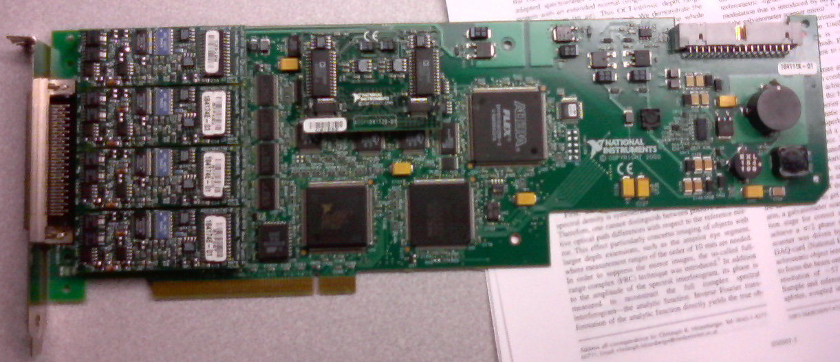
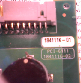
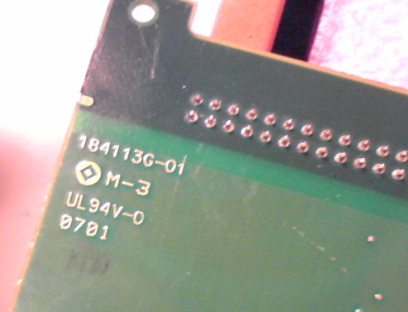
Based on the images below, what a card 6110 6111? Could he just scored, in which case the card is probably damaged?
It looks a little dfferent PCI-6111 cards available to us, but perhaps that is a previous model (it had been built, it seems, in 2000).
Or might pose the problem with inputs and outputs that the PC does not correctly recognize it? If this is the case, is there an easy solution (in relative terms) of the problem, sending to OR for repairs?
Thank you for reading.
Filipp,
Where did you got this card? It is a very strange problem. 184111 K-01 part number is for a 6110. The part number 184111 G-02 is for a 6111. The jury is without a doubt a 6110 as you can see the 2 of the 6111 4 chips on the left hand side related to the 4 channels of the 6110 vs. So I recommend you all what's wrong with that you send it back in OR for repair. You can give me a call at 1-866-275-6964 SEO SR #: 1436085 and I can help you through the process of RMA from here.
Tags: NI Hardware
Similar Questions
-
Would it not correct to say that the PCI-6110 can be set to 'redeclenchables' but the PXI-6115 module cannot use this property? If Yes, where is it documented the series cards can do trigger? For example, is it possible to configure the trigger on the PXI-6124?
Hi Joel_Neptune,
The PCI-6110 and other materials as the PXI-6115 S series and SMU-6124 do not natively support NOR-DAQmx analog input alarm. However, you can use one of the generalist counters/timers of the Council to generate a reenclenchees pulse train, then use this as the sample clock pulse train. This transportation example shows how:
LabVIEW\examples\DAQmx\Synchronization\Multi-Function.llb\Multi-Function-Ctr Retrigg Pulse Train generation for the Clock.vi sample
In addition, the new material of the simultaneous sampling X series are supported trigger analog input without using a separate task of counters/timers.
Brad
-
How to calibrate the PCI-6110 with NOR-DAQmx
Hello
I am a new user of the PCI-6110 Council tries to run the calibration using LabVIEW procedure. I look at the document "Calibration" on the page of the manuals for the Board of Directors,
http://sine.NI.com/NIPs/nisearchservlet?nistype=psrelcon&NID=11888&lang=us&q=FQL: 28locale % 3Aen % 29 + AND + % 28phwebnt % 3 A 1081 + OR + phwebnt % 3 A 7075% 29 + AND + 28nicontenttype % 3Aproductmanual % 29 + AND + % 28docstatus % 3Acurrent % 29% 20RANK % 20nilangs: en & title = NOR + PCI-6110 + manual
One of the first steps in the document is to call the AI_Configure command to set the input mode, beach, etc. I'm using LabVIEW 8.5 with the NOR-DAQmx software, and I can not find the command (which, in LabVIEW, seems to be "AI Config.vi") anywhere. The calibration paper was written in 2003, and I gather from Google searches (please, correct me if wrong) that this command is actually a part of NOR-DAQ traditional, who was replaced by driver OR DAQmx.
My question is this: what is the equivalent to AI_Configure command in the latest software? Is it perhaps a subsequent document describing how to calibrate using NOR-DAQmx?
Thanks much for any help.
Tom McLaughlin
Hi Tom,
The calibration Procedure series B, E, M, S, which is also linked from this page, describes how to calibrate the PCI-6110 with NOR-DAQmx.
Brad
-
Minimum width of the PCI 6110 AI signal
Hello
I have a fundamental question on channel PCI 6110 AI. What is the sample and hold time of the ADC used inside the map? Or how much time I have to keep my constant input signal for the true conversion of data.
Thank you very much in advance for your help.
TOROs
Hi TOROs,
You can find details on the ADC of 6110 here.
I hope this helps!
Bye,.
Licia
-
PCI-6110 to change analog input range
The analog signal I want to measure is 24 volts and the maximum PCI 6110 is Volt.However 42, analog inputs that appear in the device under device NOR-DAQ traditional (old) configuration is 10 volts (single selection). I'm using LabView 7.1, DAQmx 8.6 and there is no function for allowed me to modify and change the analog device input range (Please find the print screen of the attachment). Can I know how can I change the analog inputs range?
I think that's what you're looking for:
S how to set up a data acquisition card series for the entry level so it does not Clip?
You must set up an appropriate gain so that the other ranges of voltage is displayed.
In addition, you can post on the forum instead of Labview data acquisition in the future, because the chances are that you will get better/faster responses there

Good luck!
-
I am trying to take data continuously from 4 channels maximum 5Msamples per second and writes at the same time as the data on the drive using the TDMS writer. I use daqmx LabVIEW tools to read and write data. I get failry good flow, but it is not completely continuous.
1 is it possible in Labview?
2. is it possible with NIScope? NIScope is at all related to labview?
Thank you
Ben.
I'm not an expert DAQmx, but it is a fairly common use case covered by the API. You can configure DAQmx so that when the data are collected, it is written as efficiently on the disk. You can do it for a continuous data stream. You can find an example of this here (and more examples using the LabVIEW example Locator: Help-> find examples...):
\examples\DAQmx\Analog Input\Voltage - Input.vi continues This VI uses the data at the level, so you will want to choose not adjusted I16 data for the type of output to the maximum speed.
Alternatively, you can use a producer/consumer architecture, acquire data in a loop and it continuously to the PDM in another. It is essentially this as the example above, but much easier and more quickly, because it involves fewer copies of data.
Good luck!
-
PCI-6110 - calculated resolution RMS
We have a requirement for the resolution of measurement of voltage AC RMS. I am in a position a repetitive alternating signal with 512 samples on 1 cycle using the range full scale. I then calculate the value of these data. What is the effective resolution of the RMS measurement? Should not 512, 12-bit samples (signal varies for each sample) produce a measure of 12-bit resolution? How can calculate the actual resolution of bit RMS?
I don't see how it takes into account the benefits obtained with various LSB errors between samples.
The best I can determine via Google is the increase of the resolution for a simple average is the square root of the number of samples. So 512 samples would result in improved time 22.6 (adds 4.5 bits). The improvement of a quadratic average is probably different (less), but my test here with real hardware is in this stadium. Google also revealed that some applications intentionally add a small amount of random noise, resulting in a dramatic improvement in the calculation the resolution.
-
Multiple PCI-61XX cards can be connected to sample at the same time? If so, how?
Our plans include a variety of experiences that involve the acquisition and use of cards PCI-6110, 6111-PCI and PCI-6115 for the acquisition of analog signals. Is is possible to combine two or more of these cards so that they sampled simultaneously and thus increase our number of simultaneously sampled analog input channels? If so, what are the physical connections, and how the software is configured to control simultaneous sampling? Thank you.
The DAQmx driver that makes it really easy for series S, DSA boards and X series (but mutually exclusive, you can't mix and match the 3 ranges). You need all the cards in a PXI chassis or, as in your case, a RTSI cable connected to all the advice and the cable set in MAX. To configure the cable in MAX, right-click on "Devices and Interfaces", select «Create a new...» "and choose"RTSI Cable. For each device in the RTSI cable is connected to, right-click in MAX, choose 'Properties' and set the cable in the tab 'Configuration RTSI.
Once it's all installation its as simple as adding all the channels to a single task. For example, your physical channel channel could be ' Dev1 / ai0:3, Dev2 / ai0:1, Dev3 / ai0:3 "for a 6110, 6111 and 6115.»
-
How to delay and trigger output for redeclenchables DAQ
I make redeclenchables data acquisition based on the technique described here and that my departure point couple year I used joint comes with LabVIEW example.
What I realize now is also already done that I need to delay the recognized outbreak and output as a trigger for any other device signal.
How to make a simple diagram:
Trigger is recognized-> DAQ [which works perfect already more than a year]
-> wait 100ms-> exit the trigger [to be added]Using Windows XP edition family, NI PCI 6110
I thank you in advance to anyone interested
-
DAQmxRegisterDoneEvent does not not in Win64, but working in Win32
Dear all,
We have a problem with DAQmxRegisterDoneEvent on 64-bit Windows 7, but not Windows 7 32 bit.
We have two versions of our application, one for Win32 for Win64 - the same code, just recompile the appropriate target. The code of NIDAQmx control a PCI - 6110S.
In both cases, we ask:
DAQmxCreateTask
DAQmxCreateAOVoltageChan
DAQmxCfgSampClkTiming with DAQmx_Val_FiniteSamps
DAQmxRegisterDoneEvent with the address of our reminder
The callback registered with DAQmxRegisterSignalEvent should fire once a fixed number of samples is issued on the analog channels. He doesn't under Win32 but Win64. It is never called.
It is unlikely to be a problem with recall statement (Nothing breaks down) or a performance problem (too many reminders), as the recall should happen every ~ 0.3 s.
The Win64 config is Win7 Pro OR-DAQmx 9.5.1
Has anyone seen this?
Thank you all.
My mistake.
DAQmxRegisterDoneEvent works fine in Win32 and Win64.
The bug has been introduced by declaring bad DAQmxCfgSampClkTiming in the 64-bit program. The task triggered never gone wrong a done event because the count sample in DAQmxRegisterDoneEvent parameter.
-
I use a counter that is generated by a PCI-6110 to switch a relay to solid state that enables or disables a heating unit. I update the duty cycle based on the output of a PID controller (0 - 100 output of PID VI gets scaled to a cycle of 0.001 to 0.99). The question is after two iterations, the written property node is no longer the output of PID on the scale to the task and it seems 0 as the default value.
Many meter generation examples use event structures to detect a change in the duty cycle and pass that to the task. But structures event detect changes in values if the value is written in a local variable and not typed in a CNC? I feel that the answer should be 'Yes'... but in the case I tested it seems to be 'no '.
Don't adjust the precision of a digital indicator / control limits the number of significant digits does a calculation? I would limit my duty cycle to 2 decimal places - i.e. 0.3342 and 0,3313 the two would be 0.33. In this way the cycle is not unnecessarily updated.
The temperature is read by a PCI-4351... which may arise under? blocks if you have not installed the drivers.
arcranda wrote:
Many meter generation examples use event structures to detect a change in the duty cycle and pass that to the task. But structures event detect changes in values if the value is written in a local variable and not typed in a digital control?.
To have a triggered event when a value is changed programmatically, create a Value property node (signaling) and the new value of wire to it. This will trigger a change of value for this variable event.
arcranda wrote:
Don't adjust the precision of a digital indicator / control limits the number of significant digits does a calculation? I would limit my duty cycle to 2 decimal places - i.e. 0.3342 and 0,3313 the two would be 0.33. In this way the cycle is not unnecessarily updated.
.
Changing the properties of display to show only 2 decimal places does not change the numeric value stored in memory. You would have to round up the digital to two decimal places. To do this is to multiply the number by 100, change of an integer (this will lose the remaining decimals), then divide the result by 100 to get again the two decimal places. When changing to an integer, you will need to round to the nearest integer to make 0.3299 0.33.
-
Work PCI6110 Board P/N 184111 L - 01 Will NEITHER-DAQ 6.9.3 revision L
Hello:
I have an older version of Labview and I wonder if a PCI-6110 card with part number 184111 L-01 would work with NOR-DAQ traditional such as NOR-DAQ 6.9.3?
Thank you, David
Hi David,
Yes, it looks like this should be possible. The 6.9.3, hereOR-DAQ readme file, mention of the PCI-6110 and it should be compatible with this version.
-
Hello
I have a small question on an example of clock by RTSI source.
In my configuration, two PCI cards (PCI-6602 (dev2) and PCI-6110 (dev1)) are connected by a RTSI cable.
I would like to build a clock on 6110 source sample and use it on 6602 counting external impulses of entry.
In the MAX test Panel, I checked that a meter was reading of external signals.
However, the vi attached do not work, and the whole County, and then give an error of 200284.
Could you tell me what is the problem?
I guess that something is not right on the clock signal routing. I have to use DAXmx connect terminals vi instead of external signal?
How can I check that both devices are connected through a RTSI cable?
I recorded the cable and connected devices on MAX with no problems. Is this enough?
Thank you for your comments and kind suggesion.
Several things briefly:
- Must match the orientation of the RTSI cable. Connectors are generally indexed to ensure this, but if you use a cable in water House, just keep it flat between the boards.
- The code you posted attempts to use the time base internal 20 MHz as a sample clock. That will not work for several reasons, and the fact that you try suggests you may have a poor understanding of the functioning of the meter. You do * not * need to "sample" at a pace high in order to catch the digital transitions. The meter circuit manages everything in the material. What you "sample" in a task of counter is a County registry value. Digital TTL edges which are worth little matter how many times you "sample" it increases.
- I suspect you want to * account * cycles of the clock of the signal of your 6110, be it a train of pulses counter or a sample clock based on the tasks.
- I am writing an example that does without buffer sampling clocked by the software, to approximately 10 Hz. Dev2 uses to generate a pulse of 1000 Hz and uses Dev1 train to interrogate the County registry value in a loop. It is simple from the code you posted to help unravel the special problems of routing RTSI config problems. Start using something simple like this to see if DAQmx succeeds routing signals through RTSI.
-Kevin P
-
the use of two meters: one for the generation of regenerable impulses, one as a counter
I'm new on use the counters. I use an NI PCI-6110 multifunction data acquisition card. I want to count a digital input (on the connector of the PFI 2) pulse and also using the entrance to trigger another counter to generate impulses. So I configured the first counter (task 1) to generate digital pulses with PFI2 as a source of relaxation and redeclenchables award; and set up the other counter (task 2) to count the number of edges of the digital signal with.... But after the two tasks began, the first task was an error 50103 (or the possible reasons: NI Platform Services: the specified resource is reserved.) The operation could not be performed as indicated.) The block diagram is attached. Thank you.
Your Board uses very-old-in-electronic-standards-DAQ - STC a smart meter that requires a little secretly * two * counters work together to make a finite pulse train. He is not actually secret if you read the right parts to the right documentation, but it's not hard to miss if you are unsure you should look. It has been a while since I've done a lot with these counters, but I have this nagging thought that they may not support redeclenchables finishes pulse train generation at all. I would caution you to at least check this.
In any case, it is the reason for the error. The finite impulse generation task uses only the counter that you specify, but there was also this one to help. A couple of new generations of smart meter (NOR-TIO, DAQ-STC2) continues to have this limitation, but the * more * recent it is no longer made.
X series boards use the chip "NOR-STC3" that give you 4 programmable counters by the user instead of 2 * AND * everyone can generate pulse trains finish without using a help desk. You may want a pair of them upward with your 6110, assuming that you need simultaneous sampling analog 6110's capabilities.
-Kevin P
-
synchronized analog output - two cards
Hello everyone! I ve a little, or big problem - I want to generate three different waveforms (for example three signals of sine @ 10, 100 and 500 Hz)-both a PCI-6110 and the other a card PCI-6711. Is it possible to generate only one of them clocked at some point so that I can just connect my waveforms generated with the channel write function? If it is not possible to imagine a method (simple) to solve the problem?
Thank you!
Michael
Any idea?
Maybe you are looking for
-
How can I specify a label when I compose a new email?
To assign a label to a new e-mail message, I have to dial the msg and then send it. SO, I have to search for the message in the SENT MESSAGES and assign the label. It's too many steps. I would be able to establish a label while composing the text of
-
How to format a cell to calculate the distance based on names of cities in the other two cells
I am using 3.6.1 numbers to display distances in Miles or Km in column 3 based on the names of the cities in columns 1 and 2 For example: "Boston' appears in the cell"A1"and"New York"in cell"B1. " I would like that the cell "C1" then automatically r
-
Why the JRE is needed? [I uninstalled temporarily and FF366 still working]
Why the JRE is needed? I uninstalled temporarily and FF366 still works.
-
test panels failed to max4.5 on usb6008
Hi fellow users or, I'm looking to test a niusb-6008, using the window of test on the max4.5 software nothing works panels. the installed nidaqmx is version 8.8. I haven't bought the opportunity usb6008 so no installation cd. I downloaded the nidaqmx
-
BlackBerry Smartphones flashing led for new messages
My BB is set to Flash for new messages, but it does not work like that.