Minimum width of the PCI 6110 AI signal
Hello
I have a fundamental question on channel PCI 6110 AI. What is the sample and hold time of the ADC used inside the map? Or how much time I have to keep my constant input signal for the true conversion of data.
Thank you very much in advance for your help.
TOROs
Hi TOROs,
You can find details on the ADC of 6110 here.
I hope this helps!
Bye,.
Licia
Tags: NI Software
Similar Questions
-
Would it not correct to say that the PCI-6110 can be set to 'redeclenchables' but the PXI-6115 module cannot use this property? If Yes, where is it documented the series cards can do trigger? For example, is it possible to configure the trigger on the PXI-6124?
Hi Joel_Neptune,
The PCI-6110 and other materials as the PXI-6115 S series and SMU-6124 do not natively support NOR-DAQmx analog input alarm. However, you can use one of the generalist counters/timers of the Council to generate a reenclenchees pulse train, then use this as the sample clock pulse train. This transportation example shows how:
LabVIEW\examples\DAQmx\Synchronization\Multi-Function.llb\Multi-Function-Ctr Retrigg Pulse Train generation for the Clock.vi sample
In addition, the new material of the simultaneous sampling X series are supported trigger analog input without using a separate task of counters/timers.
Brad
-
How to calibrate the PCI-6110 with NOR-DAQmx
Hello
I am a new user of the PCI-6110 Council tries to run the calibration using LabVIEW procedure. I look at the document "Calibration" on the page of the manuals for the Board of Directors,
http://sine.NI.com/NIPs/nisearchservlet?nistype=psrelcon&NID=11888&lang=us&q=FQL: 28locale % 3Aen % 29 + AND + % 28phwebnt % 3 A 1081 + OR + phwebnt % 3 A 7075% 29 + AND + 28nicontenttype % 3Aproductmanual % 29 + AND + % 28docstatus % 3Acurrent % 29% 20RANK % 20nilangs: en & title = NOR + PCI-6110 + manual
One of the first steps in the document is to call the AI_Configure command to set the input mode, beach, etc. I'm using LabVIEW 8.5 with the NOR-DAQmx software, and I can not find the command (which, in LabVIEW, seems to be "AI Config.vi") anywhere. The calibration paper was written in 2003, and I gather from Google searches (please, correct me if wrong) that this command is actually a part of NOR-DAQ traditional, who was replaced by driver OR DAQmx.
My question is this: what is the equivalent to AI_Configure command in the latest software? Is it perhaps a subsequent document describing how to calibrate using NOR-DAQmx?
Thanks much for any help.
Tom McLaughlin
Hi Tom,
The calibration Procedure series B, E, M, S, which is also linked from this page, describes how to calibrate the PCI-6110 with NOR-DAQmx.
Brad
-
How to set a minimum size of the 'location' box in the toolbars?
I reorganized my toolbars by merging the location and the tab bar. I have the location on the left side and tabs * following *, like this:
[/ tab\/tab\/tab\ (<) (>) [LOCATION]]
Unfortunately, when the number of tabs increases, the location box becomes so weak that I can't even see the url of the site that I am...
Is it possible to force a minimum width of the location? I couldn't find a setting in all: config for it (I guess this would be a browser.urlbar of setting)
You can't do it for about: config
If you are really interested, take a look at http://userstyles.org/styles/45794
-
Increase the width of the label of button component Radio
Hi guys,.
I tried to find a way to increase the width of the Radio button component label I use in my Quiz - I have some long questions which are not fully visible in the label box, and he's hiding, how to extend the width of the label, so that she can receive.
I tried Multiline and Word Wrap in property textfield but its not getting my anywhere.
Here is what I currently use?
RB6. Label.Multiline = true;
RB6. TextField.wordWrap = true;
RB6. TextField.Width = 352;
But nothing happens, please help
I normally give up using the radio button label and just use a textfield that is adjacent to it, reducing to the minimum width of the component so that the area of the button.
-
How to change the configuration of the BIOS with NO SIGNAL - to accept the new card PCI - ex
Compaq Presario SR2030NX
Product #RJ036AA
S/N {removed privacy}
MB: ASUS A8M2N - LA
Bought: October 2006
OS: Windows XP Media Center 05
New graphics card: MSI N210-D512D2 graphics card GeForce 210-512 MB, DDR2, PCI-Express 2.0 (x 16), 1 x DVI, 1 x VGA, DirectX 10.1, mono-emplacement
New: 480w PSU
ERROR: NO SIGNAL on monitor and can not reset the BIOS to accept the new video card in the PCI slot
PROBLEM: The user reports the monitor suddenly became white with blue lines finally erased. On start-up, the screen shows "No Signal" then turns off.
Troubleshooting has included:
Fixing monitor with its cable to another PC - monitor work
Fixing working monitor and cable to the PC - No Signal
There is no boot beeps, fans, lamps, not work cable defeated, no video. I concluded the embedded video component failed.
Installed the new video PCI - ex card and new power supply 480w and still get NO SIGNAL. New video card specifications called for a minimum 350w power supply. The fan on the new video card PCI - ex works. Search on the HP Support pages indicates that the BIOS should be modified to change the type of PCI slot type in-flight video. Makes perfect sense to me, sounds like it might work.
How to reset the BIOS when you do not see what you are doing?
I have moved the jumpers to reset the CMOS, but cannot tell if it worked or not. I tried a couple blind BIOS resets, but I could do this for months.
If I could determine the Version of the BIOS, I might be able to blindly to reset the BIOS. The Compaq Options of Menu and "BIOS Setup Utility information" web page provides instructions for BIOS version 6 or less and version 7 and greater - menus and access steps are very different.
QUESTIONS: How to determine the version of the BIOS. Which key I hit to access the BIOS (F1, F10, esc, Del)? Which menu I followed to reset the type of video, so how can I save and exit?
Thanks for any help
GJBThank you Paul,.
I didn't know that it was just a function of Regedit - piece of cake.
-
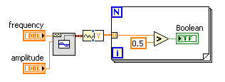
With the help of modulated signal pulse width (square wave) to control when a signal is enabled or disable
Hello all
I am using a modulated signal to labview created pulse width (square wave) to control when a signal is activated or not.
Here is my logic and a concrete example:
(1) the wave source signal is continuous
(2) use a PWM (square wave) created in labview to control when the signal is enabled or disabled
(3) if the PWM (amplitude) signal is superior to 0 play signal PWM is not greater than 0 do not play signal.I use actually this to the sequence step / pulse several distinct magnetic coils using my audio card (which has several channels of audio output), I have a signal in labview played constantly. As to compare it to the PWM (square wave) which controls whether or not the signal is played on each separate channel. That way I can control which coil is on and offshore and in what order they are activated.
I couldn't find an edge detection for a square wave created in labview, so I tried the limits, but it doesn't seem to work unless I change the phase manually and it only goes 1-1. I'm just trying to compare the PWM (edges of the square wave) already created by labview / play a signal if the pulse is greater than 0 and it shuts off the signal, if she is less than 0.
Should I do this another way
TIA
A waveform contains an array of values. You must check every value and respond accordingly:
-
Manchester in transmission/reception of signals using the digital output of the PCI-6224
How a manchester signal can be sent and received using the OID of the pci card 6224?
I want to create a signal NRZ manchester on a digital output channel and then have the possibility to receive and interpret the same type of signal on a digital input channel.
Any help would be greatly appreciated.
Hi VJohnson,
You might find this post of discussion forum useful.
Looks like LabVIEW has not Manchester coding/decoding built, but do able in your VI by replacing all the elements with the corresponding elements of two and using double the speed of transmission as your clock frequency.
Thank you
Scott M.
-
How can I measure the voltage of a signal?
Well!
I'm trying to read the voltage of a signal using acquisition data PCI-6229 card.i am giving the signal as an input to the DAQ card and try to read the voltage level. The range of my signal is 4.8 ~ 5.5 VDC but the results are not accurate, such as measured with DMM. My code is as follows:
1.i m using DAQmx create channel to create an analog input channel
2. then a sample clock with finite samples, sampels by channel and set the rate of iteratively
3. then I start the task
4. analog playback 1 DBL AK1 N sample d
Pressure readings I am differs widely that the actual.e.g a signal measured with DMM is 5v but when applied to the DAQ hardware and measured gives 6v.also I have to define minimum values and maximum in VI... If I put 4 to 5 maximum and minimum to measure a 5vDC signal it gives good result. , but if I change the maximum setting to 6v then it gives me results.also bad behavior is different for different signals for example when I measure a 6.5 VDC to signal that it shows me the voltage as 7.3V...
Photo of my code of VI is attached... Please answer... or give me another code that works fine at the voltage of a signal reading.
-
PCI-6110 to change analog input range
The analog signal I want to measure is 24 volts and the maximum PCI 6110 is Volt.However 42, analog inputs that appear in the device under device NOR-DAQ traditional (old) configuration is 10 volts (single selection). I'm using LabView 7.1, DAQmx 8.6 and there is no function for allowed me to modify and change the analog device input range (Please find the print screen of the attachment). Can I know how can I change the analog inputs range?
I think that's what you're looking for:
S how to set up a data acquisition card series for the entry level so it does not Clip?
You must set up an appropriate gain so that the other ranges of voltage is displayed.
In addition, you can post on the forum instead of Labview data acquisition in the future, because the chances are that you will get better/faster responses there

Good luck!
-
Years, I found code or an addon that allowed me to change the minimum width of a window of firefox. I've searched and searched but I can't find it again. I think that I did by adding the code somewhere but just can't remember or find. So, how can I change the minimum window width in Firefox?
The file type of the file is OK (Cascading Style Sheet), but the name is wrong and must be userChrome.css with a capital 'C'.
You must also create a chrome folder (note the tiny chrome in this case) and move the userChrome.css file in this folder.- C:\Users\ < user > \AppData\Roaming\Mozilla\Firefox\Profiles\ < profile > \chrome\userChrome.CSS
-
38.2.0 Linux Thunderbird does not width of the main window is normally paramèters
Last update prevents the resizing to a width that corresponds to the main Thunderbird window screen. The minimum width seems to be limited to an abnormally high value, which means that it is impossible to get a normal screen. The width can be increased without problem.
After further investigation, I found the cause of the problem.
It was the FoxClocks addon v 4.0.2. v v 3.4.14.1 the previous works very well and allows the main Thunderbird window to be resized normally; v4.0.2 doesn't.
-
Weird waveform using the PCI-5922
Hello
I'm having some difficulty with PCI-5922.
Rather than see a sinusoidal signal (generated by the PCI-5421), I see the forms attached wave, MAX and configured niScope EX Acquisition.vi
Sometimes he would turn to show a normal sine wave, often times it expires.
What could be a problem?
Thank you
Fomin
It's weird.
Could you give more details about your Setup?
(1) what is your operating system?
(2) what are the versions of NOR-SCOPE and NOR-FGEN you?
(3) you have another source of signals to test so that you can narrow down the problem to the digitizer or the generator?
(4) can we measure the same thing on the channel 0 and channel 1?
(5) what is expected of your sinusoidal signal amplitude?
(6) what is the result of executing a self-calibration on two of these cards?
-Jennifer O.
-
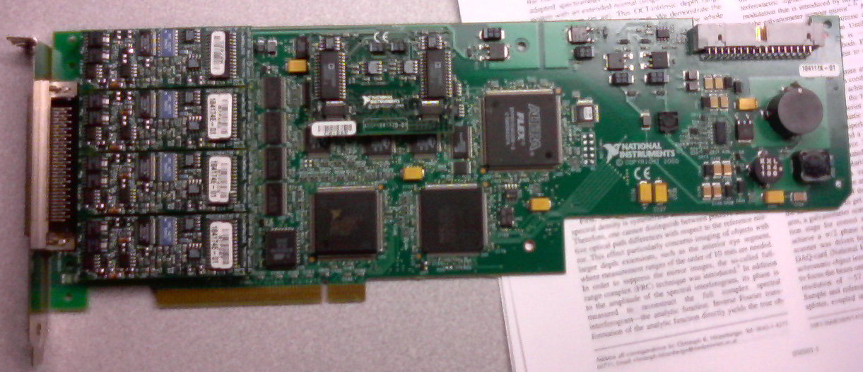
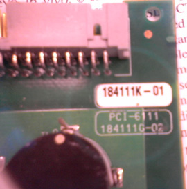
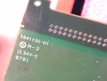
PCI-6111 is recognized as PCI-6110
I have a Board OR marked as PCI-6111, but when I inserted in a PC, it has been recognized as PCI-6110. Subsequently, none of the inputs or outputs work. The analog inputs still show a flat 10V line, while the exit is blocked to 500 mV. The card go through self-control, however fails self-calibration. Reset of the card does not resolve the problem.
Based on the images below, what a card 6110 6111? Could he just scored, in which case the card is probably damaged?
It looks a little dfferent PCI-6111 cards available to us, but perhaps that is a previous model (it had been built, it seems, in 2000).
Or might pose the problem with inputs and outputs that the PC does not correctly recognize it? If this is the case, is there an easy solution (in relative terms) of the problem, sending to OR for repairs?
Thank you for reading.
Filipp,
Where did you got this card? It is a very strange problem. 184111 K-01 part number is for a 6110. The part number 184111 G-02 is for a 6111. The jury is without a doubt a 6110 as you can see the 2 of the 6111 4 chips on the left hand side related to the 4 channels of the 6110 vs. So I recommend you all what's wrong with that you send it back in OR for repair. You can give me a call at 1-866-275-6964 SEO SR #: 1436085 and I can help you through the process of RMA from here.
-
The PCI-6052e does support I2C or SPI communication?
Currently, I am trying to build a data acquisition system to test, among other things, SPI and I2C devices verification of characteristics and surveys of behaviour without advertisement above the different temperatures. The DAQ card that I use is the PCI-6052e as well as the SCB-68. It has 8 ports DIO, but can someone tell me if it will support SPI or I2C? Another post in the forum indicated that it will not support 16-bit SPI, but for my application only 8 bit is necessary. I am not opposed to research in other materials DAQ, such as the USB-8451, but would like to see if the 6052e can do the job first. If she can't, then my next question would be; Can the 6052e and USB-8451 operate in parallel which allows me to use both analog and digital functionality? Thank you
If you will try little he hit then you might find these links useful:
Maybe you are looking for
-
How do I see wich version of Skype that I use?
In the past two days ive been receiving ads on "you have the latest version of Skype" and I don't really know how to find out
-
Fighting the problem of Audio Equalizer
So I got my laptop about 2 weeks ago, there is no problem, until about the last week when I opened the Manager tab LISTENING EXPERIENCE, and his Beats Audio was missing some things. But a few days before then, I was using it and it was working fine,
-
SBS2003 sbs2011 migration. Access denied on installing KB968930 powershell 2.0
Hi all, when trying to install KB968930, towards the end, and like its doing the up-to-date register I get an access denied error dialog box then it uninstalls. I tried as admin (run as) etc., log files that I include extracts, this seems to indicat
-
We have microsoft vista and cannot logon - received messages saying the password is not correct Admin and the other account.
-
where is all my programes. I was attacked by virus probebly
where is all my programes. I was attacked by virus probebly