PDM digit precision
I am drafting an instrument to record voltages in the meantime a 2420 Keithley microVolt and help TDMS to record their "real time". I just found out that the TDMS file has only 6 digits of precision, which is not enough, I need to at least 7. I looked but did not see a way to increase this, so here's my lateset dilemma.
I use LV2012 on a Mac, so I know THAT TDMS have just implimented this version, but does not remember no matter what arrangement of this type when I used the Windows LV PDM.
Thoughts?
Thank you
Vince
Cancel, I have found that the screen is only 6 digits of precision using the "PDM File Viewer", but opened with "reading TDMS" contains all the original precision.
Phew.
Vince
Tags: NI Software
Similar Questions
-
For some values of less than one my data sheets of often list an appalling number of digits for the measured value. Is there a way to limit the significant digits or the fractional part numbers shown on the card? The preference would be to two digits to the right of the decimal point. I have a VI that will do, but do not want to filter each reading.
Thank you
JVH
I know exactly what you're talking about, I had a lot of complaints about this operators wondering why a DMM measure out a few 10-digit precision.
TestStand 4.0, click on your stage of numerical limit. Click the tab limits, and then select the arrow next to the number Format drop-down list. Select custom, this opens the window of Digital Format. In here, you can select various options for the display of the data. See the attachment for a page where I put 2 digits of precision.
Thank you
Paul Holztrichter
-
Transfer the results of labview to teststand. How does it work?
Hello
Sometimes, despite the tact that my code LV module returns the data with precision - exactly - two significant digits, in the report of TS, I see sixteen-digit precision.
For example, the returned data (no not only displayed) by the module code is - 0.09 (DBL), but TS reports appear to me as - 0.0899999999999999.
Why is it like that?
Because you transfer a double-precision, floating-point number. The screen has nothing to do with the actual data.
-
Remove the scientific notation in report
I am calculating a number and put it in a box of comments on a report. It works very well, but one of the numbers has decided to display in scientific notation (1.52666667e - 3). The problem is that the comment box is not large enough to display scientific notation and gives no indication of more fit in the box. Instead, I see 1.52666 indication of the exhibitor. I had many prefer voir.001527 but I don't want to force a format of STR with "d.dddddd" because most of the numbers do not need this level of precision and I'd probably run into errors of numbers for example 12345 which does not fit in the 6 digit precision with forced comment box. If I can force it to scientific precision, it will probably be fine.
BTW: is there a certain number range where scientific notation is the default value? If I had known this range I could then force the format with the STR function to display as I want. for example IF x >-001 and x<.001 then="">
Or the other method would probably work for me.
Thank you
James
Okay - I see also tiara auto repeat to scientific notation decimal formatting. I guess what you could do is to check the number of decimal places, the value has and if it exceeds a certain number, format him with d.ddd.
Yes, something along the lines of: @@IIF (Len (valueToCheck)<10, valuetocheck,="" str(valuetocheck,="">
-
Quick questions of FPGA: Broadband Division vs Multiplication implementation (rounded)?
Hi all
I'm trying to implement a simple routine where I divide a FXP by number 7 to the FPGA. I wanted to use the broadband division, but it seems only to round to the nearest integer even if the output is capable of representing fractions. Otherwise, I can multiply my number by 1/7 using the proliferation of broadband and I get what I want. I'm not too familiar with arithmetic FXP. At least without understanding the problem, I have a solution that is to use the multiplication. I just want to know a little more. Can someone please shine an idea on why the division rounds even if he can manipulate fractions?
Thanks for your help
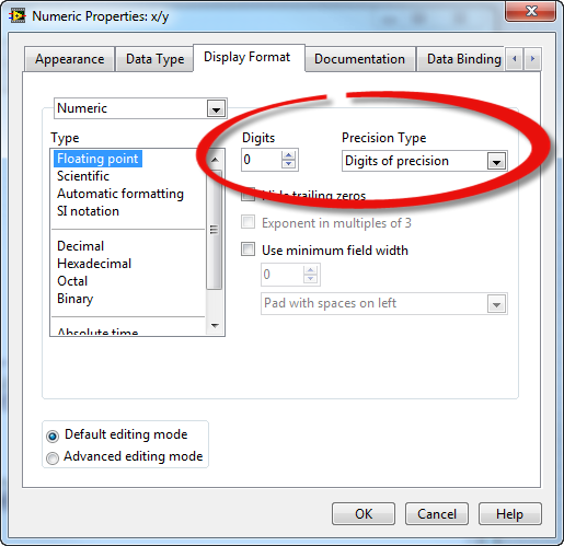
Somehow your obtained initial indicator set 0-digit precision for display formatting. This means that the data are indeed correct and there, but the text format of the on-screen display rounded to the whole number.
Any ideas how this parameter has changed?
-
Conversion of waveform (DBL) in table 1 of double d
HELO
I received samples of I and Q in waveform (LDM). Now I want to convert I and Q in complex form using Re / Im at the complex in the range complex. When I plugged the berries directly to the block, her gives me a connection error that says that
"You have connected two terminals of different types.
The type of the source's Waveform (DBL)
"The sink type is table 1 d of double (real 64 bit ~ 15 digit precision)"
How do I remove it?
I posted the document showing the problem.
Thanks in advance.
Use the appropriate function to extract the table 1 d from the type of waveform data. The data type of waveform consisting of a start time, a dt, and an array of values. To get the array of values that you want to use the function to get the elements of waveform in the waveform palette.
-
Some otherwise identical digital controls have white behind the numbers, other gray
On the attached screenshot, there are two Express Digital controls in the lower right corner. I did the replace operation to make sure that both are the same type of control, still it white behind the numbers and the other is grey behind the numbers.
I do not change the settings of these controls when I inserted the. I don't see anyway to change the background number without having to build a custom control.
The two controls appear in the same loop, are of type DBL, floating point with 2-digit precision.
Can someone tell me why these environments is different and if there is anything I can do about it?
You must choose the background color to change the background of the indicator. Note that there are two color boxes in the choice of colors. The upper left corner is for the text. Bottom right is for the background.
-
I just added a PXI-6653 to my chassis PXI-1011, in slot 2 and trying to replace the basket bottom 10 MHz native PXI_CLK10 with high precision an OCXO in the 6653. The goal is to provide a divided (by a factor of 2) reference clock, which has the accuracy of the OCXO. I run this in LV 7.1, NOR-MAX 4.5 etc..
The attached vi first connects OCXO to PXI_CLK10_IN, as a replacement for the native clock precisely this one. This part comes from "Clock.vi of road NO - SYNC"
Then, from 'NO-SYNC Generate DDS Signal, fracture and Route.vi' DDS takes the exact PXI_CLK10 of backplane and brings it to CLKOUT full frequency, but also a more bass that is divided by a factor of two to the EPR of PFI0.
The problem is that when I have the clock frequency to measure CLKOUT, there native backplane clock frequency (lack of precision), or approximately +/-4-5 ppm. I calibrated in fact my meter frequency by porting the OCXO out CLKOUT with the first vi, and it is calibrated to +/-0.5 ppm today.
My problem would be with the PXI-1011 chassis compatibility problems? I read in another thread on someone with a PXI-1033, which had put the switch S1. I can't find any S1 or other switches config on this chassis.
Someone at - he had similar experiences with the PXI-6653 and former chassis?
Thanks in advance for your comments,
Kurt
Peter,
Thanks for having a look at this. Yes, initially I brought OCXO to CLK_OUT, NOR - way Clock.vi SYNC and adjusted using the cal on the K & B (it has only 7-1/2 digit precision) for 10 MHz. This could serve as a basis to determine if I managed to replace the native frame PXI_CLK10 with the more precise OCXO.
The fact that the attached vi gives a PXI_CLK10 read only 10,00008 to CLK_OUT MHz gives to think that my chassis is unable to accept the OCXO on the PXI_CLK10_IN line. Referring to the manual for the chassis PXI-1011, under Section 1, 'Reference of system clock', missing the verbiage I should be able to do this. Other chassis, such as the "1000/B, ' 1042 and even the ' 1010 have verbiage that PXI_CLK10_IN line can be operated by an external source." So, I suspect that an upgrade of the chassis is in my future.
Thanks again for the reality check!
Kurt
-
PDM: Add DateTime vs PrecisionDateTime property
I'm back with another question about the API of PDM .NET.
What do you expect when you add a property to a DateTime value to a PDM file, then add another property with the same value converted to a value of PrecisionDateTime? The two must be kept as i64 + u64 bits according to the Structure of the TDMS File Format.
var someDate = new DateTime (635757120000000000L, DateTimeKind.Local);
using (var file = new TdmsFile (@"C:\Temp\ts.tdms ', TdmsFileOptions() ')) new

{

    file. AddProperty ("_ts0", TdmsPropertyDataType.DateTime, someDate);

    file. AddProperty ("_ts1", TdmsPropertyDataType.DateTime, PrecisionDateTime.FromDateTime (someDate));

}
In binary, the seconds total i64 are equal, but the part of fraction u64 to the first property is 0 x 0000800000000000.
Then when I read the first property, I get a difference in DateTime 76 ticks which is equal to 7.6 µs.
It's the 'precision' I get at the price of 128-bit?
Beste regards,
Jonas
HI jonas,.
Sorry it took awhile. We managed to do work and could reproduce the behavior. I forwarded your it.
Thank you for the information system.
Best,
Anna
-
Will I lose data conversion to double precision single-precision float?
Before you say Yes...
I use a crio unit in scan mode interface. Which returns the mode of scanning values in floating point double precision. Apparently I'm supposed to be able to choose between double precision fixed-point ("not calibrated") and ("calibrated") floating point data, but this feature seems to be exclusive to the fpga interface and is not available with the scan engine. The two data types are 64 bits per value, when it comes to the size on disk, anyway is still basically the same.
The system continuously records 13 channels of comma floating double-precision at 200 Hz. using the binary file write, I measured it is about 92 MB/hr on the disk. (more than 120 MB/hr with PDM and much more to write on the worksheet) In short, this 92 mb/hr rate is just too much data on the disk on this system.
The modules that I record since, 9236 9237 and 9215 c-series modules, have 24-bit a/d converters or less. Does this mean that I have not need 64-bit to represent the number and accuracy even?
Can I force/cast point values double-precision floating that I receive of the variables of e/s scan engine to the data type of a different, smaller, as a single-precision floating point and retain the same precision?
Nickerbocker wrote:
between noise and precision equipment, I doubt that it makes much difference.You can test it by looking at the difference between a DBL and converted to SGL DBL. But I support the Nickerbocker trick. I don't think it will make the difference
-
How to add a time stamp to a PDM file
I need to add a time stamp to my PDM file. Currently, I take an array of doubles, their conversion to a type of dynamic data, then send to tdms_write. I have to add a timestamp, but I can't find a way to do it. I also tried holding the timestamp, converting it into a doube, U64 and I64 and adding that to my table before the dynamic data conversion type, but when I lose precision. I need to have at least millisecond resolution. I know that I lose accuracy because the timestamp is two 64-bit values. top 64-bit are set to seconds since the epoch and lower 64 bit are fractions of a second. I would even send these two numbers divided in my happy tdms file and conversion at a later date, but can't seem to do it again. Any help would be appreciated.
The natural way would be using a waveform.
You can add your timestamp as two U64 (using cast to array U64) as properties of the channels as data t0.
Tone
-
Change the precision of the waveform data or daqmx read
Hi all
I am currently using daqmx read and write data to a PDM daughter. I would change the precision of the data if possible.
Any advice?
Thank you
Matt
It is important to get the right information in the data file. It is not a lot of overhead to limit your data with a specific precision if you as a table.
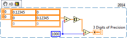
I don't know which is faster, the method of accuracy of the channels or this:
It took 1-2 ms per 1 million iterations.
-
The calculator program working if the second number is more than 1 digit.
I was setting up a calculator on labview, which works except for when I entered that a second number of the calculator does not have the correct value if the second number is more than 1 digit. I think it's down to the use of shift registers and result of the operation is forgotten when a key is pressed. I joined the program, if someone could confirm that this is the problem / suggest potential ways around this problem that would be a great help
RavensFan wrote:
Use default if Unwired. Several of your tunnels are defined in this way, including the orange wire (double-precision) where you store your first operand.
If you run an event where a wire is not connected through the tunnel will display by default (empty for string, double zero) and the shift register will then forget what he was originally in it.
I think you meant not to use the default value if Unwired? I think you have to tell him to use linked entry Tunnel--> Create and wire Unwired cases instead?
-
Defining the numbers of precision for TDMS logging
I can't find a way to put the figures of precision when the data connection to a PDM file. I jump to be able to reduce the file size by doing this. Any suggestions? Thanks, Cosimo
The data in a TDMS file is binary. If you cannot set the digits of precision. If you want to make smaller files, then mount your data to the singles instead of Doubles. You will have 1/2 the resolution, but use 1/2 the tracks on the disc.
-
Hi all
I just noticed this, but the precision (number of decimal digits) must be the same on a meter and its digital display? It does not make sense to me. If the meter not a - 10, 0, 10, why should we be forced to display as - 10,000, 0.000, 10,000 if we want 3-digit digital display below?
In other words, I want another precision on the meter itself and its digital display.
Am I missing something?
I strongly support your opinion! Until now I used to replace the digital meter a meter with an independent digital indicator exactly to reach another level of accuracy between them, but this can be problematic, because you can't forget one of the indicators was updated with strange effects obvious.
Please repost this in the exchange of ideas and I'm going to Bravo this idea immediately!

Maybe you are looking for
-
read in a labview complex binary file written in matlab and vice versa
Dear all. We use the attached funtion "write_complex_binary.m" in matlab to write complex numbers in a binary file. The format used is the IEEE floating point with big-endian byte order. And use the "read_complex_binary.m" function attached to read t
-
I have Windows Vista 32-bit 2.4Ghs HP M91501, I had to reformat due to the error of hard disk. After formatting the PC, I went online to play or surf the internet is slow. I move fast and Lupe moves. I tried to highlight something and it takes up to
-
Discovers all rights are used on the rights to file or server
We use Quest AD or have direct use on the server, I am trying to clean the server and assign groups instead of users connected directly to the server; instead of walking down, he threw all the files is a tool that you print or view with rights on the
-
Group to be installed on the VPN Client
We run IOS 8.2 (2). We configure VPN groups to authenticate locally to the ASA. We have about 10 different groups (marketing, engineering, accounting, technical support, etc.) that I need the installation which is no problem. My problem is that I h
-
No documentation for worm VPN clients. 5
Hello Why it seems that there is no documentation on the Cisco site for VPN clients past version 4.6? There are release notes, but no user guide. We recently bought an ASA, but the accompanying CD has an older version of client. Thank you -Steve