Precision digital multimeter
Hi all
I just noticed this, but the precision (number of decimal digits) must be the same on a meter and its digital display? It does not make sense to me. If the meter not a - 10, 0, 10, why should we be forced to display as - 10,000, 0.000, 10,000 if we want 3-digit digital display below?
In other words, I want another precision on the meter itself and its digital display.
Am I missing something?
I strongly support your opinion! Until now I used to replace the digital meter a meter with an independent digital indicator exactly to reach another level of accuracy between them, but this can be problematic, because you can't forget one of the indicators was updated with strange effects obvious.
Please repost this in the exchange of ideas and I'm going to Bravo this idea immediately!
Tags: NI Software
Similar Questions
-
Guides can be defined precisely digitally?
For example, I would put guides to 20 cm, 35.2 and 45.5 cm.
Can I do this digitally? It doesn't feel too precise when you zoom right/move, even with slam... digital positioning would make life much easier!
I'm in CS3.
Thank you
Andrew
Select each user guide and you can precisely define the value of X or Y for its position on the control panel.
-
Clear Image Zoom vs. Digital Zoom precision, what is the difference?
What is the difference between a clear picture of the HX300 and HX50 zoom I'm considering the purchase compared to the precision digital zoom of my current HX9v? It is just a marketing term, or is there a real difference? Is there a difference, what is it, and it translates into better image quality?
TIA
Here are the definitions of optical zoom, digital zoom of a clear picture and precision digital zoom. In short, for the zoom digital best picture quality clear picture has a data base of models, he may return to the and create new pixels for better image quality than the digital precision zoom which is basically just crop in.
Optical zoom: true zoom, using the optical quality remains the same and the full resolution of the camera can be used on the enlarged image.
Zoom digital picture: processor compares patterns found in adjacent pixels and creates new pixels to match the selected reasons, resulting in more realistic images and better
Digital precision zoom: enlarges all image sizes according to the zoom scale total about 64 x, including the optics x 16. Note, however, that the quality of the image degrades when the optical zoom scale is exceeded.
-
I'm rather new to LabVIEW, only used for about 1.5 weeks from this post, it means that I may be missing something pretty obvious due to ignorance, but is it possible to make my front to change as my changes of breakage due to the selection of the user to a certain case via the front panel?
The goal of the program is to make a simple layout for a user who uses the digital multimeter that the proposed code is designed for and I don't want tons of digital controllers and such clutter the screen that do not work with the function of the user uses to measure with.
Thanks in advance.

Yes.
Two ways: 1. use a tab control.
2. use of property nodes (Visible property).
The tab control is a bit easier on the block diagram, but if some controls should appear in many cases it is difficult to do. Property nodes take more space on the diagram but allows you the versatility to do almost everything you want.
Read the help files and look at a few examples.
Lynn
-
Hi there, people
I have an Apple AirPort Extreme Base Station (AEBS) model #A1034 without a power supply.
I have problems/disorders sourcing a compatible universal power adapter.
I tried using the following information: 5V DC/3 has (3000mA) / 15W. Amazon/Best Buy / Micro Center / Radio Shack / Wal - Mart / etc., NO SOAP!
I thought to go to the local Apple Store and ask about a supply of suitable replacement AEBS, but they would probably tell me to buy a new AEBS instead.
Perhaps a "most recent" AEBS diet would have comparable production?
I have a digital multimeter @ the loan...
My directions: iBook SE (PowerBook2, 2) with AirPort (802 11b) /OS X 10.4.11.
Any insight/input/info would be greatly appreciated
Thank you for your time, James
Works fine... but is not white... If it's important.
http://www.Amazon.com/UpBright®-adapter-T012A051-Airport-Extreme/dp/B00IPWMS46
Haven't tried this one:
http://www.Amazon.com/EPtech-adapter-T012A051-Airport-extreme/DP/B00XOHNR6K
-
very slow niswitch with signal connected (PXI-2535)
First time using a switching FET card, running base vi where I connect a line and two columns, and make a measure of resistance with a multimeter.
I found that with the digital multimeter connected, IE the applied signal, the switch may take more than 5 seconds to close. (Ohm DMM reading 26 ohms after 5 seconds, the 'debounce expectation' although all good reported vi)
If the DMM is not connected, sometimes instantaniously. (disconnect the DMM, perform the trigger, connect the DMM - instant closing)
Anyone experienced the same thing?
Found the problem.
Seems the FET card goes into protection mode if you do not connect the DMM - signal to the chassis GND.
After that, it worked fine.
-
Entered analog PCI 6251 not extent of tension of a mass flow controller
Hey,.
I have a data PCI 6251 M acquisition with a break in Council SCXI 1302.
I'm trying to measure a 0 - 5v analogue output voltage from a mass flow controller (check picture of PIN)
When I measured with a digital multimeter the voltage of the flow signal (PIN2) and common signal (PIN12) I get a stable right tension between 0 and 5v depending on the flow set up. I can control the amount of the charge by providing a data output set point PIN8 and common PIN12 of the 0 - 5V analog signal.
Now when I connect the signal flow PIN2 and on my DAQ signal common PIN12 AI and AIGND, I don't get readings on my labview VI of the AI. In addition the flow does not meet the setpoint voltage, it get stuck in a range of values no matter how I vary the OD 0 - 5V of data acquisition in setpoint PIN8 and PIN12 common signals.
I have to add that I tried different ports HAVE with results of sam, and I also tried to measure my supply voltage with my HAVE and all the good work.
It seems that the entry of AI affects the AO output voltages to my charge. What would cause this? That would be a problem of impedance adaptation?
Management or ideas are appreciated.
Thank you
Ali T.
Update for anyone that might interest you:
I not connected to the ground of the power of the mass of the signal of FJA FJA.
Once I did the acquisition of data reads all data as expected.
So it turns out not to be a problem of acquisition of data, OR at all, but a game of question for my part, as I suspect is the case with most of the problems.
Jeff Merci for your comments.
Ali T.
-
Currently, I am trying to log readings of DC voltage with an AA battery in an ASCII using LabVIEW 2009 of SingalExpress file and the USB-4065 digital multimeter (DMM). I have two stages:
(1) acquisition of Signal > voltage DC using DMM
-resolution 4.5 with 3.333333E the value-5 sampling period
2) save in ASCII
-The value to add to the file, delete the file after each race
Faster reading, I can get is a data point written in the ASCII file every eighth of a second.
Furthermore, I am new and software OR LabVIEW, the LabVIEW SignalExpress software I have is only for evaluation as it was included in the CD of the driver for the USB 4065 DMM.
- Max (30 000 samples per second) sampling rate is only achievable by a LabVIEW VI?
- Don't I have the wrong settings for DMM step?
- Is it because I haven't activated SignalExpress and am only using the evaluation version?
Thanks in advance for any help!

Hello Lukos,
You are assuming that you need access to lower level functions in order to obtain the higher sampling rates. In order to get these speeds, we need to disable some settings that are not accessible via Signal Express. You can create a VI and then use a step VI call in Signal Express to stay in the same environment.
Kind regards
-Travis E
-
Export the extent of DMM trigger
Hello
I would like to export the trigger Signal, which I receive on channel 0 of the scope to a DMM in a PXI system.
So far, the scope is what I want it to do (Acquisition of 1 Record with a length of 550000 at a sampling frequency of 50 kHz with a 1 s pre-trigger).
I would need to know the value of the DMM measurement in the scope of triggerevent. For this, I have inserted the signal.vi 'export' to the scope and set it to trigger reference and as terminal output that I chose 'the trigger PXI 0/RTSI0 line. The digital multimeter, I put the command Source for "TTL0", which should correspond to the line on which I'am export the Signal of the scope.
But it does not work. The DMM sends the value as soon as I start the vi (she does not wait for the Triggerevent). If I choose 'none' as a signal to export in the scope, the DMM waits until he goes into a timeout. Do I have to configure something differently, or do I have to use the vi TCIk?
Thanks for your contributions!
Pietro
-
Internal resistance on 2800 backplane?
I have a new switchblock 2800 OR 2811 A card that I connect via a Virginia Panel ITA. Before using the switches for my project, I was testing the switches and I found a behavior that I wasn't expecting. I have a 4072 digital multimeter connected to SwitchBlockDev5 c16 and c17. When I connect c16 and c17 through another line in the first attachment (c5 is the other line in this example) then I measure resistance of ~ 200 ohms (I expect something close to 0). When I cross the lines from the bottom of the basket and connect the DMM leads it as in the second setting (where the lines are connected on SwitchBlockDev6 c18) then I measure Mohm resistance ~ 168 (I expect something close to 0 or 200 ohms), if I pass the DMM wires on the second configuration then I get - 4.45 Mohms under my measure. Can someone explain what is happening and what the circuit looks like? Is there some kind of framework, I can do in the software that will give me my desired values when I do these DMM measures?
Thank you
Chall
Chapin,
The 200 ohms you receive is probably because you are using the cable "SH96F - 96M - RES. There are two cables NI SwitchBlock, a 'normal' and a cable with resistance of 100 ohms additional linked internally to the cable by column [two whole columns = 200 Ohms]. This additional resistance of 100 ohms is used to prevent the current overloads. If you use the cable "SH96F - 96M - RES ' and you want to read 0 Ohms, you need to replace the cable with the cable"SH96F - 96M"'normal '.
168 M Ohm resistance you measure is probably due to the missing safety lock Resistance on your test setup. If the resistance of safety lock is missing, connections between the relay in your support of 2800 cards will never connect.
-
Calibrate the NI 9265 cRIO module
Hi guys
I have a few output current modules NI 9265, analog and I would like to perform an external calibration using a digital multimeter to 8 1/2 available in the laboratory. I tried to do it using a MAX interface, but I discovered that it is not possbile because the analog module is installed in a cRio-9074 control. I don't have this controller and an EtherCat chassi to install modules. Is there another way to calibrate with DAQmx with the NI 9265 installed in the cRio control? Would it not possible in LabView?
Hey Lane,.
Unfortunately cRIO or EtherCat frame can be used with DAQmx since they do not belong to the data acquisition platform. Some (e.g., NI 9265) cSeries modules are supported by both platforms, but it can only be calibrated by a cDAQ platform.
If you check the manual for calibration for the NI 9265 (if you have not yet verified) you will see that it is recommended to use a cDAQ-9178, including a cDAQ chassis 8.
http://www.NI.com/PDF/manuals/372667b.PDF
If you really need an external calibration, please contact your local office of OR to get more information on calibration Services.
Best regards.
-
Why the digital multimeter (DMM) software does not work if the NI ELVISmx Instrument Launcher is?
Initially, I installed subsequently myDAQ NI 2015 that included the NI ELVISmx Instrument Launcher containing the DMM software. Other pieces of software work however, the DMM stalls immediately after starting with a NI Instruments loading bar.
I tried the repair option of software specifically for the NI ELVISmx driver and also tried wiping clean and reinstall fees. By receiving the same result.
-
Measure the voltage of strain gauge
I have connected my 9237 to a 9945. I use a 350 ohm strain gauge. I have the voltage set to 2, 5V Max is there a way to measure physically to be sure that it is 2.5V? Also, in my vi I use a DAQmx create function of the channel. I want to add another channel for this but can't see how to do it.
Thank you
HS
Hi, Harry, it's Paul with engineering Applications to the OR.
My first question is why you are wanting to physically measure the voltage?
If you are wondering how that tension may vary, it is limited by the maximum capacity of 150mW of your device, as explained here: http://digital.ni.com/public.nsf/allkb/7CBC67482CC9FB318625758C0048FF73?OpenDocument
If you want to continue to measure externally, you have a few options. You can use another DAQ hardware to measure the voltage, or you can use another external device, like a digital multimeter.
If you want to see in the excitement that is actually supplied LabVIEW code, you can use the node property DAQmx 'Value of real excitement'.
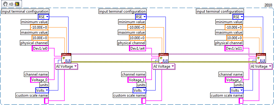
As far as playback of multiple channels, theres two ways you can go about it. If your channels are sequential and all have the same settings, then you can change your name of the physical channel to something like 'Dev1/ai0' to ' Dev1 / ai0:3: to specify the first 4 channels.» Alternatively, if you wanted to select non sequential channels, you can chain create channel set tasks, as long as they are of the same type of task (AI voltage, etc.) and the same device, as shown below.
Let us know if you have any other questions.
Kind regards
Paul
-
the entry on Tektroniks DMM4040 high impedance value
I use a Tektroniks DMM4040 with itself to record data of voltage. When the digital multimeter is used in manual mode, there is an option for a high (> 10 GOhm) input impedance during the measurement of the potential.
This option can be introduced on the market when the multimeter is controlled by SE?
Thanks in advance!
Marc
-
Switch Soft Front Panel, active device classified
I have a with PXI chassis modules, two switches PXI-2350. Using the Soft Front Panel switch, it seems that the names assigned to the list of active device (both 2350's in this case) are backward, what to expect. Is there a way to reassociate those names to the 2350's physics?
Thank you
Confustus,
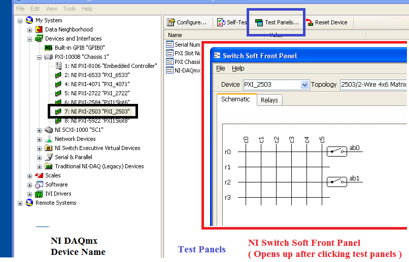
It's an interesting question that I've never seen before, your devices in a Soft Front Panel should be linked to features like labels in MAX. I was wondering, when you say "we can select using MAX, a road that connects the power supply to the digital multimeter using"Switch 1"(for example), and we can see the voltage reading show on the Soft Front Panel 4071 as planned", what you mean exactly? If you had to choose your hardware device, and then click test panels, the NI Soft Front Panel load switch. Are you saying that when you choose test panels and loading Switch Soft Front Panel of max works as expected, however the application outside opening MAX does not work?
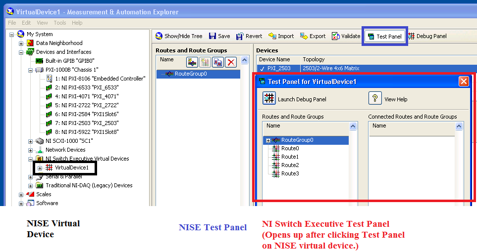
Or are you talking about the Test panels you open in NI Switch Executive? The test for NI Switch Executive panels refer on behalf of virtual device NI Switch Executive, not the DAQmx device name. If you had named the name of the NI Switch Executive virtual device in the same way, that could be part of the confusion of the problems that you see. See the images below:
NEITHER DAQmx Test selection panel that leads upward.
Test NI Switch Executive Panel allows this. If these names are similar, I can see how that might be confusing.
Maybe you are looking for
-
Problem with adding previously blocked contact.
I tried to add an old friend of my friends on Skype after believing have been they are blocked for a while. I emptied my blocked list and sought their username after asking them what it was, but the Skype directory could not find them. After about an
-
Updates hung to "16 of 16 installation" in Windows 7
Original title: Update hangs the system windows 7 Last night the system performed an automatic update for windows 7 and now the system is blocked, try to install the update 16 of 16. Nothing will stop it it or we can get the system in safe mode. Some
-
Smartband talk is disconnected and does not restore
1 week old and it comes up with 'Samrtband is disconnected, you may be off' is 8 inches away, restarted my z3 xperia and always the same, both fully charged.
-
HP ENVY 7640 e: MultiPage, scan to a file
Scanner will not allow several scans of page in a file of the glass. A checkbox exists in the advanced settings to create a separate for each analysis file, if it is enabled. However, if nothing is done there is no button ('+ ', 'Add', 'continue',
-
Icon email to blackBerry Smartphones
Hi all I have a little problem, I entered my user name and then send the e-mail settings and then the icon email popped up and I was happy with that. But suddenly he disappeared, but I receive my emails in the messages icon, but I want my e-mail back