PXI_CLK10
I just added a PXI-6653 to my chassis PXI-1011, in slot 2 and trying to replace the basket bottom 10 MHz native PXI_CLK10 with high precision an OCXO in the 6653. The goal is to provide a divided (by a factor of 2) reference clock, which has the accuracy of the OCXO. I run this in LV 7.1, NOR-MAX 4.5 etc..
The attached vi first connects OCXO to PXI_CLK10_IN, as a replacement for the native clock precisely this one. This part comes from "Clock.vi of road NO - SYNC"
Then, from 'NO-SYNC Generate DDS Signal, fracture and Route.vi' DDS takes the exact PXI_CLK10 of backplane and brings it to CLKOUT full frequency, but also a more bass that is divided by a factor of two to the EPR of PFI0.
The problem is that when I have the clock frequency to measure CLKOUT, there native backplane clock frequency (lack of precision), or approximately +/-4-5 ppm. I calibrated in fact my meter frequency by porting the OCXO out CLKOUT with the first vi, and it is calibrated to +/-0.5 ppm today.
My problem would be with the PXI-1011 chassis compatibility problems? I read in another thread on someone with a PXI-1033, which had put the switch S1. I can't find any S1 or other switches config on this chassis.
Someone at - he had similar experiences with the PXI-6653 and former chassis?
Thanks in advance for your comments,
Kurt
Peter,
Thanks for having a look at this. Yes, initially I brought OCXO to CLK_OUT, NOR - way Clock.vi SYNC and adjusted using the cal on the K & B (it has only 7-1/2 digit precision) for 10 MHz. This could serve as a basis to determine if I managed to replace the native frame PXI_CLK10 with the more precise OCXO.
The fact that the attached vi gives a PXI_CLK10 read only 10,00008 to CLK_OUT MHz gives to think that my chassis is unable to accept the OCXO on the PXI_CLK10_IN line. Referring to the manual for the chassis PXI-1011, under Section 1, 'Reference of system clock', missing the verbiage I should be able to do this. Other chassis, such as the "1000/B, ' 1042 and even the ' 1010 have verbiage that PXI_CLK10_IN line can be operated by an external source." So, I suspect that an upgrade of the chassis is in my future.
Thanks again for the reality check!
Kurt
Tags: NI Hardware
Similar Questions
-
Hello
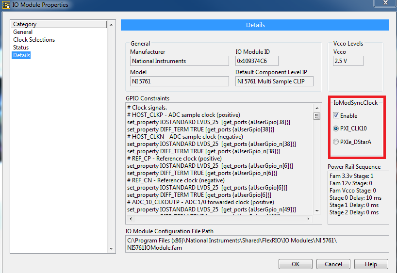
I want PLL select my 5761 to PXI_CLK10 by setting the sample clock signal. I use the adapter with an SMU-7965.
The Manual 5761 synchronization article leads me to believe that I can do this: "Reference, 10 MHz, external clock through IoModSyncClock."
The subject of several CLIP sample 5761 in aid of FlexRIO gives me the value to write, "select the sample clock, 3 = sample clock internal locked to an external reference clock through IoModSyncClock".
And
\examples\FlexRIO\IO Modules\NI 5761\NI 5761 Select\NI 5761 - clock Select.lvproj clock shows me how to set the source of the clock to "clock PLL on (IoModSyncClk). I'm missing how to get the PXI_CLK10 to IoModSyncClock.
There is an explicit note in table 4 of the Manual of 5782 indicating, "the VCO internal locks to PXI_CLK10 through IoModSyncClock, which is available only through the backplane of the SMU-796xR NI devices", when the clock is set to the internal clock PLL on (IoModSyncClock). Perhaps the same applies to the 5761 even if they seem to have different options for overclocking?
I don't want cable CLK10_OUT of the chassis at CLK IN on the 5761 (which seems silly). I don't want to use the API of Sync FlexRIO Instrument Development Library to PLL to backplane.
Thanks for any help,
Steve K
You set the IOModSyncClock line in the FAM Propties page on the category details. By default, the PXICLK10 is automatically routed to the IOModSyncClk line.
-
PXI_Clk10 can be found in PXI6115.
I have two PXI6115, and I want to sync them. I found an example of examples of NEITHER. He said that both PXI cards can be synced through sharing RefClk10. But I can't found this reference clock signal. Can you give me any suggestions? Thank you very much.
Frogreenmm,
Let me see if I can help clear up your confusion. First of all, PXI_Clk10 is a signal that is present only in the PXI chassis. PXI-6115 have a PLL to lock to the signal. However, as you said you have a PCI-6115 so this synchronization scheme is not available to you. To synchronize these devices, you must share the signals between devices through an interface. You mentioned that you have a RTSI cable, so it will be the best way to do it. To use RTSI with DAQmx, you will need to go to the measurement and Automation Explorer (MAX) and add RTSI cable as a DAQmx device. This DAQmx allows to know the presence of the RTSI cable and will also allow the driver to perform automatically routes between your devices using this interface. To add cable RTSI, go to MAX and expand devices and control of the Interface. NOR-DAQmx devices and choose create new DAQmx Device-> RTSI cable. The RTSI cable should then appear in your list of devices. Right-click on it and select 'Add the device to RTSI cable.' This is to add both of your PCI - 6115 s RTSI cable.
At this point, I guess you have physically connected the two devices with cable and now DAQmx knows in this regard. Now, we could use one of the many methods to synchronize the devices. We can share a master time base and start the détente between the two devices or we could share a clock sampling and a trigger of departure between the two devices. The example of delivery DAQmx titled 'Multi - Device Synch - Analog Input - Finite Acquisition.vi' is an example of how share a time base and trigger start (look at the case of block diagram ' E and S series share Master Timebase '). In this case, the two devices will share the time base of Dev1, and both devices will use the beginning of Dev1 trigger to begin their acquisition. As long as you added your cable RTSI for MAX and added your devices to the RTSI, DAQmx cable can take care of the details of routing of these signals. An important note about this approach is that you call start on the 'slave' (Dev2) 6115 before calling start on the 'master' (Dev1). It is so Dev2 is ready for the trigger start signal when Dev1 sends it.
You can use a very similar approach by a sample clock between the two devices sharing rather than share the main time base. Yet once again, I recommend that you also share a trigger to start and start the 'slave' device before starting the "master" unit
Hope this helps,
Dan -
NOR error-89136 property set DAQmx_RefClk_Src with value/PXI1Slot2/PXI_CLK10
Dear members of the forum OR,.
We have just received a chassis NI SMU-1073 with an SMU-6361 OR switched in PXI1Slot2 and a shielded connector BNC-2111. Aims to trigger two output signals to control a laser and a sound via Matlab Application.
Version of Matlab is 8.2.0.701 (R2013b) and data acquisition toolbox is 3.4. Installed is the 9.8.0 driver NOR-DAQmx. We followed the example of the tutorial on the web page of Matlab to generate output. The code establishes a connection with a device, it creates a session and adds an output channel. Once this is done, the session is started in the foreground, but it fails with the following error massage:
OR error-89136:
Specified route can not be satisfied, because the hardware does not support.
Property: DAQmx_RefClk_Src
Requested value: / PXI1Slot2/PXI_CLK10
Based on some forums, we checked the route tab of device in Explorer automation and PXI_CLK10 signal is almost yellow everywhere. Looks like he expects, as a reference, the PXI_CLK10 clock, but there is no direct route to it. On the other hand, there are PXIe_CLK100 that is green.
Question is how through Matlab interface based session one can set the reference clock signal? Or y at - it another way to solve this error? Maybe another type of configuration is necessary?
Tips, drivers, and solutions are welcome!
Thank you in advance!
see you soon,
go9kata
P.S.: the same question has been added three different times to Matlab support page, but there was no response to all the
http://www.MathWorks.de/matlabcentral/answers/107494-acquire-synchronized-data-using-PXIe-devices
http://www.MathWorks.de/matlabcentral/answers/37134-data-acquisition-from-NI-PXIe-1062Q
Hi all
the last questions are displayed also here and replied:
-
Jitter in response to signal generator of digital dashboard by using trigger nor tclk with digitizer
I've written a VI that uses NEITHER tclk to synchronize a generator (PXI-5422 named FGEN1) and a digitizer (PXI-5122 named DIGITIZER1). There is also a clock card TIMING3 generating a digital camera.
It seems that can probably be explained by the way TCLK to synchronize, but I don't understand all the details. Could someone help explain this to me?
You are right. NOR-TClk ensures that all synchronized devices start at almost at the same time, to the same sample clock, with timing very tight. Sometimes, the level of synchronization with the devices OR TClk-synchronized beats at the level of the synchronization of the instruments of some competitor channels in the same device. But this is not free, there are compromises and added additional jitter for trigger response time is one of them. Here is an attempt to explain why:
When you use NEITHER-TClk and send a trigger, the devices will respond to relax on the next cycle of the clock once made the trigger signal to the device. Let's say you have several devices all of them even configured with the same clock frequency. You block the signal of PXI_Clk10 using their PLL, so they drift out. But each unit's clock edge will be off, clock +-0.5 cycles. If you send a trigger to each of them, they will respond on the next clock cycle whenever it is, after the arrival of the relaxation to each device with different propagation times, whatever they may be. You get a single clock cycle of jitter on reaction of device to set it off.
When you use NEITHER-TClk, several things happen: all devices are locked on the PXI_Clk10 signal to eliminate drift. The device clocks are then adjusted to a period level secondary clock. Very very tight. Then a clock signal common, slower called TClk is produced inside the devices. All the generation of trigger are delayed to be sent to the next rising edge TClk, and all consumption trigger is delayed to be received at the next front descending TClk. This way you make sure that propagation delays don't mean one of the devices does not react to the trigger until the next clock cycle.
That's why you see jitter above the reaction time of relaxation. When you add devices with different clock settings, so the frequency of the TClk can be slower for a divisible frequency in the device clock frequencies everything is possible. This causes the trigger jitter of reaction time be even slower!
I hope this helps you understand what you see.
-
Override clock backplane PXI-1033 with clock OCXO PXI-6653
I need a a more accurate 19.2 MHz clock of a PXI-6653. Supposedly, it is possible to replace the background clock of basket with a clock of the PXI-6653 OCXO PXI-1033. It is not clear to me how to do this. NEITHER literature suggests I may have need of a few SW. Thank you!
OK, it seems to work now, thanks for the very useful comments. Someone suggetsed online (with a useful picture) to adjust the background rider of basket of 1033 'up' position... that opens the way for PXI_CLK10 - replacement of background clock of basket with the OCXO clock... Now I get what I was looking for, a (frequency) very accurate 19.2 MHz DDS clock.
-
Reference clock synchronization and clock of sampling (not LabView but Daqmx, Sync and C)
Well, I found an example that resemble what I wanted... in LabView: http://zone.ni.com/devzone/cda/tut/p/id/9308
Now the question is all about timing of the timestamps and sample:
Here is a list of ficelleStringString ficelleT of what I called...
DAQmxCreateTask
DAQmxCreateAIVoltageChan
DAQmxSetRefClkSrc (used NISYNC_VAL_CLK10 = "PXI_CLK10")
DAQmxRegisterEveryNSamplesEvent
niSync_init (used a PXI-6682)
niSync_SetAttributeViInt32 (used Terminal = NISYNC_VAL_PXISTAR0 and NISYNC_ATTR_1588_TIMESTAMP_BUF_SIZE = 3000)
niSync_CreateClock (used Terminal = NISYNC_VAL_PXISTAR0)
niSync_EnableTimeStampTrigger (used Terminal = NISYNC_VAL_PXISTAR0)
Now this list makes me able to create a timestamp every time the clock triggers a RISING edge...
Now how to synchronize these timestamps are useful for my sample? (I mean I need to sync my calendar with the PXI_CLK10 card) because for now prices will not match the sample rate.
ALSO... a little weird...
some of my cards will accept DAQmxSetRefClkSrc but others must use DAQmxSetMasterTimebaseSrc.
Now I can't use DAQmxSetMasterTimebaseSrc with PXI_CLK10... no idea why...
So, how did I would synchronize THESE cards...
Alright I could totally be wrogn with my approach, but I'm new with stuff of OR and using C isn't exactly the best documented piece of the NC.
Thanks in advance,
SEB
Thus,.
We have the same clock sampling for all of these devices, but we are not PLL'ing with the card of the S series, we cannot guarantee that they will all be in phase. However, given that all of these devices would be based on the same reference clock, we would not drift when we started the task. Would this work?
An alternative is to use the new X-Series card, which can also do a simultaneous sampling, but I don't know if it is feesible within your application.
-
[FlexRIO] Start-up to synchronize several clocks sample
Hello
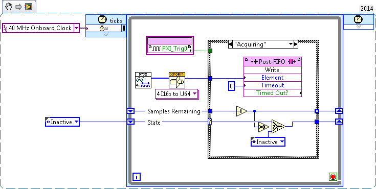
I tried before, two different (SMU-7962R + OR-5734) FlexRIO card reading in the '40 MHz Onboard Clock' or 'PXI_Clk10' areas of clock. Trigger has been achieved by simply looking for a rising edge on PXI_Trig0:
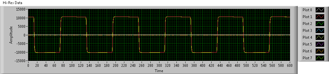
This produces seeds, but there has no inclination (or constantly tilt at least) between the two FlexRIOs - I sent a pulse train duplicated in the two cards, and the triggered-acquired waveforms were still at the stage:
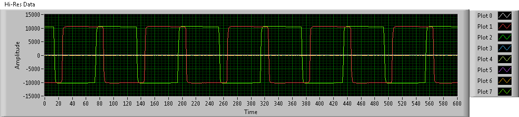
To avoid problems, I went to examples of clock (IO Module clock 0). Unfortunately, the clocks of the sample between the two FlexRIOs had nothing in common, so the acquired waveforms have been is out of phase. Worse still, the phase difference changes with each release:
Looking at the implementation of the library of the synchronization of the FIDL, the classic technique for synchronization of multiple cards FlexRIO seems to be built around synchronization master-slave (my observation is correct?). I was wondering: is there a way to simply share a sample clock shared between cards (like what the 40 MHz embedded clock was doing before), as described in http://www.ni.com/white-paper/11369/en/ ? (I think I understand the disadvantages associated with sample clock synchronization, but I'm willing to try for now).
Thanks in advance!
Hi JKSH,
Page 9 of the Manual 5734 described the different synchronized methods that can be used the 5734. You can synchronize either sample clock of each module to a clock available through your chassis backplane (for example, DStar_A) by allowing the IOModSynClk in 5734 properties (available the Details category) or use an external clock through the Clk port on the module. Activation of IOModSyncClk is probably the best approach and will lead by examples of clock on each module e/s being PLLed on the clock of the town - which must synchronize the clocks of the two sample together.
Let me know if you have follow-up questions.
Kind regards
-
Hello everyone,
my task is to synchronize my PXI system to the time base GPS and after using an atomic clock (10 MHz output signal) as well as external CLK in. after the first synchronization of the GPS. the GPS signal is no longer available, however very important as the base unit of time not significantly drift. For the material there is a PXI chassis with 6682H module for GPS reception and 5622/5603-5653 combination for the acquisition of measurement data available.
I thought since I'm fairly new to Labview and PXI system, it would be nice if someone could give me some feedback on the solution and help solve the problems that I have.
The idea would be to have atomic clock connected to all CLK INs the PXI at all times. For GPS sync I would use the "Set time reference niSync' function first set the clock of Council to the GPS. After the free trial (the device is not moved during the GPS synchronization) I would like to stop using the GPS.
After the external atomic clock. should also be used to calculate the frequency increases and the determination of the relative time. I suppose that if I back the reference to free running time, it would still use the last increments of calculated frequency derived from GPS?
Is there another solution to address both reference to PPS? Problem is, I only have a 10 MHz signal available.
Thanks a lot for any help
Hello.
When the PXI-6682 tries to synchronize to a source (GPS, 1588, PPS), she is a great fit for its time base, to eliminate the first offset from the source and then made small developed to the clock, the timekeeper, to keep in sync with the source of the conduct.
In this case, you have an atomic source at 10 MHz that you trust, so you do not want/need small adjustments, you want to only make the initial adjustment of wholesale and then just run based on the clock of 10 MHz supplied.
Is there a way to make the PXI-6682 to do this. You will need to configure it to assume that PXI_CLK10 is good and no adjustment is necessary. There is no call to the Sync API OR standard to do this, you need to get the VI that configures the jury to do this in the .llb used to clock discipline (in which the PXI-6682 also doesn't make small adjustments based on his time, but guess PXI_Clk10 is 'good').
You can get the .llb from here: http://joule.ni.com/nidu/cds/view/p/id/2318/lang/en
The VI you need is mdevClkDisc.llb\_clkDisc_niSync_advancedAttribute_set_bool.vi
Together the "attribute of niSync" entry "Clk10 disciplining activated ' and the 'value' of coming true, as shown in the picture as an attachment. The time reference offset must be<10ns and="" constant. ="" give="" that="" a="" try="" and="" let="" us="" know="" how="" it="">
Note that once you do this, the PXI-6682 will be able to make adjustments to his timekeeper. It will work exclusively on the 10 supplied MHz reference clock. Therefore, if the clock of 10 MHz in fact derive from GPS, there is nothing that the 6682 can do about it. If you fall into this situation, one thing you can do is set at a time reference to free running, set the time to something that is off by saying that 60 seconds, and then set the time reference to the GPS. That should put it back on the rails.
I hope this helps.
Alejandro
-
Example of clock routing 'Terminal of Destination' = 'BoardClk? '
Several clock routing examples have a Terminal of Destination of "BoardClk". I can't find any documentation on what this is or where he's going. I've attached an example, "Route Clock.vi", which can also be found in example Finder > material input and output > timing and synchronization > Signal-based > road Clock.vi.
Specific material, with what I experience is the SMU-6674 t. I looked in the manuals for the SMU-6674 t and the SMU-1082 chassis. Google has no results.
Hello
Examples of NO-Sync include a number of modules. As a result, some of the terminals listed in the examples are not available on the SMU-6674 t.
BoardClk is only a valid terminal on the PXI-668 x modules. This terminal is used internally by the multi-device PXI_Clk10 software disciplining. With the PXI-6683 (H), this terminal can be used for single-device PXI_Clk10 discipline as well.
Kind regards
-Tyler -
I would like to synchronize the nine 6123 cards (100 kHz analog) with six 6561 cards (LVDS 2 MHz). Correct me if I'm wrong, that the correct technique is to use meters. Use one count 6123 to generate a pulse of 100 kHz'd sync analog acquisition. Then set up a second 6123 meter as continuous trigger (20 - Pulse), trigger some of counter1 counter2, which gives an impulse of 2 MHz clock had analog acquisition. Then set TClk of LVDS to trigger 6123 counter2. Hey presto, all channels are overall sync.
Writing down is easy, but write the code a bit more complicated. If applications engineers or congratulations looking for members of the community have achieved such a feat, send the example code, it would be much appreciated.
Hi all
I just wanted to post the summary:
In order to synchronize, you must share a sample or reference clock. With the HSDIO as the master, you cannot share it except using the ClkOut Smb, impossible to write trigger lines connection in in a way that can receive the S series.
Using the S series as the master, you can easily generate a 2 MHz clock signal using a task of the meter output. This signal must be routed to the HSDIO device. This is only possible with the help of an external connection (ClkIn smb connector or line Strobe), since the card cannot be written in PXI_Trig7 or line STAR PXI S series (HSDIO device can accept signals of sample ClkIn STAR PXI and Strobe clock; it can accept clocks of reference on ClkIn, PXI_CLK10 and Trig7).
See the attached example, I created to do exactly this.
I realize that using external connections may not be the preferred solution. Another idea we had, it is possible to use a build task in conjunction with script on a device HSDIO markers in order to effectively generate the 2 MHz clock that can be shared on a line of PXI_Trig. This can be broken down on the S series to the sample clock cards HAVE.
Kind regards
James Hillman
SR: 721280
-
Hello
This is my setup:
Master PXI chassis:
-Holds PXI controller to slot 1
-18 sites
-Several Modules
PXI chassis slave:
-NO PXI controller
-18 sites
-Several Modules
However, here is my question:
Can I combine the data transfer with synchronization? I mean, can I use MXI-4 connectors (PXI-833 X) with NO-Sync (PXI-665 X) at the same time?
I need to sync PXI_CLK10 and SampleClock and part PXI_STAR trigger lines between the modules in two chassis using a SINGLE controller.
Is this possible?
Thank you very much in advance...
Hi chris,
what you're trying to do should be possible. Please see for example this tutorial: channel high Multi frame high performance system
As you can also see in this post, you'll need a master module 665 x and x module 665 slaves to synchronize PXI lines.
As is referenced in the post above, the KB 2WF8F22L gives a good overview of synchronization techniques.
If you need more information, feel free to ask.
Concerning
Maybe you are looking for
-
iPhone has last iOS but iTunes says I have to update
I have iOS 9.2.1 on my iPhone 6s more but iTunes says that it needs updating to iOS 9.2.1 and reminds me whenever I sync the iPhone.
-
Alphabetical order of my PURCHASE on the App Store list
Sometimes, I need information that I might or might not have, purchased on the App Store. The problem is that my list goes back to April of 2011 and it's too long and too much trouble to use (it is now classified by date of purchase). I wonder if the
-
Hello I bought a Usb-to-DVI transformer ( http://www-307.ibm.com/pc/support/site.wss/MIGR-72682.html or http://shop.lenovo.com/SEUILibrary/controller/e/web/LenovoPortal/en_US/catalog.workflow:item.detail?... ) ) I want to connect a Dell 3007WFP to it
-
my Windows xp pro computer worked fine but after five days, when I stat my computer I could show only the bios information on the screen then the screen freezes, then I started ahead of time the computer starts at mode, but once again he the disply f
-
Problem using the Qt library in static library
I created a static library with SDK 10.1 10.2 Momentics. Any time I get the qt classes, the compiler complains that it cannot find a file any. for example: #include the error is: The path location type Resource DescriptionFatal error: QtCore/qchar.h: