PDM - reading of a single channel
I taste ten channels AI DAQmx and write to a file of PDM using "DAQmx Configure Logging (PDM) .vi" with 'logging mode' value 'Log '.
Each channel has 1.8 seconds of data that has been sampled at 1 MHz.
I later analysis data of each channel (one at a time) but it wants to optimize my code for the effectiveness of memory, since I sometimes come against the dreaded error "out of memory".
Ideally, I'd like to be able to specify only the channel I want to read, but using the ".vi DAQmx Configure Logging (PDM)" does not tell me the names of channel.
Can I use the express vi to read, but all the data comes out and I need to select which channel to retrieve dynamic data. What I do not know if it is dynamic data already effective memory or is there another method I can use?
If I use the 'PDM open file' followed by 'PDM read' years use 'index array' can I have one channel too but all channels read puts all data in memory at the same time when I want to only read one channel.
When you playback of PDM, you can specify which group (s) and or channels to read from. You can first use a PDM read properties for a list of the groups and channels and then browse the list of strings for the treatment both.
Tags: NI Software
Similar Questions
-
TDMS read fails on the channels of different lengths
Experts in LV...
It seems that there is an error in the PDM to read functions. I have a TDMS file generated by a built executable, this file has a group of 9 channels. Channel 5 is data taken at a higher rate (IE 20 MHz) compared to the date in the other 8 channes (1 Mhz). 1 Mhz channels have 110 000 points, of course, the 20 Mhz channel has 2 200 000 points.
If I read this by using the playback feature TDMS passing an array of the names of Channel 9. It runs and returns a table of 9 waveforms with Y0 dt values correct and the correct. However Channel 4 (the 5th string, that long) a garbage in the data for all points since the stop the 110 000 in other channels. This trash is as numbers-10 ^ 304 and zero. The first 110 000 points are correct.
The file itself is not damaged. If I read the file in a loop 1 channel at the time, and to build the table of waveforms I get all 9 waveforms and the correct data of variable length. A trivial example to read the actual data file is attached with the data file (I hope that boards that leave be attached). Intrigue albums has corrupted data to read it all-in-one and the bottom has the accurate version of loop data. The waveforms of tables on the left show that corruption occurs precisely at the location 110 000 table where the other tables
Yes, the data file is too long for the forums. You can get the program file and the simple example data
No Council or if it is a real mistake. I don't see anything in the documentation that I'm doing something wrong. The fact that it returns a length of valid array and no error code is leads me to believe it's a bug of LV.
Hi sth.
Thank you for your results. The issue you reported is for playback of several channels of scaling in staircase once. (PDM read on several channels in staircase of unscaling works very well). The .tdms file, you provided, including the scaling of the data.
I can give you two workaround solutions. The first is what you mentioned, read each channel of scale inside a loop. The second is that always read all channels once, but rank all length strings in descending order. (The first is the channel with a maximum length; the last is the channel of a minimum length).
Kind regards
Jie
OR R & D
-
Toshiba 46TL968 cannot read the list of channels - only "hotel mode" appears
Before the new update, I was able to easily read in my channel edited list.
When does the thing "dumb, dumb down", a pop up appears, where asked me, if I want + read In + or + write on +.Now, after the update (and reboot, that destroyed my channel settings) I can not read the list of channels.
Instead of the familiar pop up, only a list of "hotel mode" appears with a few settings that I can activate.Is it always possible to read in the setting somehow?
Anyone have similar problems?> Instead of the familiar pop up, only a list of "hotel mode" appears with a few settings that I can activate.
Looks like the TV is set to the mode of the hotel.
This means that most of the options are unavailable.You can go back.
Go to quick installation
The location option contains the settings for Home or the store.
You must choose the House -
HP Pavilion Slimline S5 - 1050d: Upgrade of RAM - single channel memory
Hey, I want to just update. I installed another 4 GB of RAM with the same features (I decided to buy online).
It works and BIOS shows two-channel after 2 slots taken.
So, I guess he showed single channel because only simple slot taken.
-
Get the Max values and average of the different cycles in the single channel
Hello
I'm trying to get the Max values and average of the single channel that has different cycles it contains. I tried to use commands such as Chnclasspeak3 and chnpeakfind, but they were not useful for me. What I need is the Max values and average of the different cycles numbers saved in the data channel.
Exampld if the string contains 5 numbers of repetitive cycles, then we must find the maximum values and the average of these 5 cycles in the single channel. Attached reference data. This is the .raw file and I have the plugin for it to use in diadem 11.1.
Kind regards
X. Ignatius
Hello, Ignatius,.
Sorry, it took some time to provide a replacement based on the script for the function. Please take a look at the attached script. I changed the script to use my function if the tiara-version is less than 12. My script function is not as fast and more stable than the implementation of tiara, but for now, it does the job
Andreas
-
Difficulties to get its entry set up and its entry to read more than 2 channels
I need a multichannel audio for my project. I can't read more than 2 channels of my audio interface.
The interface Im using is a mixer Alesis Multimix8 USB 2 and audio interface. It supports 10 channels and 2 outputs. With other software, I can read that all the channels simultaneously, without any difficulty of entry. When I specify the audio set up and read of input sound, to read more than 2 channels of any extra channel is a white signal. I'm using Labview 8.5 here.
Have a look here
http://forums.NI.com/T5/LabVIEW/play-waveform-express-VI-list-devices-on-front-panel/TD-p/1559336
-
HP 21-2024 all-in-one desktop: Single Channel Architecture
Just bought an all in one PC for my family and it comes standard with 4 GB of RAM running Windows 8.1. I would like to upgrade the RAM, 16 GB of RAM to help with the slow performance that we see. The documentation says that the motherboard has a single channel architecture. I can't find any ddr3 memory that are not dual channel kits. Can I put into sticks dual channel and everything still work?
Thanks in advance for your help.
Hello
See the bottom of specifications of memory for your PC. HP has the DIMMs of memory you need. The memory will run in single channel mode verses the typical dual channel, but unless you have some intensive memory access applications I doubt you will see much of a disorder of the performance.
-
Unique blend of 8G Single Channel DDR3 1600 with 4 GB Dual Channel DDR3 130
Just bought a new set of 5000 Dell Inspiron with 8 GB of Ram DDR3 1600 mhz the single channel. I use Coreldraw and Adobe Photoshop. Should I spend my modules 4 GB Dual Channel DDR3 1333 mhz from my old Dell 1700 Inspirone series
The new system uses DDR3L - all phones basic Haswell do.
Definitely worth not RAM mixture - if it came with a module of 8G and you need more RAM, buy another module of DDR3L-1600 pair with the existing 8 G.
-
Problem reading the PXI-2503 channels above 23 in mode 1 wire 48 x 1 Mux on Linux
I can't get the above relay stations 23 in mode 1 wire 48 x 1
% nilsdev | grep 2503
OR PXI-2503: "Dev1".The topology is set on "2503/1-Wire 48 x 1 Mux ' via the following API, using the 'Dev1 '.
DAQmxSwitchSetTopologyAndReset (device, topology)
In theory this means there are 48 relay individual that can be read, however, fails the following:
SwitchName = "/ Dev1/ch47.
DAQmxSwitchGetSingleRelayPos (switchName, & pos)
The error returned is:
DAQmx error: relay name is not valid.
Relay name: ch47State code:-200202
who is
#define DAQmxErrorInvalidRelayName (-200202)
I can't get the relay station for foregoing relay 23 (/ Dev1/ch23)
Which is the expected behavior, or is there a hardware or driver problem?
When you use this switch in "1-wire" mode, we break essentially each (+) / (-) pair in their own channels. Since this topology uses switches bipolar, only throw which individual terminals cannot be activated independently, another switch is introduced in order to decide which side of the switch is consulted at this very moment, (+) or (-).
Instead of having 48 simple jet unipolar or bipolar, we have 24 bipolar single jet and two-way to decide what polarity we are referencing a single pole. You can still use this topology in mode 1 wire 48 x 1.
To switch manually using relay DAQmx controls, you need to specify the channel switch and polarity as Maggie mentioned. When you call ' DAQmxSwitchConnect/Dev1/ch47/Dev1/com0', the driver knows that he has to close the relay 24 ch in more 'HLSELECT' AND "1WIRE" route only positive (effectively ch.47).
The document NOR switches help contains a more detailed explanation of the topology if you access devices > NI PXI-2501/2503 >
1 wire 48 × 1 Multiplexer topology.
-
How to read voltage on several channels using the 6255\SCB-68
Hi all
I have been able to get the following code to compile, run and display the data as expected. When you read the tension (CSR) on Dev0/ai65
... Instruments\NI-national DAQ\Examples\DAQmx ANSI C\Analog In\Measure Voltage\Cont Acq - Int Clk\ContAcq - IntClk.c
* I think I'm using CSR, but I have no idea since I don't see an argument to specify
I'm reading two different data points:
1 discovered (CSR) tension on Dev0/ai65
2 show the (differential) voltage difference between Dev0/ai17 and Dev0/ai25
Can someone point me to an example (or a web link) where two different data points are read.
* edit - I am filling this task using C++
Thank you
Chad
This code is a start, and it works
using namespace std;
using namespace std;#define DAQmxErrChk (functionCall) if (DAQmxFailed (error = (functionCall))) goto error; on the other
int main (void)
{<>
< "\t="" starting="" the="" ni="" daqmx="" data="">
<>int loop;
< 3;="">
{
Int32 = 0 error;
TaskHandle taskHandle1 = 0;
TaskHandle taskHandle2 = 0;
Int32 read1.
Int32 Read 2;
float64 data1 [1000];
float64 data2 [1000];
tank errBuff [2048] = {'\0'};Channel settings and the schedule of the analog voltage DAQmx
DAQmxErrChk (DAQmxCreateTask ("task1", & taskHandle1));
DAQmxErrChk (DAQmxCreateAIVoltageChan (taskHandle1, "ai25/Dev1", "", DAQmx_Val_Cfg_Default,-10,0, 10.0, DAQmx_Val_Volts, NULL));
DAQmxErrChk (DAQmxCfgSampClkTiming (taskHandle1, "", 10000.0, DAQmx_Val_Rising, DAQmx_Val_FiniteSamps, 1000));DAQmxErrChk (DAQmxCreateTask ("task2", & taskHandle2));
DAQmxErrChk (DAQmxCreateAIVoltageChan (taskHandle2, "Dev1/ai17", "", DAQmx_Val_Cfg_Default,-10,0, 10.0, DAQmx_Val_Volts, NULL));
DAQmxErrChk (DAQmxCfgSampClkTiming (taskHandle2, "", 10000.0, DAQmx_Val_Rising, DAQmx_Val_FiniteSamps, 1000));Starting code DAQmx
DAQmxErrChk (DAQmxStartTask (taskHandle1));Reading DAQmx code
DAQmxErrChk (DAQmxReadAnalogF64 (taskHandle1, 1000, 10.0, DAQmx_Val_GroupByChannel, data1, 1000, & read1, NULL));
< read1;="">
< data1[i]="">< "="">
<>DAQmxStopTask (taskHandle1);
DAQmxClearTask (taskHandle1);Starting code DAQmx
DAQmxErrChk (DAQmxStartTask (taskHandle2));Reading DAQmx code
DAQmxErrChk (DAQmxReadAnalogF64 (taskHandle2, 1000, 10.0, DAQmx_Val_GroupByChannel, data2, 1000, & read2, NULL));
< read2;="">
< data2[i]="">< "="">
<>
DAQmxStopTask (taskHandle2);
DAQmxClearTask (taskHandle2);Stop and clear spots
Error:
If (DAQmxFailed (error))
DAQmxGetExtendedErrorInfo (errBuff, 2048);
If (taskHandle1! = 0) {}
DAQmxStopTask (taskHandle1);
DAQmxStopTask (taskHandle2);
DAQmxClearTask (taskHandle1);
DAQmxClearTask (taskHandle2);
}If (DAQmxFailed (error))
printf ("DAQmx error: %s\n", errBuff);}
end of loop<>
< "\t="" stopping="" the="" ni="" daqmx="" data="">
<>return 0;
}
-
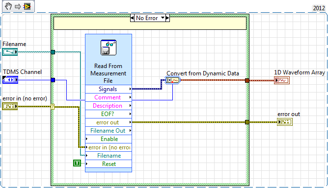
Create graphics using multi-channel for measures and another single channel for the datetime type.
Hello world
I'm using Labview and DIAdem to create graphical reports and I use screws of connectivity and not the Express VI.
The data is stored in a data base MySQL Inno.
I use the following command to get the data I want to show the graphic report!
SQL_ExecDirect (' select 'TimeStamp', 'Value' by 'TableX' where and taste =' %s and channel =' %s; "" ")
And then I use:
SQL_BindChannel ("Datetime1C1", "TimeStamp", "t", "#yyyy - mm - dd hh") to bind the data to the X axis of the graph.
And after that, I use:
SQL_BindChannel("SampleN","Value","n") to bind the data to the axis of the graph Y.
I want to create the chart with more than a sample, I use the commands above on a loop.
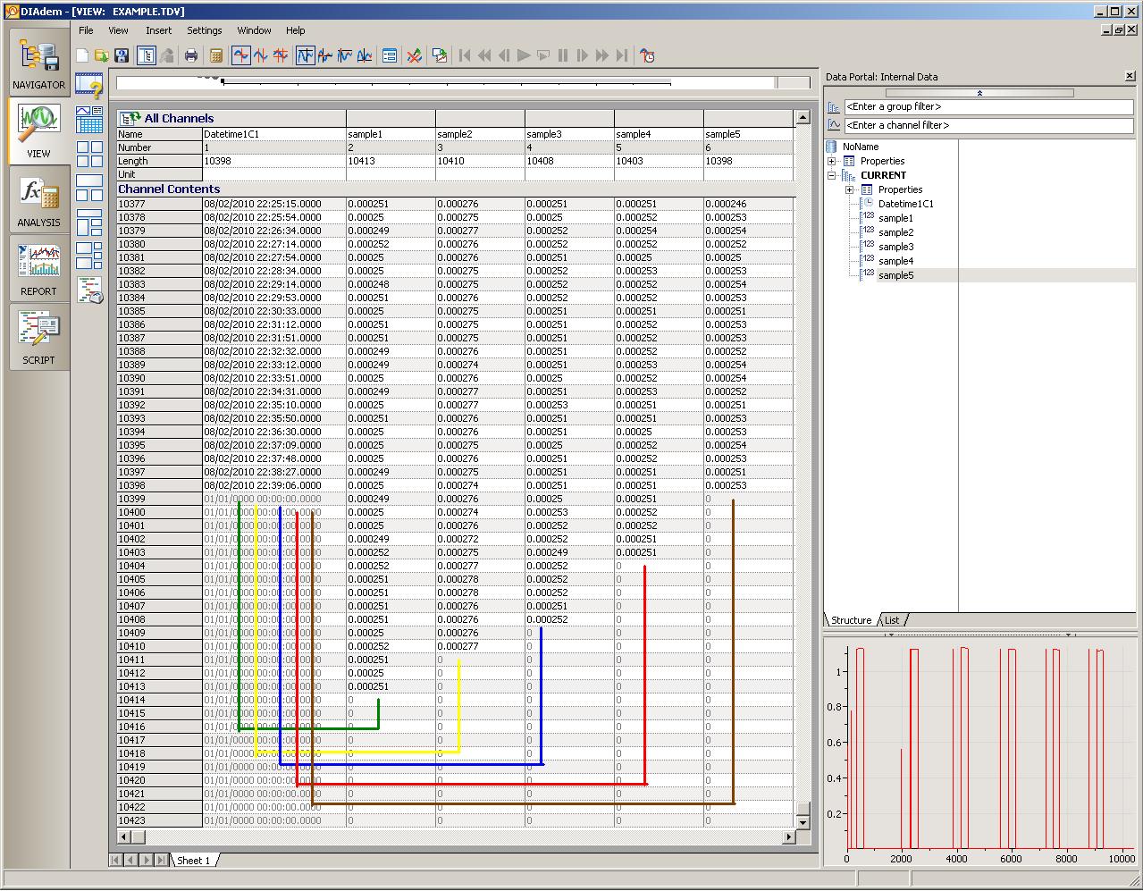
Now here's a printscreen of my problem.
In the first iteration (green line), DateTime1C1 has the timestamp for sample1 but in the second portion (yellow line) DateTime1C1 has the timestamp for sample2, the third iteration (blue line) DateTime1C1 timestamp for sample3. etc.
The time stamp of origin for each sample are 'lost' he re-wrote datetime1C1. and in the end, it shows only the timestamp for the 5th iteraction.
How can I create a single graph with several lines (samples) and datetime an axe?
THX in advance
Hi AlexandreHSCas,
If I understand your situation, the only thing you need to change is to create a new group in the DataPortal before each request.
FOR i = 1 TO iMax
NewGroupName = "application" & I
Call GroupCreate (NewGroupName)
Call GroupDefaultSet (GroupCount)
Call SQL_ExecDirect ("select 'TimeStamp', 'Value' from ' TableX" including Sample =' %s and channel =' %s;) ")
Call SQL_BindChannel (NewGroupName & "/ Datetime1C1", "TimeStamp", "t", "#yyyy - mm - dd hh")
Call SQL_BindChannel (NewGroupName & "/ SampleN", "Value", "n")
NEXTThen you can simply drag each group from the data on the same graph XY-portal, because each group has its own time warp, data points will be displayed correctly placed on the common X axis of the graph.
Brad Turpin
Tiara Product Support Engineer
National Instruments -
How to import a single channel of different TDMS files?
Hello
I have several tdms files which have the same structure of channel (ch1 - chx). Each channel by tdms file has a stored value.
I would like to see the same channel, lets say ch1, of EVERY file of PDM, in order to have a responsible for all the tdms files 2D field
the data portal.
If I drag a channel from a PDM file, loaded on the data portal, I see a value of course. I would like to drag lets say five
channels at once to get a 2D-plot in the display section.
Is there an easy way to solve the problem?
Thank you in advcance
Hi Norick_17,
I think you could do that with advanced search in the browser of DIAdem.
Configure advanced as the attached picture. You can configure the search, so that you find ch1 on all files. Also, the select the minimum/maximum/average as additional search criteria.
In the list of results, you will see a Channel.Maximum column. You can select this column and drag & drop it into your data portal. Each maximum value will be concatenated to a string.
Best regards, Stephan
-
USB-6008 LABVIEW 8.2. SINGLE CHANNEL WITH DBL INPUT VOLTAGE OUTPUT COMPARISON
I AM WRITING A PROGRAM THAT USES A SIMPLE USB-6008 ANALOG INPUT CHANNEL. I WANT TO READ CONTINUOUSLY THE VOLTAGE FOR 60 SECONDS. I WANT TO COMPARE A TENSION FOR THE PREVIOUS OF THIS SAME CHANNEL VOLTAGE, MAINLY FOR THE PERIOD OF TIME MAX VOLTAGE GIVEN, THEN GET A FINAL VOLTAGE READING. THE OUTPUT OF THE VI IS A DBL. I WANT ONLY TWO TENSIONS OF EXPORT TO EXCEL. TO SAVE TIME, I KNOW HOW TO EXPORT. CAN SOMEONE HELP ME WITH THIS ONE.
VI needs an register shift related to the Max & Min function. The current value would be the entrance is and the entrance of x is the left shift register. The max value gets wired for the shift register to the right. Don't forget to initialize it. The output of the shift register is the max you would write and the value of the DAQmx Read out of the loop of wire will give you the last reading.
Your waiting for 45 seconds makes no sense since you said that you wanted to read continuously. You also said that you wanted to read 60 seconds and all this logic is missing. A simple function of time elapsed, it's all you need.
-
6218 USB OR on Mac OS - read only 8 differential channels?
agree General information, I am an architect of LabVIEW, been drawing code almost 16 years on the PC. A customer needs a MAC OS data acquisition system - I use a new MacBook Pro with a NI USB 6218 OR DAQmx Base 3.4 (btw this download of NI DAQmx Base came with C examples only and not LabVIEW, whats with that?) In any case, after a bit of a learning curve, I have the voltage reading material (Dev1 / ai0:7) (unfortunately) is not as robust as it is on a PC, but it works. The 6218 is 32 channels SE or 16 differential, but if I try to play 16 channels (Dev1 / ai0:15) I get the following error:
Error 200077 specific configuration of terminal of input value is not valid for this channel
I'm attaching a VI small I used to get the material upward and running.
Any comments would be very welcome
thanx
lmd2
This is not the appropriate channel list. When you select differential, ai0 is paired with ai8, ai1 is paired with ai9, etc.. You don't list the second string in the pair, so for 16 channels, you must specify Dev1 / ai0:ai7, Dev1 / ai16:ai23
-
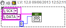
Devantech TPA81 read temperature table "physical channel be unspecified.
Hi, I'm new to Labview.
I need to use a heat of TPA81 sensor in my Dani robot project, so I found the 'Devantech TPA81 reading temperature table' example in examples of robotics. I connect my sensor with a USB - I2C converter and then connected to my PC. I run the program, but the problem "the physical channel is not specified" still exists. How to choose the physical channel in labview for the clock channel and the data channel?
Could someone please help me and thank you in advance.
Jason
Hello.
The example given here "Matrix of the temperature read Devantech TPA81", works with acquisition cards supported by the driver "DAQmx" therefore, I think that this will not work with a simple "USB - I2C" converter.
Now, on the other hand, if you just want to work with the "TPA81" sensor in the robot, DANI, you could see the example "Devantech TPA81 (FPGA). Lvprog' in the help of LabVIEW, where, in the "target FPGA", you will find the VI "Devantech TPA81 (FPGA). saw', where you can configure the channels (data and clock).

Maybe you are looking for
-
Why the GeForce Go 7600 is not supported by any driver Nvidia?
Why this video card is not supported by any driver on the web of the nvidia drivers?
-
Where can I get en_office_web_apps_x64_517488.exe
Where can I get en_office_web_apps_x64_517488.exe for Office Web Apps for SharePoint 2010 Enterprise
-
My computer is slow and I checked the event viewer, and it says I have reached my limits of interruption of security. I ran Netstat-no, but data flashed on the screen, but I can't freeze it at the screen to display the data. What keys down to hold th
-
I can't stop it because I have not all programs that are running.
-
Verification of Windows 7 Home Premium
I am trying to download Windows 7. After verification it will be only let me download in the Korean language. I want the English version, but on the Korean language drop is the only choice.