Peer to peer streaming SMU 1082 and FPGA 7976
Hello Arjun,
I went through the excerpts you provided. After you have created the P2P stream, you will need to enable it also. It would be better if you can go through the examples in the LabVIEW for P2P streaming. Please see the excerpt that I attached the vi and also comes with LabVIEW example. You can directly use the project by changing the FPGA target than yours and use.
Hope this helps
Tags: NI Hardware
Similar Questions
-
Peer to peer between SMU-5451 and SMU-7966R
Hello
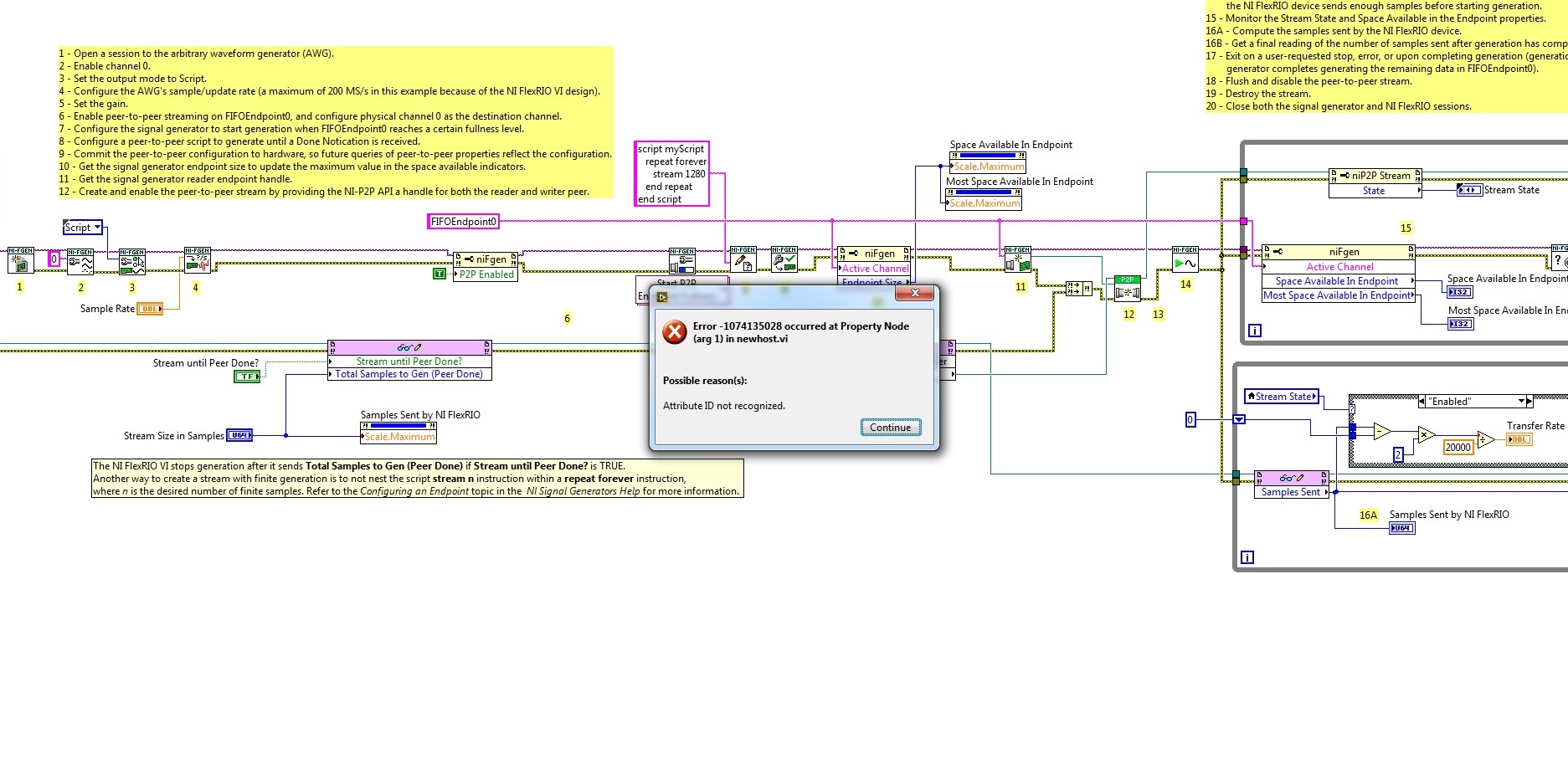
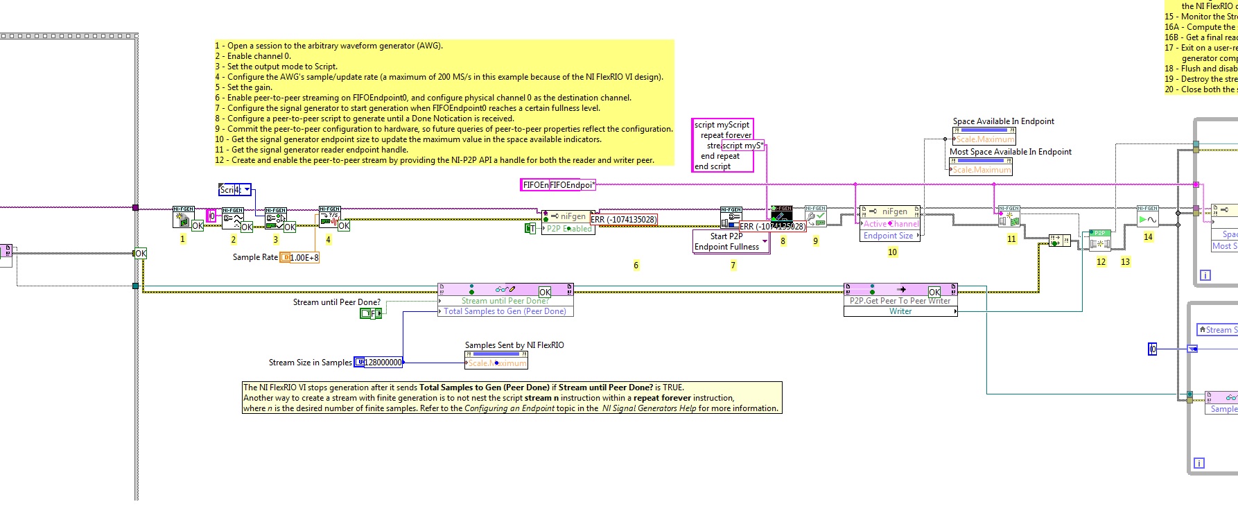
I would like to connect two devices - SMU-5451(waveform generator) and SMU-7966R(NI FlexRIO) with the P2P streaming. I want to transmit data from FPGA to the generator and I took the example of NOR-FGEN. When I started host-vi, there is an error (see photo).
What I am doing wrong?
Try to set the Active Channel property before the active P2P. Property nodes run from top to bottom, so the Active Channel property must be set before calling the property Enabled of the P2P.
-
Automation explore virtual SMU-1082
I have just ordered a PXI system of NOR and want to start programming while I wait for delivery. I thought that I could create virtual devices SMU to do this, but I could be wrong in my understanding of the MAX program. While I have used LabVIEW for almost a decade, I never needed to use "measurement and Automation Explorer."
When I chose "create new" under "devices and interface" "Simules NOR-DAQmx..." ", I couldn't find the SMU-1082 chassis or the module(PXIe-8840) of base I will use. Am I going about this all wrong?
Thank you for your help,
Ron
Hi Ron,
Unfortuantely, you will not be able to simulate a chassis SMU or controller in MAX. The SMU chassis will automatically identify in MAX when you plug on your computer, while some of our former PXI chassis will have to manually identify. If you want to simulate a chassis, you can simulate a PXI chassis and put your modules SMU simulated in it.
The good news is that you don't need to simulate a chassis in order to simulate a card. To simulate the 4304 to the MAX:
- Click devices and Interfaces
- Select create new...
- Select the simulated device NOR-DAQmx or modular Instrument
- You can search for 4304 and select the module.
I will note, the SMU-4304 is first supported in our driver NOR-DAQmx 15.1.1. If you have an older version of DAQmx installed, the device does not appear as an option in MAX.
-
Dear community,
I am trying to implement a background basket (software) PXI trigger on a chassis NI SMU-1082 with LabView 2015 (32-bit) running on an SMU-8135:
HS-DIO (SMU-6544) in slot 2,
-Acquisition of data (SMU-6363) into the Groove 4,
-Flex RIO (SMU-7962R + OR-6583) in the Groove 3.
The trigger schema is explained in the attached file ' LV-PXItrig-HSDIO-DAQ - overview.jpg ".
Scenario 1: written DAQ analog signal and sends signals trigger HS-DIO (software) through bottom of basket, after East of waveform of the complete signals to DAQ for acquisition.
Scenario 2: logical impulse on an external port HS-DIO triggers signals HS-DIO, after HS-DIO waveform is complete DAQ triggered for the acquisition of the ADC by the backplane.
In principle this breaks down to send a trigger of module A to B by PXI backplane. The SMU-1082 chassis has a bus trip with 8 lines (PXI_trigX, X = 0,..., 7) more a trigger in Star controlled the slot 2.
I've linked to implement a software trigger, but I can't access the refreshing resource and execution, see the attachment. Other ways of implementation including the DAQmx Terminal / routine disconnect Terminal have not worked for me either. I am aware about the connection of trigger using the node property VISA but I can't make a trigger.
Tips, comments or solutions are appreciated. Thank you!
For scenario 1, you want to trigger the HSDIO acquisition to begin as soon as the analog output DAQ starts? You can use
DAQmx Export Signalto send the trigger for the start of one of the lines from the Trig PXI backplane. Then, you need to configure your HSDIO acquisition to use a trigger digital beginning on the same line of trigger. Take a look at the example of the "Dynamic hardware generation start trigger" in the Finder of the example (help > find examples)For scenario 2, looks like you do a dynamic unit HSDIO generation when a digital trigger arrives on one of the PFI lines. Once the build is complete, you want to send a trigger for the DAQ hardware to begin sampling. If this is the case, you again use a trigger to start material in your task of NOR-HSDIO, as you did for scenario 1, but use external trig line as the source, rather than the bottom of basket. There is no case of material when the build is finished, but you can use a marker in script mode event instead. The example of the Generation with dynamic event marker' in the example Finder gives a good starting point for this type of operation. You'll want to set the output terminal for the event to be a line of backplane trig, and then tap the DAQmx to start on the same line trig trigger.
-
I work in the lab of Windows (so please don't give me all the answers Lab View).
I have a utility Windows Lab that I support, and I'm doing work on the SMU-1082. We will control the SMU with a MXIe (SMU-8360) connected to a PC.
One thing I want to do check if the SMU-1082 is connect (or my computer is running it on an ordinary PC).
I have serached the forums and can't find anything.
I can not even find any funcitons that can query the SMU box to check something like maps in particular slots (I thought if I ould read if a card is present in a slot, I might be able to use something like this to determine if I was running with the SMU box!)
Hello Ken,
If you have downloaded the API NEITHER of System Configuration:
http://www.NI.com/download/NI-system-configuration-5.5/4086/en/
You can run the example CVI "ShowAllHardware.prj." From the finder of the example, it is on "Hardware input and output-->--> ShowAllHardware.prj System Configuration." If you run this project and choose "localhost" when it asks you to enter the host name, you will get a list of all the devices connected to your machine. One listed is the MXI Express card that you use to connect to the chassis.
I hope this helps a bit!
Happy holidays!
-
I have an SMU-5672 and capture the baseband on an oscilloscope. Can I do this?
I have a generator of signals Vectoriels SMU-5672 and to capture the baseband with a reach to compare synchronization with my receiver (HAD). I would like to connect a scope to the SMU-5442, but don't know if that problem. Of course, I am particularly concerned by damaging the material. This method would be the ideal way to check my timing of answer, but if you can't, I'm open to other suggestions.
Yes, you can do it. The device driver 5672 configures the 5442 for use is the direct path. Direct tension max is 1 Vpp into 50 Ohm, 2 Vpp scope in high impedance, so make sure that your scope is put in place for this.
Continue to use the 5672 as usual, but with your scope related to the CH 5442 0 output. Assuming that the scope leads his entry (should not), there is no concern damaging the 5610 or 5442 by doing this.
Unless split you the signal (not what I say), you won't get a signal off the 5610. It is not clear how you planned to compare the signal for synchronization with your DUT. No signal can be OK if you compare the time vs a trigger digital, may be exported from the 5442. Be aware, however, that IF IN addition to RF Out 5610 is about 1.2 US.
Also note that if you set NIRFSG_ATTR_COMPENSATE_FOR_FILTER_GROUP_DELAY to true, and a marker on sample output 0 event, event marker will be delayed to address delays in the processing of signal in the 5442 and delay analogue 5610, causing the marker event should be harmonized with the time "sample 0" appears on the RF Out 5610. This attribute was added after the original version and the default values to false to preserve backward compatibility.
If you are looking to compare calendar, setting the true Compensate for filter Group delay is actually what I would do rather than split the signal IF Out 5442. You can check how much are aligned by tuning the 5672 at a fairly low frequency for your bezel measure. 5610 late is dominated by the IF filter, which is independent of the RF frequency.
-
USRP RuntimeError: Please update the firmware and FPGA images for your device.
Hello
I have an Ettus USRP N210 with a surfboard RF WBX running FPGA firmware version 4.
2009 LabVIEW and NOR-USRP 1.1
When I try to run one of the USRP VI OR as devices to find it displays the following error code:-1074118627
"niUSRP Devices.vi find
a length or configuration error has occurred."
Code: 1440
Details: RuntimeError:
Please update the firmware and FPGA images for your device.
See application for USRP2/N-Series notes for instructions.
Compatibility of the Protocol expected number [7-11], but received 12:
The version of the firmware is not compatible with the host code generation. »I can communicate with unity on Linux using UHD machine and the utility Configuration NI USRP can see the device, but firmware update is not possible, probably because of my IP ending in 221. Latest firmware Ettus was recharged via Linux UHD.
Looks like my firmware again? I am not allowed to download the old versions of the FPGA firmware.
Can someone help me with this problem please?
With respect,
-Sigurd has.
Hello Sigurd,
The NOR-USRP driver requires a specific firmware and FPGA image to be downloaded to the USRP to exploit.
You can use the utility of Configuration USRP download appropriate firmware and FPGA image to the usrp.
This knowledge base article will help you: how update the Firmware and FPGAS Images for N2xx and NI 292 x USRP
-
Could Scan mode and FPGA mode be used in a project?
Hi all
I need a project that the current NI9203 with mode of analysis samples and samples of the accelerometer of the NI 9237 with FPGA mode. It could be achieved? Could Scan mode and FPGA mode be used in a project?
I use labview2009.
Thank you very much.
Yes, they can. This mode is called hybrid mode. To use the Mode of LabVIEW FPGA IO modules, simply slide the module to the target FPGA in the LabVIEW project, disconnected from scan mode. Then use LabVIEW FPGA to program the modules and use I/O variables for read and write I/O on the remaining modules. When you use a LabVIEW FPGA Mode on one or more modules, the logic of the scan Mode CompactRIO on the FPGA, known as the RIO Scan Interface, is compiled in a single application of FPGA with LabVIEW FPGA VI. If no module is configured to use the scan mode, the RIO Scan Interface is not included in the compilation.
-
Hey Gang,
I spent the day to set up a new system of cRIO and a new installation of LV2012 RT and FPGA Softmotion.
Our system uses a CAN interface, which, we learn, requires the use of FPGA mode. Maybe this isn't a bad thing, because we are concerned about the speed of the scan mode. I developed an FPGA application before.
My main concern is right now, to get the job of control of movement stuff. Our movement is a NI - 9514. I hope there is a way to use the SoftMotion modules with the FPGA interface. Otherwise, the movement FPGA examples look REALLY discouraging!
All I do is homing and simple relative motions. I enjoy all help/advice on the simple/fast way to get there.
Thank you!
Roger
Hi Roger,
You can use the 9514 without using the "formidable" examples using the cRIO in hybrid mode. There are good instructions on how to do it here. A quick summary, is to put the modules you want to use in scan mode under the chassis and modules you want to use FPGAS in the FPGA. When you compile the FPGA bitfile, RIO scan interface is compiled for modules that are under the chassis so that you can use in scan mode. A few warnings:
- The FPGA VI must be running to use the 9514. When you are in scan mode, the FPGA runs automatically without requiring you to do so. However, in hybrid mode, the FPGA does when you run it explicitly.
- The FPGA VI should work for deploy you the settings of the axis of the target. This can be a bit awkward during development when you make changes to the configuration of the axis. Usually, you run the FPGA VI using the open FPGA VI reference in a RT VI. However, when you run a RT VI, it checks to see if the deployed data are compatible with the project data and if not, invite you to deploy. Don't forget, however, that you cannot deploy your FPGA VI because is not yet running (since it won't work until the open FPGA VI reference runs). When you try to deploy, you will get an error (I think it's something like "E/s Module not found"). What I do usually is during development, run the FPGA VI manually (by pressing the run button). You can then run your VI RT which uses the FPGA VI reference and everything will work. You will encounter this problem only if you change the configuration of the axis of the project (and so won't be a problem for your final application when changing your aern can't axis settings). If you change the configuration of the axis programmatically, you do not experience this problem.
As a note side for those who use the 951 x modules of movement, unless you really need to do something custom, you must use the modules of 951 x in scan mode. The performance is better in scan mode it is using FPGA (assuming you want to use the API SoftMotion high level (EXVIs, blocks of functions or properties/methods)). When you use FPGA mode, there is further delay to obtain the data of the FPGA in the SoftMotion engine. In addition, you are always coupled to the scan engine! If you get the worst performance, a more difficult experience, and you don't even remove the need for the analytical engine. There are valid reasons to use the modules of 951 x on the FPGA (for example custom control loops), but most applications I've seen use FPGA would be better served by using the module in scan mode.
Thank you
-
Capture Capture stream contains transactions and spills
I wanted to clarify something on the subject of capture streams. I saw a weird behavior that broadcasts continuously if I do a big update on a huge table, then roll back the transaction, starts to spread the settlement transaction. My question is why is stream capture messages and the reversals of them when they are not committed? Is there any config setting I'm missing?
Thank you
KevinAn uncommitted transaction in a streams environment is also well captured and propagated but not enforced. The settlement does not apply to a transaction to stop. In case of a cancellation of a transaction, the capture process creates ADR for do it again generated and place these ADR according to the rules specified for the capture process. The ADR are propagated to the destination site according to the propagation rules. Apply it treat assmebles the ADR in a transaction and then applies them in the correct order when the COMMIT message is received. For transactions ending in a restoration, imputation does not apply the changes in the ADR for this transaction.
-
Hello
Thank you for your questions. Here are answers to your scenarios:
Scenario 1: The data pass directly through P2P and will forward not by the controller, delivers data across the switch. The bandwidth required is determined by the rate of your acquisition, but the switch must not be the limiting factor when it comes to bandwidth.
Scenario 2: The path of data will be the same as scenario 1 except for the addition of data routed from the 5622, through the switch, then through the plan back to the controller, then the 8265 through the background. The 1075 has a 1 GB/s per slot coupled with a controller bandwidth NI SMU-8133 (2 Gbps per slot bandwidth) would allow constant streaming.
If you want to send your 8265 data via ethernet using the first scenario data will be will make of the 8265, along the bottom of the basket, to the controller, then walk through the ethernet port on the controller.
The second scenario provides no additional benefit because the limiting factor will not be output from the controller's ethernet port speed, but the speed of data transfer its auto TCP/IP. The stream, however, would be of the 8265, through the plan back to the controller, the controller, through the back and out the 8234.
I hope that answers your questions.
Kind regards
Marcus
-
peer cvpn through pix and ending the pix
cvpn-= pix = - internet-= point of termination vpn (pix) =
Can someone point me to a document or explanation on why ipsec must be open on the first pix to IPSEC to cross because he hails from this network? I can't find a document that explains better that I can or includes the above scenario for the layman.
The PIX opens only the holes for the return for TCP and UDP based traffic. IPSec ESP is located just above IP and is therefore not based TCP/UDP. For this reason, you must specifically allow Protocol IP 50 (ESP) in the PIX from the outside, because as I said, the PIX will not open a hole to get him back.
He done the same for the ICMP protocol, it takes of icmp in the PIX, if you want your interior to the users to be able to ping outside guests. Because ICMP is not based of TCP/UDP, the PIX does not open a hole for the return to return to traffic.
Now, that said everything that, in point 6.3, they added a '' correction '' ESP, so the PIX could inspect the outbound ESP for A a SINGLE TUNNEL, he PAT to the address of the external interface and allow the return of traffic to. It is disabled by default, you can activate it with the following text:
fixup protocol esp-ike
You can read about it here:
http://www.Cisco.com/univercd/CC/TD/doc/product/iaabu/PIX/pix_sw/v_63/cmdref/DF.htm#wp1067379
-
SMU-7975R with FPGA Kintex-7 - LVDS problem
Hello
I developed a custom RIO FLEX module (Digitizer18, 0xAB66 - vendor id) and try to use it with the card 7975R-SMU-FPGAS (FPGA Kintex-7)
I have a problem, try output LVDS signal via aUserGpio (61) and aUserGpio_n (61).
These pins are not K7 capable clock, but I used this module FLEX RIO with SMU-7962R (Virtex-5 FPGA) where these pins are capable REGIONAL clock and it worked fine.
Kintex-7 it compiles without error, but I see no signals on the pins aUserGpio (61) and aUserGpio_n (61), although its switching State is ADC2_FSM.
Is it possible to use pins that is not capable of WHAT LVDS output or I am condemned to use MRCC clock or pins SRCC?
Thank you
My xdc file (aUserGpio (61) and aUserGpio_n (61) belong to the 18 Bank):
set_property IOSTANDARD LVDS_25 [get_ports {aUserGpio [61]}]
set_property FAKE DIFF_TERM [get_ports {aUserGpio [61]}]
set_property IOSTANDARD LVDS_25 [get_ports {aUserGpio_n [61]}]
set_property FAKE DIFF_TERM [get_ports {aUserGpio_n [61]}]# all unused pins Bank 18 are LVCMOS25
set_property IOSTANDARD LVCMOS25 [get_ports {aUserGpio [49]}]
set_property BUNCH SLOW [get_ports {aUserGpio [49]}]
set_property DRIVE 8 [get_ports {aUserGpio [49]}]
set_property BIO FAKE [get_ports {aUserGpio [49]}]...
part of my clip to vhd file (because it's too big and all other LVTTL logic works very well except LVDS):
attribute dont_touch: string;
Signal ADC2_CNV_buf: std_logic_vector: = '1';
attribute dont_touch of the ADC2_CNV_buf: signal is 'true '.OBUFDS_ADC2_CNV: OBUFDS
map of port)
O-Online aUserGpio (61)-Diff_p output (connect directly to the port of higher level)
OB-online aUserGpio_n (61)-Diff_n output (connect directly to the port of higher level)
I have-online ADC2_CNV_buf - the input stream
);....
process (LVDS_CLK) - 200 MHz
Start
If LVDS_CLK' event and LVDS_CLK = "1" then
ADC2_FSM case is
When s0 =>
If ADC2_CNV = "0" then
ADC2_timer1 <= (others="">' 0');
ADC2_timer2 <= (others="">' 0');
ADC2_CLK<=>
ADC2_READY<=>
ADC2_CNV_buf<= '1'="">
ADC2_FSM<=>
end if;
When s1 =>
If ADC2_CNV = "1" then
ADC2_CNV_buf<= '0'="" ; ="" ="" ="" ="" ="" ="" ="">
ADC2_RESET<= '1'; ="" ="" ="" ="" ="" ="" ="" ="" ="">
ADC2_FSM<=>
end if;
When s2 => ADC2_FSM<=>
When s3 => ADC2_FSM<=>
When s4 => ADC2_FSM<=>
When-online s5
ADC2_CNV_buf<= '1'="" ; ="">
ADC2_RESET<=>
ADC2_FSM<= s6;="" ="">
When-online s6
If ADC2_timer1< x"28"="" then="" --="">
ADC2_timer1<= adc2_timer1="" +="" 1;="">
on the other
ADC2_FSM<=>
end if;
When s7 =>
ADC2_CLK<= not="">
If ADC2_timer2< x"24"="">
ADC2_timer2<= adc2_timer2="" +="">
on the other
ADC2_READY<=>
ADC2_FSM<= s0; ="" ="">
end if;
When other => ADC2_FSM<= s0; ="">
end case;
end if;
complete the process;-the host uses the flank amount of DCO± to capture D±
process (UserGClk2, ADC1_RESET) - echo DCO2 clock
Start
If ADC1_RESET = "1" then
ADC2_READ_FSM<= s0; ="">
ADC2_BUF <= (others="">' 0');
elsif UserGClk2' event and UserGClk2 = '0' then - host uses the flank amount of DCO± to capture D±
ADC2_READ_FSM case is
When s0 => ADC2_BUF (17)<= not="" d2="" ;="" adc2_read_fsm=""><=>
When s1 => ADC2_BUF (16)<= not="" d2="" ;="" adc2_read_fsm=""><=>
When s2 => ADC2_BUF (15)<= not="" d2="" ;="" adc2_read_fsm=""><=>
When s3 => ADC2_BUF (14)<= not="" d2="" ;="" adc2_read_fsm=""><=>
When s4 => ADC2_BUF (13)<= not="" d2="" ;="" adc2_read_fsm=""><=>
When s5 => ADC2_BUF (12)<= not="" d2="" ;="" adc2_read_fsm=""><=>
When s6 => ADC2_BUF (11)<= not="" d2="" ;="" adc2_read_fsm=""><=>
When s7 => ADC2_BUF (10)<= not="" d2="" ;="" adc2_read_fsm=""><=>
When s8 => ADC2_BUF (9)<= not="" d2="" ;="" adc2_read_fsm=""><=>
When the s9 => ADC2_BUF (8)<= not="" d2="" ;="" adc2_read_fsm=""><=>
When s10 => ADC2_BUF (7)<= not="" d2="" ;="" adc2_read_fsm=""><=>
When s11 => ADC2_BUF (6)<= not="" d2="" ;="" adc2_read_fsm=""><=>
When s12 => ADC2_BUF (5)<= not="" d2="" ;="" adc2_read_fsm=""><=>
When s13 => ADC2_BUF (4)<= not="" d2="" ;="" adc2_read_fsm=""><=>
When s14 => ADC2_BUF (3)<= not="" d2="" ;="" adc2_read_fsm=""><=>
When s15 => ADC2_BUF (2)<= not="" d2="" ;="" adc2_read_fsm=""><=>
When s16 => ADC2_BUF (1)<= not="" d2="" ;="" adc2_read_fsm=""><=>
When s17 => ADC2_BUF (0)<= not="" d2="" ;="" adc2_read_fsm=""><=>
When s18 => ADC2_READ_FSM<=>
When other => ADC2_READ_FSM<= s0; ="">
end case;
end if;
complete the process;
ADC2_DATA<= "00000000000000"="" &="" adc2_buf="">I've made a few changes to TestCLIP.fam:
...
[FlexRIO-K7IOModule]
DefaultCLIP = TestCLIP
VccoLevel = 2.5...
And my xdc file now looks like this:
# Set the voltage from Bank to Bank 18.
#set_property IOSTANDARD LVCMOS25 [get_ports-filter {IOBANK == 18}]set_property IOSTANDARD LVCMOS25 [get_ports {aUserGpio [*]}]
set_property IOSTANDARD LVCMOS25 [get_ports {aUserGpio_n [*]}]
set_property IOSTANDARD LVDS_25 [get_ports {aUserGpio [58]}]
set_property IOSTANDARD LVDS_25 [get_ports {aUserGpio_n [58]}]
set_property IOSTANDARD LVDS_25 [get_ports {aUserGpio [67]}]
set_property IOSTANDARD LVDS_25 [get_ports {aUserGpio_n [67]}]Now it's working.
-
A stream of publication and reading has a persistent connection to Stratus?
I've been using Stratus for awhile now, and I find the idea quite intriguing.
I can see that the information is sparc, and my conclusions tell me that Stratus is a kind of service «peers locator» Of course, you can't really talk about peer-2-peer, when a central service is used anyway. Well, maybe just at the level of the network. I'm guessing the peer identifiers which are exchanged for set up of direct flows on a connection to Stratus, encode the addresses and ports where Flash Player instances exchange the data of actual data stream.
If this is the case, why can we (and Adobe themselves) need maintain the connection between a client and the service, once a peer based f.e.?
I mean after a peer ID a valid counterpart, if they should not be able to take it from there, without over loading and taxing the server? Of course, which would free Adobe to load on the server as well?
Note that the load, that we have seen recently would have been much worse with intermittent connections, the load was caused by research peerID, users not concurrent or churn of connection.
-
My missing photos on the Win10 stream. Download and share the work very well.
I lost hours trying this at work, but I am confused. I want to take a picture on my iPhone and do appear in iCloud my photo stream on Windows 10. It works on all my Apple devices. Share your albums on Windows work. Download Windows also works to put the things in my photo stream on all my other devices. The Downloads folder is under the Photos of iCloud on Windows, but there is no record of My Photo Stream and no picture appears after several reboots, connections, reinstalls, restarts, and everything else I can think of. I even deleted the content of MediaStream. No luck. This should be simple, but I can't make it work.
Did you already try uninstalling and reinstalling iCloud?
Maybe you are looking for
-
Satellite C650 does not read 4 GB mirco SD card
Hello I have a problem reading my micro SD card. It is not a HS card, just a normal mirco SD 4 GB card.I insert it into the SD slot, but my computer does not respond what so ever. I downloaded the Realtek card reader but stil nothing.I'm afraid that
-
Our district has recently purchased a HP Pavilion TouchSmart Sleekbook 15. We need these machines to run windows 7 and I'm looking for a list of the drivers I need for machines. We will run the 64 bit OS 15 - b129wm of the model Will be grateful if s
-
Topics series & parallel in MAX
Hello I have a problem with an installer. Parameter I pour it installs NI DAQmx and NI MAX. The installation goes well but I did not all topics when text MAX in particular the reference series & parallel located in the peripheral topic and interface.
-
Pavilion 17-e118d: Y at - it a map available for the 17-e118dx Bluetooth
I am considering the purchase of this laptop, but wanted to know if there is a bluetooth card avialable for this device.
-
Outline of the block diagram flashing red
Hello. I don't have access to the Vi in question at the moment so I'll make it as General as possible. My Vi worked properly for a week or two, but today it started to flash red around the edge of the block diagram. Once the Vi makes the block diagra