SoftMotion and FPGA OR 9514
Hey Gang,
I spent the day to set up a new system of cRIO and a new installation of LV2012 RT and FPGA Softmotion.
Our system uses a CAN interface, which, we learn, requires the use of FPGA mode. Maybe this isn't a bad thing, because we are concerned about the speed of the scan mode. I developed an FPGA application before.
My main concern is right now, to get the job of control of movement stuff. Our movement is a NI - 9514. I hope there is a way to use the SoftMotion modules with the FPGA interface. Otherwise, the movement FPGA examples look REALLY discouraging!
All I do is homing and simple relative motions. I enjoy all help/advice on the simple/fast way to get there.
Thank you!
Roger
Hi Roger,
You can use the 9514 without using the "formidable" examples using the cRIO in hybrid mode. There are good instructions on how to do it here. A quick summary, is to put the modules you want to use in scan mode under the chassis and modules you want to use FPGAS in the FPGA. When you compile the FPGA bitfile, RIO scan interface is compiled for modules that are under the chassis so that you can use in scan mode. A few warnings:
- The FPGA VI must be running to use the 9514. When you are in scan mode, the FPGA runs automatically without requiring you to do so. However, in hybrid mode, the FPGA does when you run it explicitly.
- The FPGA VI should work for deploy you the settings of the axis of the target. This can be a bit awkward during development when you make changes to the configuration of the axis. Usually, you run the FPGA VI using the open FPGA VI reference in a RT VI. However, when you run a RT VI, it checks to see if the deployed data are compatible with the project data and if not, invite you to deploy. Don't forget, however, that you cannot deploy your FPGA VI because is not yet running (since it won't work until the open FPGA VI reference runs). When you try to deploy, you will get an error (I think it's something like "E/s Module not found"). What I do usually is during development, run the FPGA VI manually (by pressing the run button). You can then run your VI RT which uses the FPGA VI reference and everything will work. You will encounter this problem only if you change the configuration of the axis of the project (and so won't be a problem for your final application when changing your aern can't axis settings). If you change the configuration of the axis programmatically, you do not experience this problem.
As a note side for those who use the 951 x modules of movement, unless you really need to do something custom, you must use the modules of 951 x in scan mode. The performance is better in scan mode it is using FPGA (assuming you want to use the API SoftMotion high level (EXVIs, blocks of functions or properties/methods)). When you use FPGA mode, there is further delay to obtain the data of the FPGA in the SoftMotion engine. In addition, you are always coupled to the scan engine! If you get the worst performance, a more difficult experience, and you don't even remove the need for the analytical engine. There are valid reasons to use the modules of 951 x on the FPGA (for example custom control loops), but most applications I've seen use FPGA would be better served by using the module in scan mode.
Thank you
Tags: NI Software
Similar Questions
-
USRP RuntimeError: Please update the firmware and FPGA images for your device.
Hello
I have an Ettus USRP N210 with a surfboard RF WBX running FPGA firmware version 4.
2009 LabVIEW and NOR-USRP 1.1
When I try to run one of the USRP VI OR as devices to find it displays the following error code:-1074118627
"niUSRP Devices.vi find
a length or configuration error has occurred."
Code: 1440
Details: RuntimeError:
Please update the firmware and FPGA images for your device.
See application for USRP2/N-Series notes for instructions.
Compatibility of the Protocol expected number [7-11], but received 12:
The version of the firmware is not compatible with the host code generation. »I can communicate with unity on Linux using UHD machine and the utility Configuration NI USRP can see the device, but firmware update is not possible, probably because of my IP ending in 221. Latest firmware Ettus was recharged via Linux UHD.
Looks like my firmware again? I am not allowed to download the old versions of the FPGA firmware.
Can someone help me with this problem please?
With respect,
-Sigurd has.
Hello Sigurd,
The NOR-USRP driver requires a specific firmware and FPGA image to be downloaded to the USRP to exploit.
You can use the utility of Configuration USRP download appropriate firmware and FPGA image to the usrp.
This knowledge base article will help you: how update the Firmware and FPGAS Images for N2xx and NI 292 x USRP
-
Could Scan mode and FPGA mode be used in a project?
Hi all
I need a project that the current NI9203 with mode of analysis samples and samples of the accelerometer of the NI 9237 with FPGA mode. It could be achieved? Could Scan mode and FPGA mode be used in a project?
I use labview2009.
Thank you very much.
Yes, they can. This mode is called hybrid mode. To use the Mode of LabVIEW FPGA IO modules, simply slide the module to the target FPGA in the LabVIEW project, disconnected from scan mode. Then use LabVIEW FPGA to program the modules and use I/O variables for read and write I/O on the remaining modules. When you use a LabVIEW FPGA Mode on one or more modules, the logic of the scan Mode CompactRIO on the FPGA, known as the RIO Scan Interface, is compiled in a single application of FPGA with LabVIEW FPGA VI. If no module is configured to use the scan mode, the RIO Scan Interface is not included in the compilation.
-
Peer to peer streaming SMU 1082 and FPGA 7976
Hello Arjun,
I went through the excerpts you provided. After you have created the P2P stream, you will need to enable it also. It would be better if you can go through the examples in the LabVIEW for P2P streaming. Please see the excerpt that I attached the vi and also comes with LabVIEW example. You can directly use the project by changing the FPGA target than yours and use.
Hope this helps
-
sbRIO-9631 digital inputs/outputs using e/s node FPGAS and FPGA of i/o method node
Hello, I'm trying to configure my SBRio-9631 for the first time. I try to use the on boards to inputs and digital outputs. The following code will work? This is a simple "read the entries, 'or' some inputs and pass ' exits." I have to add "E/s method nodes FPGA" between my 'FPGA of i/o nodes"to get"modes of State of sorting for the input and output lines? Also, I can't simulate/test it works, by adding 5 VDC at the entrances, and not have any source of voltage output. Thank you for your time.
Hey, Spex,.
I really, really appreciate your help. Your follow up information was exceptional.
Thanks again for your help and your time.
gjmm
-
cRIO-9082 DMA bandwidth between RT and FPGA
Hello
I would like to know the bandwidth the cRIO-9082 between FPGA and RT DMA? How many MB/s? I can't find the answer on the web page of NOR.
I know that there are 3 DMA channels, but how fast I could send data from FPGA to memory RT?
What is the optimum size of the element in the DMA channel? U8, U16, U32, or U64?
Material: cRIO-9082 RT
Software: LabVIEW 2012, 2012 LabVIEW FPGA
Best regards
Peter
CLA
-
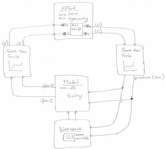
Impose a factor of scale between the model and FPGA
Hi all
I have a VS project configuration that unfolds on a real-time system. The project has an FPGA and a model. Some of the output of the cards of the OD of the FPGA model. In addition, some of the AI of the FPGA cards at the entrances to the model. Here's my problem. The AI FPGA gives me a measure of voltage, but the model takes only a pressure (bar) as input. This means that I need to convert my blood pressure using a table or a formula. How to make that happen?
Also, I want to use the same lvbitx FPGA and the same model of dll on various physical parameters. The only difference between these physical configurations is the forumla/table (for example, a different pressure sensor is used). Is a convinient way to say VS use different table games?
Hi oeua.uoeuau,
If you have a formula to convert the voltage in pressure, you can use a calculated string to implement. You just point to the computed in your Channel FPGA output and the inport of your model to the computed string. If you need a table of choice, you can create a model of LabVIEW that takes blood and uses a lookup table to get the pressure reading and the outport of LabVIEW model port in the inport else your model.
To switch between the different scallings, you can simply use a procedure to set a variable to be an entry or another.
See you soon,.
< brian="" a="" |="" national="" instruments="" |="" applications="" engineering="">
-
PXI data transfer between OTN and FPGA
Hello
I have a DAQ card in my PXI and a FPGA 7813R map.
The problem is that I send sample waaveforms of the data acquisition card to the FPGA card (which only has digital i/o) to launch my control on the FPGA. When I generate a sine wave of 50 Hz in the OTR to simulate a measured signal and send it to the FPGA through the controls in the Panel before (http://zone.ni.com/reference/en-XX/help/371599G-01/lvfpgaconcepts/pfi_data_transfer/) the signal happens on the fpga is much slower than 50 Hz indicating this folding is (it takes too much time to send the data). I tried to use this method of data transfer because my control requires only the more recent data, but it also has a phase lock loop that requires the data arriving at least resemble the original signal. Another criterion is that the control to data more up-to-date as possible. I know there is another option of the use of DMA FIFO, but I use it because I thought it would take more time to send the data, because each value must be sent.
My questions are:
I go about it the correct way? I know that there is the FPGA cards with analog inputs. I buy one it is because I have a large amount of differential analog inputs (20 +)
Is there a quick way to transfer data to the FPGA. (I have converted all the FXP data before writing to the FPGA)
Hi Jagwa,
You should not have to synchronize the RTOS loop that written information and the FPGA VI which is read. Instead, you can simply use a FIFO. In RT, you can write all the data points for the FIFO, and then you can extract them one at a time on the FPGA VI and use them as needed to control functions. In this way, the only time you need to worry about stopwatch the FPGA VI to get out the data to mimic 50 Hz.
Kind regards
-
problem with timing cRio and FPGA
Hello
I develop software for measure the position of a device using some quadrature encoders.
What I do uses the FPGA interface to acquire the position, then send usign real number of the meter to a host pc to create a data file. In the RT environment, I create a table with the position and the time that is acquired and using shared variables I send the array to the host PC.
But I have a problem with the sync. The sampling time is unstable, I use a timed loop to control sampling but after some acquisitions, data sampling period begins to increase, as you can see in the image of attachment file. In the attached picture, I used a period of 250us and after some time gets twice and 3 times longer before you clean the table and begin to create a new table, during the period in 250us again. so the problem is that I should get a stable period in 250us instead of these steps in growing period
You use the table of construction to add new data points? I suggest to use the function "Initialize the array" and "replace the array element. It will reduce the time it takes from the table of the construction.
I can't open your code as I have LabVIEW 2010.
-
Run code on the host target RT and FPGA
Hi all
I'm sorry if I ask a question to repeat. I searched for this a bit and couldn't find a solution.
I'm trying to run a single VI (be it on RT compactRIO or on the connected host PC) and enforce the code on the host PC and target the FPGA code RT. I currently code that runs on the host PC computer that opens the FPGA reference and executes code FPGA, but I don't know how to do this with a VI on the target of RT. Any advice/help would be great. Thank you!
Brandon
You are not far from your goal. But you need to at least
- Update FPGA code (Bitfile) containing your code to run on the FPGA.
- An executable compiled for your goal of RT, which is set to autostart.
You can use the code from my first post as a starting point. Compile, deploy and set it to autostart on your target of RT. - An executable compiled for the host machine. that your user will begin.
You can use the code in my first post, maybe load IP address, Port etc. of the Ini file settings.
If you double-click on the exe file on your host computer it will open an application reference to your target computer of RT and call the VI on the target machine. This is how you run code on your RT. From this RT code you can download and run the FPGA (bitfile) to your FPGA code or control which is already running the FPGA by controlling a state machine code. Load more screws to your memory of RT targets and call them from your host to add more functionality if you need to.
-
I want to use some of my modules in scan mode and others in the FPGA mode. Although I could create a hybrid project, I can't do a VI implementation of two of them. I get an error as in the diagram I have attached. I want to read the analog inputs using NI 9239 scan interface mode and put out through 9269 mode of fpga. Is this possible? I'm kinda new to this.
Thanks in advance!
Of course, you can do what you were trying to here. You must at least two screws for this application. You will need a VI running under the FPGA target who can read and write the purple (FPGA IO nodes) nodes. You will need a VI running under the controller RT who can read and write variables, like the yellow node in your image. To talk between two screws, use the palette FPGA Interface to read and write controls and indicators on your FPGA VI of your RT VI.
This information gets you take off a little at the moment?
-
Pilot LabVIEW 8.6 and FPGA Xilinx SPARTAN 3 departure Board
Is the new LabVIEW compatible driver FPGA Xilinx SPARTAN version 8.6 3rd starting Board?
I mean the download found here...
http://digital.NI.com/express.nsf/bycode/Spartan3E?OpenDocument&lang=en&node=seminar_US
Tutu
Spartan-3F for LV FPGA 8.6 support is under development. Contact your engineer commercial ground NOR or Sapper University if you will need a copy of the draft.
Reid
-
Variables, FPGA, defined by the user and SoftMotion 2012 + NOR 9505
Hello
To http://forums.ni.com/t5/Motion-Control-and-Motor-Drives/Softmotion-and-NI-950X-Module-Compatibility/... Nathan says:
NathanK wrote:
The glue code that connects Softmotion on FPGA LV code RT is called 'the axis interface. The version of the interface of the 2011 Softmotion axis necessary creation screw RT that exposes certain capabilities to Softmotion.
....
Improvements have been made in 2012 Softmotion who has removed the requirement to write RT live. Disclosure for the FPGA happens rather on the Variables (UDVs) user-defined. It is also possible to create a kind of axis 9501 for configuration of the module as well as an axis UDV generic for other completely custom 950 x modules or axes. It is not a specific example for the 9505 yet.
This caught my attention, as I'm trying to develop a system using LabVIEW SoftMotion 2012 and the NI 9505. I'm curious to see if there are alternative methods to write my application.
Where can I find more information on this 'generic UDV axis' and how to implement a? Nathan says "is not a specific example for the 9505 yet", but there are examples for the other modules - how similar/different are these modules from the 9505, and it involves a lot of effort to bring examples of the 9505?
Thank you!
Hi JKSH,
I have some relevant information that it is request that may be useful:
Working with Axes Variable defined by the user (NI SoftMotion Module)
Resource binding dialog box (NI SoftMotion)
Configuration OR SoftMotion Axes (OR SoftMotion Module)
Example that mentions of Nathan is the drive Stepper (9501) .lvproj (material Input and Output"Motion Control" NI SoftMotion"Device Specific" NI 950 x"OR 9501), I would take a peek at this on use of the UDVs.
-
Looking myRIO Xilinx architecting-7010 SoC I am bit inntrested in the workflow for the GS. How does the bennifit myRIO use a system on chip instead of a regulare CPU and FPGA not in the same chip.
4 way could there be to manage a VI?
With FPGA and RT (CPU)
Only of FPGA
Only RT
only the windows
I am comfused, is it any good article/doc describing this?
I found the image in a PowerPoint on the www. -What the task split like this betwheen the CPU and FPGA?
Hello
Please see this link. This can help you understand the architecture of RIO, and there are many whitepapers available in ni.com
-
Typical time a request for interruption takes between RT LV and LV FPGA.
Currently, I don't have the equipment to test it, and I was looking for some statistics calendar all the time it takes for a request for interruption to process between LV RT and FPGA LV (LV RT generate the interrupt request, waiting LV RT on ack, LV FPGA get query pause and LV FPGA ack, LV RT continue). I know that the interrupt request has a priority higher loop timed on LV RT, and a concern for this issue, let me say that the FPGA LV does not what whatsoever between the receipt of the interrupt request and receipt.
Does anyone have any time?
Hello Michel_Gauvin,
I found the following article in the knowledge base that may answer your questions:
Landmarks of Module time real LabVIEW for Applications in the LabVIEW FPGA Module
I hope this helps!
Kind regards
Maybe you are looking for
-
Password does not and I can not change. so, how can I connect
I erased my whole history since Firefox and now I can't log back. There is no contact number or email contact address. I'm just sent round & round in circles.
-
Impossible to uninstall and cannot use the minmise/maximize/exit buttons
I can't use the high minmise/maximize/exit buttons on the right, so I reset FF on the troubleshooting page. That didn't work so I thought I would try a new new download. I think that it is better to uninstall the existing version first so I went to C
-
Parental controls does not properly
Parameters of OpenDNS does not. My wireless n300 router wnr2000 v3 does not block the sites according to the parameters of opendns more. He worked for some time then it has recently stopped working. Its value at any time so it's not a time issue. Som
-
I can change the orientation of a video transferred to my computer from my camera.
I have Windows Vista and have recently uploaded a video taken in portrait mode on my camera to the computer. Unfortunately he plays on the side and I want to change the orientation so I don't have to post it on the side. It is not possible to cha
-
Chinese program makes my xp Chinese parts.
Fact of a Chinese program that I installed my xp Chinese parts. For example: 1. my calendar is now in Chinese characters 2. If I try to connect to my msn hotmail he directs me to the Chinese website of hotmail. ... and much more. I have some question