Perplexed before the gradient mesh
I used the gradient mesh in time. Usually, it does exactly what I want it to so I never asked me how it worked. Today, I was working on a project and I can't seem to get the mesh to do what I want.
So I went out to do some research and I can't find information on this topic anywhere. It seems almost mystical. So, if there is a great resource that explains the logic behind how Illustrator choose the beginning and end of a line of mesh, please send it to me and I apologize in advance if this info is easy to find.
Here's my problem. I have a curve. If I click in the curve where I want a line of mesh, the mesh line does not follow the shape of the object.
Here is my form

When I use create gradient mesh, it's the stitch that I receive. My question is why the mesh lines did not follow the curve of the object. The first two columns are fine, but the last column is totally messed. Why he chose to use the points outside the curve as the end points? I get similar results when using the NET tool.

As I know there is no way to change it, after the mesh is created. You cannot delete an end point and you can not move it without completely rebuilding your silhouette.
I created a simplified form with fewer points and it does exactly the same thing.
Does anyone have a help or advice on this topic. I don't understand why you are not able to control where the beginning and the end is a stitch line when using the NET tool. How is it chooses a start and end? This puzzled me. It seems random to me but I don't know it's just because I didn't understand the model at the moment.
Select these 4 points with white arrow tool before you move to create the gradient mesh

Tags: Illustrator
Similar Questions
-
The use of gradients with the gradient mesh tool
So I have a knowledge base to use the gradient mesh tool, but in my current project I need the gradients in the object to fade from black to transparent (it will be used for a single color tshirt). I tried to do this in two different ways. First, I created a massive white rectangle (no line) then created a column of 1 line 1 flat net of gradient on it. Added the points I need, even added color and fade is exactly the shape that I need, but I can't find a way to get rid of the white and just melted transparent black. I also tried to create a rectangle with a linear gradient, click on extend and chose the gradient mesh, but as soon as I press ok it modifies in black. I've included a cropped picture of what I'm talking about. All the tail feathers need to have this black gradient but without white, it takes out fade to transparent as other gradients around it. I put a background color behind the image in order to make these areas easier to see. Looks like there should be an easy fix, but I don't know how to do it. Any help would be really appreciated.

Edit: define all black point meshes.
Assuming that your version of Illustrator allows it, you can get what you want by adjusting the opacity of the mesh points, something like this:

-
What is the problem with the conversion of objects with gradients to the gradient mesh?
What is the problem with the conversion of objects with gradients to the gradient mesh?
Radial gradients are special, and it could become difficult edit the gradient mesh resulting.
Take the layer apnel and inspect your objects. You will find a clipping mask the cracks inside.
-
Export icons with in SVG gradient mesh
I've been creating artificial intelligence using the NET tool icons, but when I export in SVG paths are distorted. I tried to export with a decimal number of 7, but that does not help.
How to export it to SVG without deforming the railways?
 AI
AI SVG
SVGAs much as I know the gradient meshes are not supported in SVG.
There is a project for 2.0 which promises support in his favor, but this is not final and you have to wait for browsers and Applications to support.
-
When you remove the gradient mesh paths, I get these results in ugly, not to fix, I'm leaning towards, not; and I have to manually adjust the curves of node?

-
Create gradient mesh object, object is transformed into a gradient mesh object w / white fill
Create gradient mesh object, object is transformed into an object gradient mesh w / white fill automatically.
I would like this to be a stroke object, because I do not see the image I'm trying to recreate.
Illustrator is not allow me to change the white background in a line after creating the gradient mesh object.
Here is the picture when I try to create the gradient mesh object, I don't have the option of white fill and the image always
becomes a white fill gradient mesh object.

Please can someone help?
Thank you.
Sure. A gradient mesh will have strokes. She will always be fills. If you don't want no fill, you must set the opacity of 0% unique mesh point. But you actually want to do that for the entire grid, because it will be a lot of your time to adjust back to 100% for each unique meshpoint with their colouring.
The usual configuration is rather with the two layers. Allows you to see the gridlines and the model. Then you first set the grid (the color any for this). Then you choose the model colors to color the unique mesh points. From time to time, you switch to preview to admire your work.
-
I'm working on a tutorial using the gradient mesh tool. In the tutorial, I draw a rectangle and with the gradient mesh tool, select a point in the rectangle so that it becomes a gradient mesh. The problem is that in the tutorial, the mesh remains colorless, but in mine, it automatically fills with white, and I can't make them transparent again.
I hope that there is just a setting that I need to check or uncheck
Thank you!
Nevermind, I missed the instrustion I was supposed to be in outline view. Thanks anyway!
-
dying, gradient mesh CS gradient line 6 going to take?
Hi just wondering,
I had a look at the CS6 preview video and thought to me there will be any use for a gradient mesh now since you can use a gradient to fill in colors for the outline of a shape?
Anyone played around with it enough to tell me what would be the main disadvantage or advantage a gradient line between a gradient vs mesh?
Nope.
Gradients on traits is completely different from that of the gradient meshes. They replace each other. Two compeltely different features.
You wouldn't get rid of fillings because you can apply color to the traits you?
-
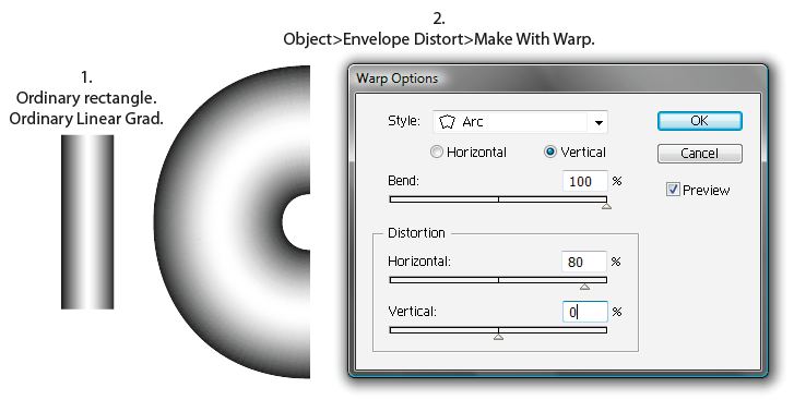
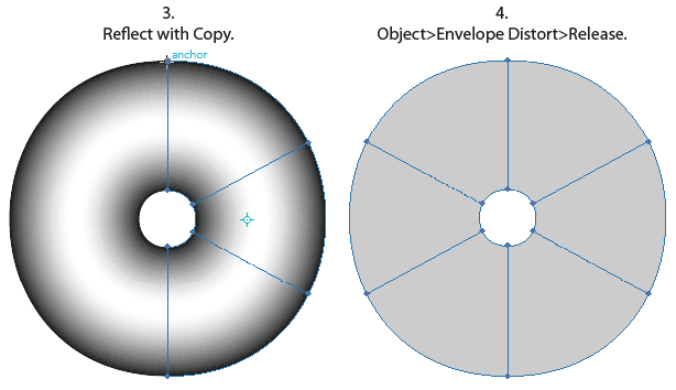
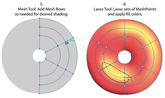
Gradient mesh tool-shaped doughnut-type
Hello
I am using the gradient in the shape of doughnut-type mesh. Basically I want the circle inside and outside donut to be black and the Interior to fade to gray and vice versa. In other words, I want the mest degraded to follow the path. Now I realize that the gradient mesh is unable to do this. So what I did cut my form into four and then try to apply the gradient mesh - still it did not work. I hope that him below will tell you about what I'm doing and what I end up doing!
Thanks in advance for your help
John

Or...
JET
-
Gradient Mesh tool will not work on a standard gradient
How can I get the NET tool to work on a gradient? If I place an RGB image and create a gradient on her net, I can select each individual point, and then use the color picker to select a color below by clicking on the placed image. However, if I create a gradient on a standard gradient mesh I can not pick up the color of the standard gradient which is below. What is the color picker, raise the overall slope. It does not put any color in the different points of the gradient mesh.
Well, you can always gradient rasterize manually by flattening its appearance...
Mylenium
-
Gradient mesh - segments distorted with no anchor points
I often run into a very strange behavior with the gradient mesh tool, where a line segment becomes strongly deformed (bent, looped or with a hard angle in it) has no anchor points or control handles to take account of the distorted line segment. I've seen this happen with the gradient mesh tool. In my last occurrence of this issue, I should be a curve segment gently between two flat control points, and on the contrary, there is this huge "elbow" in what was a difficult angle and almost a loop that has nothing to do with the anchor points. There are has no anchor between these two points (I started with a rectangle and has begun adding and manipiulating points).
Anyone know of what I speak and have a workaround or a solution? Or even an explanation of why this happens maybe make me less frustrated.
t
Meshes sometimes insert points "helper." Switch to the point less tool, then click on the 'assistance' to delete it.
'Helper' points are visible only when the tool Point less is selected. They appear as small, strong, points compared to actual mesh points. Below is an extreme example of the "assistance" points being inserted.

-
Problems of duplication of gradient mesh
Hello world
I have a little trouble with the gradient mesh.
I created a few script letters of which some is attached upward with a continuous mesh snaking around the letters.
The problem is that the mesh shows through parts of itself where it overlaps.
(see image below)

Seems to be poking through part of the mesh.
Any help to know how to solve this problem, or any workaround would be fantastic! As Cup of splitting of the mesh in the individual letters. It's my first foray into the nets of gradient, I have no idea what's going on.
Thank you very much
Pete.
For the sake of explanation:
1 pen. Draw a path that crosses over itself. Solid line, no fill.
2 Appearnance Palette: Add the new Stroke. Give the line added a different color and greater weight and send it to the bottom stroke of origin. You should now have the appearance of a thin "path" effectively "bordered" on both sides of the thicker line color.
Now look at the intersection where the trail crosses itself. Note that there is no "overlap". In other words, even if a path has a direction, and his anchorPoints have a prescription, the anchorPoints and unique (or path) path segments do not have a stacking order in the Z direction (front / rear). In other words, "latter" segments a path of not not 'overlap' segments 'earlier '. They intersect just as two roads intersect at a four way stop; one road is not "pave over" another:

It is similarly transparent traces. Even if more than one subpath can consist of a compound path, all subpaths are at the same level in the stacking order Z:
So it really shouldn't be a surprise that the 'later' end your gradient mesh object does not overlap at the end "earlier". However, while the whole mesh that defines the shape does not have a Z-stacking order, its degraded individual patches are. But you have to understand what constitutes the "end of the beginning" and "end" later Take into account:
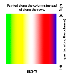
First, imagine a square which is divided into four parcels of the same size. How the program if the two "ends" of this object are to the left and to the right, or up and down?
Second, realize that a gradient mesh wants to divide everything into a rectangular grid. No matter how you end up distorting, the program "thinks" of an object of mesh as a rectangular array of rows and columns.
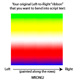
You can view this in a sense similar to the ordinary text. Words are sorted from left to right. 'Later' (in the foreground) is the right word. Suppose you enter a new Word to the left of the sentence; the word most right is always the highest. Now add a paragraph return and type some more. The paragraph at the bottom is the 'more '. If you enter a new paragraph at the top of the textframe, substantive paragraph is always the 'more '.
Think of the columns of stitches from left to right as 'words' and the up and down lines like 'paragraphs', with a warning that "paragraphs" are classified in bottom to top instead of top down.
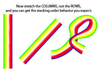
As usual, when confused about a behavior, just a little experimentation with simpler objects you can design to replicate the problem reveals what is happening. Mesh patches are stacked in a low upward (lines), order from left to right:
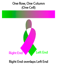
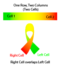
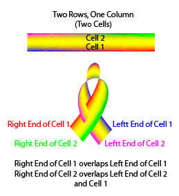
So in your example, you just wait for a column of cells to be quite in the front of the column to the left of it, just because you've coloured cells in a mode of left to right. You're just confuse yourself. You see the "intertwining" of cells of different lines and think that something is wrong. It is not the case. So the solution is simple (although certainly not intuitive). Turn your expectations of 90 degrees:
JET
-
Mesh Hangman plugin works with in Illustrator gradient mesh!
HUGE CLAIM to show the mechanism of this plugin loading in Illustrator CS5!
I did not...
Who knows the loading mechanism on the illustrator of the AIP files?
Get directions how to proceed.
Download the CS5 version
Unzip
Stop Adobe Illustrator
MeshTormentor.aip to
C:\Program Files (x 86) \Adobe\Adobe Illustrator CS5\Plug-ins\Extensions
Start Adobe Illustrator window > MeshTormentor
User Guide
Mesh executioner Adobe Illustrator plugin - complete Guide - Freebies - Vectorboom
-
perspective on the gradient tool. any ideas?
I use the gradient on 3D obects space tool that I drew, I wish I could drag a slider or move an object, and the rest of the case would move with it in any influence of the object instance that I am dragging. However as they are not manipulated.
I could spread the mixture, and then move them, but is there a way to do without developing the mixture?

for now, that the perspective is reversed, it takes less space between the objects from the perspective of what concerns the distance.
So maybe try a different approach - create a brush art or brush of an array of law model and the change once applied. And of course don't forget things like the good old mesh warping or symbols and associated tools, including the perspective grid.
Mylenium
-
How can I separate an object in Illustrator (CC) gradient mesh so that it looks like it is broken, and broken glass? I can take an ordinary object such as a form and cut it out with the knife tool, but it will not work on a gradient mesh. I tried the pixelation, expansion, without success. I also tried to open it in Photoshop and saving with a transparent background and a trace of shadow around her, in the two .eps, .psd, or png formats also without success. If I can do what I want to apply for parts 3D effects. It is a human form and I want "" burst". I need NET gradient to show the contours and the muscles of the body. I am doing something that is not possible? Thanks for any help.
A 3D software will be much better for it.
In Illustrator is possible, but it will be a laborious procedure.


Maybe you are looking for
-
Thunder bird wont let me install a spell check language I followed the steps online but it wont work, I do something wrong? I am pressing Thunderbird announcement then it asks to save / open with when I press open with her ask with what program and I
-
For the second time in six months, Thunderbird seems to have lost all my emails content.
I have Thunderbird loaded on a MacBook Pro. For the second time in six months, disappeared the conent of all emails. I have a list of emails, but the content does not appear in the reviewing pane or if I open the e-mail. I made no changes to the comp
-
If a document pages on iPad 2 Air can be restored?
A document Pages deleted on iPad Air 9.3.1 can be restored?
-
Portege M200 won't start CD-Rom USB
I tried used, pressing C, changing the Bios and F12 boot boot from CD-Rom. None doesn't seem to work, if anyone has any other suggestions I would be grateful.
-
My Acer Aspire 4736ZG stop each time I start and will work in safe mode
This problem has been some time now. Whenever I turn on my computer notebook (Acer Aspire 4736zg) close at boot (windows loading screen) and it really means not freeze SHUT DOWN or restarts... He likes to lose power. It only works in safe mode. Insta