Persistence digitizer/oscilloscope waveform
Normal
0
21
fake
fake
fake
PT - BR
X NONE
X NONE
MicrosoftInternetExplorer4
/ * Style definitions * /.
table. MsoNormalTable
{mso-style-name: "Table normal";}
MSO-knew-rowband-size: 0;
MSO-knew-colband-size: 0;
MSO-style - noshow:yes;
MSO-style-priority: 99;
MSO-style - qformat:yes;
"mso-style-parent:" ";" "
MSO-padding-alt: 0 cm 0 cm 5.4pt 5.4pt;
MSO-para-margin-top: 0 cm;
MSO-para-margin-right: 0 cm;
MSO-para-margin-bottom: 10.0pt;
MSO-para-margin-left: 0 cm;
line-height: 115%;
MSO-pagination: widow-orphan;
font-size: 11.0pt;
font family: 'Calibri', 'sans-serif ';
MSO-ascii-font-family: Calibri;
MSO-ascii-theme-make: minor-latin;
MSO-hansi-font-family: Calibri;
MSO-hansi-theme-make: minor-latin;
mso-fareast-language: EN-US ;}
Is it possible to have the scanners NOR
show waveforms with persistence as benchtop Agilent and Tektronix
Oscilloscopes? I understand ZTec modular oscilloscopes have this function. I have
guess, it can be progemmed using LabVIEW, but is there one out of the way of the plateau of
do?
Thank you.
It is currently not a single property or a function that implements persistence for NOR-SCOPE. Your interest for this feature was placed along R & D for future consideration.
You're right that you can set this feature in LabVIEW. I consider using a graph of intensity. The value of x is your time, the value of is the extent of your blood and you browse your waveform, you must create the z values to show the persistence of the wave. Maj reqisters can be used to track the intensity of the previous iteration.
-Jennifer O.
Product Support Engineer - scanners-high speed
Tags: NI Products
Similar Questions
-
multiplying to power analysis oscilloscope waveforms
Hi guys,.
I'm new to labview. Currently I use Labview 8.5 to connect with Tektronix GST 2024 B osciliscope to calculate the power. I use the example of Labview code (series of tektronix TDS acquire continuous waveforms.vi) to begin with. However, the problem that I ran is that I could not mutiply the waveform of the signal of osciliscope with a test signal (sine wave), I created in Labview. The goal is to test the P = VI mutiplying two waveforms together. Is there a reason for this? If so, how can I fix my program? Can you guys see something wrong with my program in general?
Thanks for your help
I suspect that your problem is probably due to the data type of dynamic signals - use one of the screws to signal generation to generate a sinusoidal shape data type and you should be able to multiply them together. You will need to make sure that they have the same dimensions (for example, length / dt / start time).
Product:
-
I am Setup extended to the acquisition of multiple discs, number of records, set to 50 for 8 channels of 50000 samples. I want to know after 50 triggers received by scope will be stop acquisition or it will start to crush the Chronogram of 0.
I ask this question because everything in extraction of waveforms, I'm more than 100 records, acquisition of data and the scope does not have 50 after triggers, it is waiting for the next release I stop it manually.
Hi Somu26,
What digitizer/oscilloscope do you use?
«I want to know after 50 triggers received by scope will be stop acquisition or it will start to crush the chronogram 0.»
The short answer is that the acquisition stops.
The behavior of the driver NOR-SCOPE is defined and described by the following of Acquisition Envine diagram States-transitions. This documentation can be found in the help file under the heading devices > state diagrams. It is also documented online here: http://zone.ni.com/reference/en-XX/help/370592W-01/digitizers/5122_state_model/
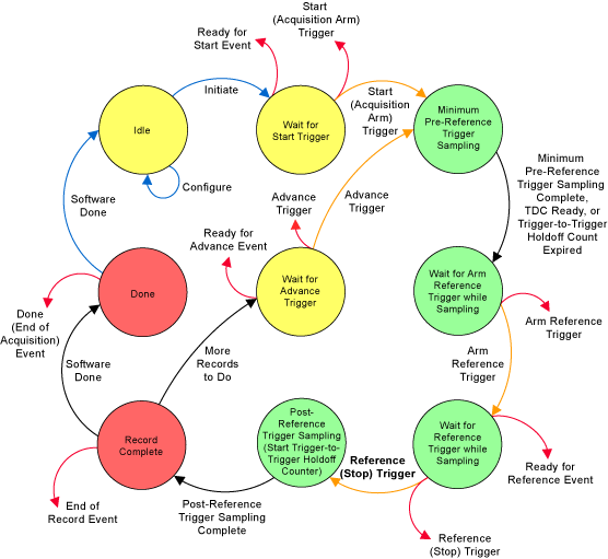
In general, an acquisition ends when all configured samples were acquired. By default, there is only one folder, then when all the samples in the record is acquired, the acquisition to the 'Full record' State transistions, then to the State 'Done '. In a multi-record acquisition setting, the unit will continue to acquire data until all records have been acquired. Once there is no more registration acqure (she has acquired every 50), it will then be transiition as 'Done '.
Note that the Green States that are the only countries in which the data is written in the on-board memory, when an acquisition is completed, no additional data is written to on-board memory, so no chance for the data to be overwritten.
I hope this helps answer your question. I strongly recommend you and any study of customer digitizer/oscilloscope, as this picture of the State, like most of the questions about the behavior of the device (acquisition, trigger, timouts, etc.) can be answered in it.
Kind regards
Nathan P.
-
frequency corresponding problem with myrio!
Currently, I am working with myRIO and Labview 2013 to generate sinusoidal PWM signals.
When I created 'analogue output' tab myRio and connected to the Oscilloscope, oscilloscope waveform could not show me the appropriate frequency combined with a frequency that I gave in labiew. Is there a relationship between the frequency of "the"(myRio tap) of analog input between real-time rate? ". Otherwise, is it certainly possible to calibrate the frequency in labview? Please help me!
-
Need a little help to understand the features of measure or-scope
Hi taurna,
The Stats.vi measure will take a measure through the complete waveform acquired in that particular record. Help on the Fetch Multi steps Stats.vi:
The waveform on the digitizer calculates waveform measurement is to
an acquisition that you launched previously.But according to the measure of the positive width, you see only the first pulse width. The definition of the measure can be found below (note the use of 'first two mi'):
Positive width
C/C++ equivalent: NISCOPE_VAL_WIDTH_POS
The time difference in seconds between the first two mid reference
crossings, where the slopes are positive and negative respectively. A
Digital hysteresis is used to find the points.Help on the num in the statistics section:
Num in stats returns the
number of measurements to calculate the statistics.Saying "1" here, he did a single measure on your single purchase you took, since the while loop was taken out of your code. If you want several measures to make, you need several acquisitions.
-
How to build a parser of vector signals PXI using different module combinations
Normal
021
fake
fake
fakePT - BR
X NONE
X NONEMicrosoftInternetExplorer4
/ * Style definitions * /.
table. MsoNormalTable
{mso-style-name: "Table normal";}
MSO-knew-rowband-size: 0;
MSO-knew-colband-size: 0;
MSO-style - noshow:yes;
MSO-style-priority: 99;
MSO-style - qformat:yes;
"mso-style-parent:" ";" "
MSO-padding-alt: 0 cm 0 cm 5.4pt 5.4pt;
MSO-para-margin-top: 0 cm;
MSO-para-margin-right: 0 cm;
MSO-para-margin-bottom: 10.0pt;
MSO-para-margin-left: 0 cm;
line-height: 115%;
MSO-pagination: widow-orphan;
font-size: 11.0pt;
font family: 'Calibri', 'sans-serif ';
MSO-ascii-font-family: Calibri;
MSO-ascii-theme-make: minor-latin;
MSO-hansi-font-family: Calibri;
MSO-hansi-theme-make: minor-latin;
mso-fareast-language: EN-US ;}Normal
021
fake
fake
fakePT - BR
X NONE
X NONEMicrosoftInternetExplorer4
/ * Style definitions * /.
table. MsoNormalTable
{mso-style-name: "Table normal";}
MSO-knew-rowband-size: 0;
MSO-knew-colband-size: 0;
MSO-style - noshow:yes;
MSO-style-priority: 99;
MSO-style - qformat:yes;
"mso-style-parent:" ";" "
MSO-padding-alt: 0 cm 0 cm 5.4pt 5.4pt;
MSO-para-margin-top: 0 cm;
MSO-para-margin-right: 0 cm;
MSO-para-margin-bottom: 10.0pt;
MSO-para-margin-left: 0 cm;
line-height: 115%;
MSO-pagination: widow-orphan;
font-size: 11.0pt;
font family: 'Calibri', 'sans-serif ';
MSO-ascii-font-family: Calibri;
MSO-ascii-theme-make: minor-latin;
MSO-hansi-font-family: Calibri;
MSO-hansi-theme-make: minor-latin;
mso-fareast-language: EN-US ;}I understand
Vector signal analyzers OR consist of 2 or 3 separate PXI modules: 1
digitizer, 1 buck converter of RF frequencies and 1 generator of signals (model 5663).1. can I use digitizer and signal
generator general purpose oscilloscope and generator of signals separately?2 may I build my own VSA by choosing
different combinations of scanners and the signal generators? Or replace the signal
generator by an arbitrary signal generator?3. I
intend to buy a digitizer/oscilloscope and an arbitrary signal generator
analysis of response of frequency on the transformers. Later I plan to
buy a step-down converter frequency and build a vector signal Analyzer. Is this possible?Hello
The frequency IF the 5660 and 5661 (it's the same thing) is 15 MHz, with an instantaneous bandwidth of 20 MHz. The difference between the 5660 and the 5661 is located in the digitizer that accompanies it. The 5660 uses the PXI-5620 digitizer that has a sampling rate 64 MECH. / s and a buck converter of digital frequency limited to 1.25 MHz of bandwidth. The 5661 uses the digitizer PXI-5142, giving you a MECH 100. / s rate and a PSO allowing digital downconversion circuit and the decimation of the full bandwidth of 20 MHz.
The common comment in the SBA above is the RF PXI-5600 frequency step-down converter which is a superheterodyne architecture of three floors. OL is for the three stages of this module are auto-approvisionnées in their own country. The architecture of several step allows for rejection of the improved image and filtering at the expensive of a noise floor slightly higher due to the signal path more complex. There also an OCXO on board, this gives him a time reference more precise - noise reduction phase etc. The PXI-5600 by itself is wide from three locations.
The SMU-5601 since SMU-5663 step-down is designed based on the single frequency step-down converter and resumes from a single location. The celled frequency step-down converter gives you improved noise floor characteristics and a better dynamic range, with the rejection of the image fees, having does not simply because there is only one step. The LO is provided by an external module in this case for several reasons. Have a separate external LO allows more modularity in your system, as well as the ability to share a single LO generator between several vendor-specific attributes. This opens the possibility of MIMO applications. The internal of the NI PXI-5600 LOs are not shareable and therefore cannot be synchronized between several PXI-5600 s. The PXI-5663 (all three modules) takes up the same amount of space in the slot as a single NI PXI-5600 without a digitizer.
The PXI-5154 is indeed a powerful scanner, given its instantaneous bandwidth of 1 GHz. Remember, however, that the connector Active Directory on this digitizer is 8 bits, compared to the 5622 which is 16-bit. If you need more resolution is of course entirely depends on your application. The PXI-5600, as SMU-5601 is controllable as a buck converter stand-alone frequency using the DAMA API OR. You will need to program your application with the scope API for use with PXI-5154 OR and the API de DAMA. A few other caveats to note is that there is no PSO on the PXI-5154 so you can't enjoy the Equalization filter to correct the frequency of the NI PXI-5600 response. Also, as I mentioned above, the frequency of YEW of the NI PXI-5600 has 15 MHz with a bandwidth of 20 MHz - processor 1 GHz bandwidth on your digitizer will be somewhat of an overdose of the IF signal.
While you're dead on with the advantage of modularity, I would take the time to really meet your search application and ensure that different choices of module and their combinations to meet these needs.
Hope that helps!
-
Disagreement of Tektronix TDS 3000 VISA and pilot
My lab is trying to use LABVIEW 2015 in order to obtain numerically a 3054 Tektronix TDS Oscilloscope waveform data. We have (on two separate computers) installed the latest version of VISA (15.5) and the Tektronix 3000 series drivers. However, when we open the instrument control drivers and run one of the examples, we get the following error
"Error 1073807202 occurred in opening VISA to Tektronix TDS 3000 Series.lvlib:Initialize.vi-> Tektronix TDS 3000 Series Auto Setup Waveform Acquire.vi"
We have reinstalled the drivers on both computers with no luck, the error continues. We have also re-installed VISA, but the error persists. Is that what could be missing regarding how to actually set this instrument on the rise and synchronize it with labview? We connect the oscilloscope to our computers using a GPIB to USB cable and systems are more or less insensitive.
No indication in this regard would be appreciated,
Thank you
If you use GPIB, you must also have installed NOR-488. 2.
Ben64
-
The sliders are not preparing for the right place
Hello
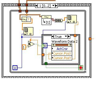
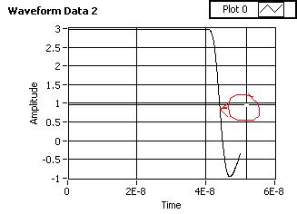
I'm the Agilent MSO7000 series oscilloscope waveform capture. I created waveformdata for one oscilloscope channel and trying to place cursors using the node property of waveform data slider and I see that he is preparing in the wrong position, as shown in the pictures below. I would like to know what is the reason behind all this.
You can see that the cursor is after the position where it should be.
Thank you
Kind regards
Sailesh
Looks like the x axis offset is not applied correctly. If you explicitly set x 0, things look better. I'll study a little more...
Here's a quick rewrite with the same functionality, but including the x 0 problem.

-
How can I get more decimal point.
When I arrived to retrieve the oscilloscope waveform data (model TDS5104), I want more decimal point.
for example, scope out a point that print is 1.5214mV, but I get the point which is 1.52 by labveiw progr.
How can I get more decimal point.
I used an attached instrument driver.
Thank you.
The waveform is DBL, so internally, there a lot of resolution. The number of displayed digits is just a cosmetic property and can be freely chosen.
How can you say that the resolution is lower? I can't say the VI you have set. If you want more numbers representing scale Y of the graph, simply change the formatting.
-
Save the digitizer and DIO waveforms in a single spreadsheet file
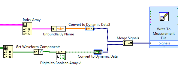
I use mixedsignalscopeusingtclk.vi attached data acquisition and want to acquire 4 channels of data. My system PXI-1042 PXI-5122 and PXI-6552, and I use 2-channel digitizer and 2 digital i/o channels. I'm using Labview 2010 SP1. The VI generated table 1 d of the cluster for an analog waveform and table 1 d of digital waveforms. How to save the two waveforms on a worksheet?
Hello
You can use a write file express VI measure. Note that this is the easiest but not the most effective way to write to a file.
Since you have the extraction screws inside loops, your output is a table 1 d of waveforms. You will need to obtain the wave form and convert it to a type that can read the express VI. If ungroup you the waveform and retrieve only the data and connect directly to the express VI, LabVIEW will automatically place a block of "Convert to Dynamic Data" online to make it compatible. This also applies when you connect the Boolean matrix at the entrance of signals express VI. And if you connect more than one signal to this entry, LabVIEW will automatically place a block of "merge signals."
If you reproduce the code below, you should be able to write both channels in the same measurement file. If you have more than one channel of each type, you can enter multiple items using the same table Index block and take them through the same process shown below.
I hope this helps.
-
are there different scales of two waveforms of the oscilloscope
Hello
I am writing two waveform on the oscilloscope. But one of the wave are very small scale.
Y at - it any wave of scale are two on the graphical indicator of waveform so that the small signal can have higer resolustion?
Thank you!
Hi tian.
Seek the help of LabVIEW for 'scale double y"...
-
Question of timebase NI PCI-5154 digitizer drift
Hello NOR all awaits them:
We have a NO-PCI5154, used for several years now. We use it to capture waveforms of impulse which we care about timing relationships.
We operate the digitizer to sampling of 1 GHz and up to today, we assume the sampling rate is precise and constant. Today, a member of group doubt that since the digitizer specfication said, what the time base drift on "±7 ppm / ° C". So if this is true, suppose we have a Temperation of exploitation that is 20 degrees higher than the temperature at which the scanner has been calibrated, then the derivative can reach up to 140 ppm time 1 GHz which is 140 KHz? It would be a killer of our measures.
Please help clarify this question, then we can estimate errors in our measures.
Unfortunately, we have no data on the repeatability of the time base drift.
To calculate the frequency of real-time database, simply reverse the calculations that we've discussed so far. Measure a source very precise on the digitizer, and any change in frequency of the signal would be caused by the non-ideal time base period.
For example, you measure a signal from 10 MHz to 1 GHz, and its frequency is reported as 10,001 MHz. So, we're out of 1 kHz. 1 kHz = 10 MHz * Xppm, solve for x: X = 100 ppm. Thus, our sample clock runs at 100 ppm. 1 GHz * 100 ppm gives us a period of 0.9999 ns or ns 1,0001. As our frequency has increased to 1 kHz, the signal was compressed when being interpreted to 1ns dt. Thus, the real clock period was 1.0001ns.
Because it sounds like you can't control the temperature of your work environment, to the more specific measures that you can measure the time base clock drift immediately before and after taking your measurements. If you have run your tests in a controlled temperature environment, you might be able to get away with a measure not time base clock drift as often, but you should always run regularly. The reason for this is also due to the effects of aging of the time base oscillator (affects all oscillators). The accuracy of all the oscillators gradually drift or increase over time. Our specifications, take account of this drift in the external calibration interval, but if you're going to measure the actual accuracy, the time is another factor that will affect the accuracy of the time base.
For completeness, I also need to say, that when you measure your test signals ppm accuracy, this shows absolute precision, not only the accuracy of the time base, but also the accuracy of the source of the signal. So it is very important to have a precise source for the test signals.
I hope this helps.
Nathan
-
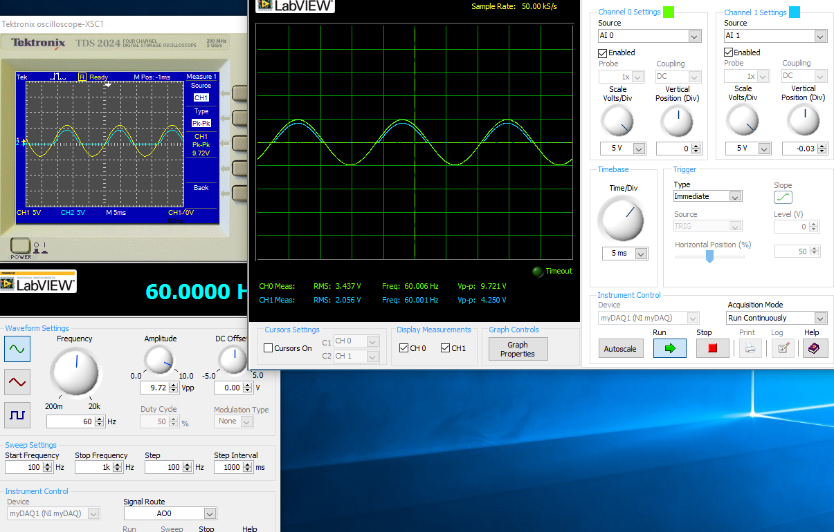
Waveform of Agilent DSO5054A read problem
I'm reading signals oscilloscope with LabVIEW, but when I read the waveform, instead of the real tension, numbers ranging from 0 to 2000 ~ appears in LabVIEW VI. When I change the position of the wave on the oscilloscope, these figures are also changed. Please check the picture below. Are there settings I'm missing? Tensions on the scope are about 5 volts. Help, please.
Hello
You are using the wrong driver.
Try
http://sine.NI.com/apps/UTF8/niid_web_display.model_page?p_model_id=10028
Curt
-
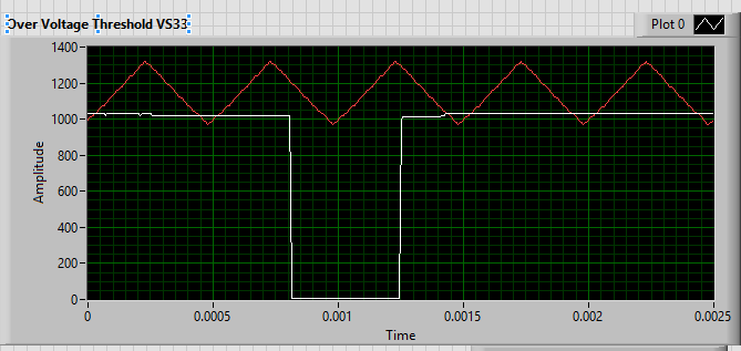
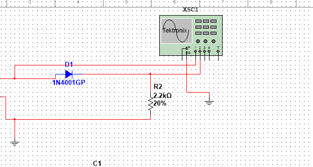
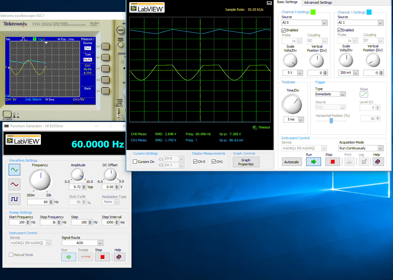
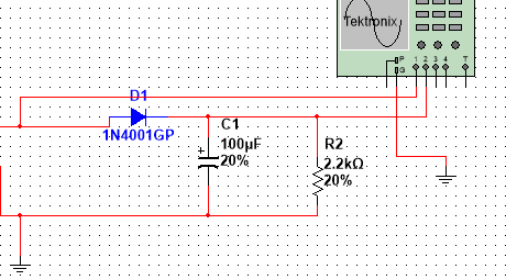
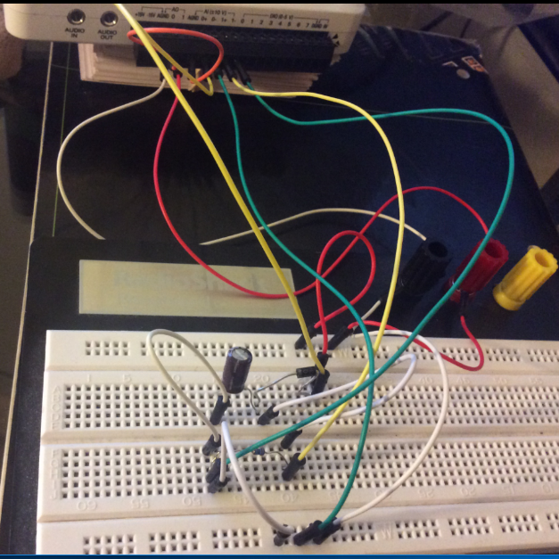
half-wave rectified filter circuit/oscilloscope measurement
Hello everyone, I hope I can get help on this fundamental issue, I'll have. University online, with which I will not help me, so I hope that I can quickly get assistance here.
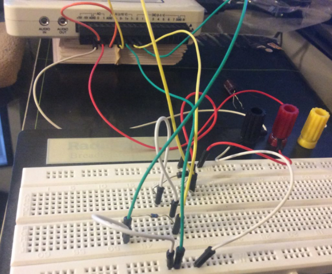
I have the myDAQ NOR, I have to build half rectified filter circuit with a resistance 2.2kOhm, I also use the multi-sim to confirm the measures of waveform. Everything goes well on Labview multisims Tektronix Oscilloscope compared to before I connect a capacitor 100uF my comparison heres:
The model is just the Diode with a series resistance 2.2kOhm, I'm not sure if the analog inputs to the LabView Oscilloscope are configured correctly this is the air I get:
This satifies my simple comparison on the Multisim circuit, since I came here for a few hours to play with probes analog input, I know that something is wrong out of these measures, I get.
With a capacitor 100uF in parallel:
I think the question is how I inputs analog and STILL plugged, I'm not sure that this is where I would really like some help or any type of assistance. Once I get this set up right, I'll be able to take measures for the frequency, load DC, P - P Ripple voltage ripple and then move to a full-wave rectified circuit. I just started a course and received the myDAQ.
Henrik_Volkers wrote:
Compare it with the current specification of output of your myDAQ
Here is a link to the specification: http://www.ni.com/pdf/manuals/373061f.pdf
Henrik hit it on the head. The myDAQ can, at most, out 2mA with analog output. So, with a 2.2kOhm charge, which puts you in 4.4V without the diode. The led will also require an amount of current. According to my estimates, subject of 1mA (your pic is ~2.5V, divide by the 2.2kOhm to get ~ 1mA). You will see only that on the positive side of the sine wave as the diode blocks all the negative side.
The lesson here is to make sure that your outputs have enough power to do what you want. You can go to get a simple op-amp from digikey and use a follower of tension for editing the current upward. You will probably need another power supply or two (+ 12V and - 12V) to power op-amp.
-
I need to connect the two channels of my digitizer for 8 seconds.
I need to see how 2 waveforms (both 350kHz) change hours additional sampling rate should be as high as possible.
Nothing complicated to do.
No trigger. No timetable. No special file type. Files should even be indexed.
Just click. Newspaper. Save the file manually.
What is the simplest way to do?
We have a bunch of software OR (Labview Signal Express, ect..), but no not team knows how to use them...
Thank you very much!
Randy
Yes, I found the option to set up the device and that solved my problem (sort of).
But these files are huge and difficult to treat.
I found a MUCH easier solution - SignalExpress.
In my case, the ultimate goal is to measure the real power of an Electrosurgical generator.
Registration of RMS values for both digitizer channels is more useful then the waves themselves.
SignalExpress allows you to do both quickly. Nothing complicated.
Then, I need to take into account the signal conditioning (down the voltage), I can then use SignalExpress to apply formulas for RMS values.
Bottom line for beginners like me:
Expect to invest tons of time understand nor software and system.
Even for the BASIC things as measurement and recording, the voltage is a nightmare.
NEITHER is really for people who build complex systems.
Here's my advice for anyone to start:
1 use the software of the device you call first to see if it can do what you need to do.
2. use SignalExpress to extend the functionality you need.
3. use LabVIEW if you need even more features.


Maybe you are looking for
-
Replacing the battery of Qosmio G30-204
Hi people, the current battery I have takes about 10 minutes after full load.So, I think to replace. The battery I have right now is a PA3475U-1BRS. I can get my hands on a replacement but the model is:PA3476U-1BRS It is the same shape and everything
-
Hi guys! :-) I need help. I have read many articles and the HelpDesk here, but I couldn't find a solution. Well, I have a Microsoft Account and a Skype account. I would like to connect them with eachother. I know that the official solution: connectio
-
Connection Satellite L555 old Emerson TV
Is it possible to connect my laptop L555 an old Emerson TV? Appears the laptop computer has a VGA output port and the TV has S-video & S-Audio ports separated?
-
Is it possible to upgrade the Satellite A100-906 with 160 GB 7200 RPM HARD drive
Hello guys,. First of all, I would like to congratulate all the people here for their good advice.As for my question, I want to upgrade my HARD drive. I have the laptop A100-906, which has a drive HARD 100 GB 5400 RPM Hitachi. The hard drive, I would
-
630 HP: hp630: possible install ssd?
I think that to replace the HDD with ssd, but I can't find in the BIOS set up how to choose the option AHCI So: it is not necessary, and in any case the ssd will work correctly in TRIM mode? or there is how to define the new configuration mode? I thi