Problem DAQmx Read or PDM
Hello
Recently, I changed a series of Structures of cases in a more efficient Structure of the event. However, I'm no longer able to acquire the 4 analog inputs (OR-USB6251) terminals voltage signals with DAQmx Read and store them in a TDMS files. The code responsible for this task 8 ('start running Scan') is the event of the attached code structure.
At first I thought I was calculating the 'timeout' or 'number of samples per ch' incorrectly. However, even when I put them to contant, great values DAQmx Read doesn't seem to work and as soon as the program TDMS files Viewer is empty. One thing I didn't change was moving TDMS close in the Structure of the event when he was outside of the big loop previously. Could this be doing me wrong?
Alfredo
Hello Alfredo.
Of course you have a lot of code here. When you close the TDMS reference in your loop, the next iteration of the loop will be an invalid reference and so nothing will be written to file. Be sure to always close your references outside of your loops.
Tags: NI Software
Similar Questions
-
Hello
I use DAQmx Write (Bool digital 1Line 1 point) to send a Boolean sample to a digital output channel. I want to be able to tell if the signal is strong or weak, so I use DAQmx Read (Bool digital 1Line 1 point) to take up the task as input and then plug a light at the end of data. The problem is the light lights up when I pass False to the VI DAQmx writing and does not shine when I pass the value true to the writing DAQmx VI. Shouldn't the DAQMx Read VI be output Boolean even as input to the VI DAQmx writing? In others, should I not get a true reading VI DAQmx if I pass a real in the DAQmx writing VI and even for a case of false?
See code attached for simplified example of what I'm trying to do.
Thank you
Jason
Which would make sense if the channel is configured as an open collector output. This would mean that the line is retrieved when you write a REAL low and left floating when you write a FAKE.
-
Error 200088 using the DAQmx reading VI in a case structure
Main problem: I'm writing a VI that will read data from a data acquisition and write to a text file when I hit a button "registration". To do this, I use the VI of reading DAQmx in a while loop, which is located in a case statement (I hit the 'Save' button for the case of true), which is in another while loop. My DAQmx create Virtual channels screws are outside of the loop, so a wire goes through three structures to connect these screws to the VI DAQmx Read.
After clicking on 'Save', my VI works until I hit the "Stop" button, how I get error 200088: ' specified is not valid or does not exist. " If anyone can help me get rid of this error, that would be greatly appreciated!
I enclose my VI and an image of the error.
Secondary problem: currently, I use two different DAQmx read live: one mentioned above, which lays down: after clicking 'Save' and the other who reads data continuously to display on maps. I want to combine these two, but I don't know if this is possible given the case statement.
Thank you!
Hi Alexwright,
I made some quick changes to demonstrate the producer consumer loop that would be effective in your case. You want to loop of producer in the first while loop so that you use and the same closing DAQmx task. Moving a forwardthis will require some trial and effective change for your application. Please also make sure you use our debugging tools: http://www.ni.com/gettingstarted/labviewbasics/debug.htm.
I hope this helps.
-
DAQmx read - the values on the scale or not? Binary conversion.
Hey everybody,
I had a question regarding making the scale and the release of Renault. I use LabVIEW 2009 SP1, with a pilot DAQmx 9.0.2 and a X-Series card. I'm reading the data my DAQ and store it in a binary file.
How is the acquisition of data read samples, in General? that is if I select NSamp NChan I16 2D Analog on my DAQmx Read, what kind of values can I expect if I was at the exit of the probe data? (Suppose I have readings in mV values and my overall fork's 04:55 V.) When he wrote in the binary file, what happens, what can I expect to see in terms of values - or maybe just descriptively?
Overall, a little insight would be very helpful. I tried to troubleshoot asymmetric readings I received, so this will help me immensely.
Thank you.
Hi Matt87,
Reading data as I16 will return the result adjusted, not calibrated for 16-bit ADC.
If you want to write your own binaries, you'll want to include scaling of device - for series X, coefficients a 3rd order polynomial.
Here are two examples that show how write to a binary file and read the data back. In this example, scaling coefficients are stored in the file header:
Continuous gain and voltage drop (binary) chart
Graph of the acquired binary data
That said, I would recommend that you look in the record feature integrated TDMS introduced in DAQmx 9.0. The result is a file appropriate binary .tdms which is a standard format that can be opened in LabVIEW or in several other programs with the plugin. See the following examples for how to use the function:
Streaming data and log to the PDM file
Continuously to log in a PDM file data
The second example does not force you to read the data in the memory of LabVIEW and use the minimum CPU. The first example allows you to see the data that is acquired.
Best regards
-
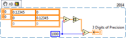
Change the precision of the waveform data or daqmx read
Hi all
I am currently using daqmx read and write data to a PDM daughter. I would change the precision of the data if possible.
Any advice?
Thank you
Matt
It is important to get the right information in the data file. It is not a lot of overhead to limit your data with a specific precision if you as a table.
I don't know which is faster, the method of accuracy of the channels or this:
It took 1-2 ms per 1 million iterations.
-
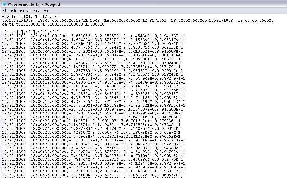
Timestamp problem DAQmx waveform
I have a program that reads analog signals multiple DAQmx using a PFI trigger from a DIO card to start the acquisition. It uses a registry to offset and Boolean logic to stop the DAQmx read the loop when the trigger is low. I traced the result to a curve of waveform. I have a 1000 S/s scanning speed. I traced the data to a graph of waveform and eye on the individual data points and it is perfect. Exactly 1 S/s. The problem: when I increase my 5000 S/s scan rate... I see exactly 1 S/s, but the displayed duration of my test data is 5 x more time. That tells me that my graph of the waveform is plotted in fact each data point individual 1ms apart. So basically, there a 1ms all dt in the waveform, and it does not change. How can I get the real dt of the analysis of data here instead of this arbitrary constant? When I look at a text of my waveform data file, I see the timestamp below where I'm expecting something ending like that... 0,0010, 0,0017, 0.0025, etc.. Any help would be appreciated. I'll post the VI if necessary, but other than the trigger power, is a fairly straightforward HERE DAQms read. Thank you in advance.
The time of LV start date is January 1, 1904 midnight GMT. Since your shows up to 6 hours before that, he must be GMT - 6. My horodateurs base are 19:00 31/12/1903, which is GMT - 5. Eastern time zone.
Are you any error coming out after your Subvi waveforms?
You empty an array of waveform data to add. The default waveform has a T0 zero and a detachment of the 1. In the Sub - VI of waveform append inside your Subvi if dt' it does not raise an error, (in fact a caveat being the 1802 error code is positive.). But she proceeds to add data and use the dt and T0 the first waveform which is initially as the default data in the initial iteration. I think that if you start with an array of wavefrom that has the number of channels of the need, an empty array of Y, but a correct dt. Then the dt should be correct. That, or you can put in your Subvi a case structure where the first call, or if the incoming waveform is empty, it is not add and uses only the 2nd waveform.
You have also a little a Rube Goldberg enters your Subvi. It could be simplified as shown in the picture as an attachment.
-
Get error-200088 DAQmx reading (Analog DBL 1Chan 1Samp) .vi < add >...
Hello
I am using examples of labview and Labview 2011, I use the a sample.vi acq for the value of the voltage reading.
but the thing is that I get the error of block then read this DAQmx Read (Analog DBL 1Chan 1Samp) .vi - 200088
... And it's not indicate the correct voltage in labview. I also connected Multi meter with the analog card reader and multi meter gives the correct value, but it is not possible to achieve with labview.
Please guide me how can I solve this problem which could be the reason for this.
Thank you very much.
-
Why DAQmx read 200714 error when you save the file?
In particular vi that I created, I have 3 analog inputs coming in and are graphically represented. If I choose to save the information to a file, a dialog box appears and I can choose what to save it under. If I take too long to save the file (aka about 8-10 seconds if the sample read rate is 500/s) then I get this error once the file has been saved:
Error-200714 occurred at .vi DAQmx Read (analog 1-d NChan DBL 1Samp)
Possible reasons:
Acquisition stopped because the driver could not transfer the data from the device to the computer's memory rather quickly. This was due to limitations of the computer system.
Reduce your sample clock rate, the number of channels in the task, or the number of programs on your computer that is running simultaneously.Why the DAQmx bed vi I have this problem when the vi has been idle for 10 seconds then I choose where to save the file? How can I fix this error?
Hi child of pre-school age,
I think your error might be caused by the read buffer overflow. my suggestions for you would be to either the following four ideas:
1. stop the acquisition before writing the file. This should mean that the DAQmx Read function will no longer be reading and therefore does not generate an error.
2. If you still want to read the data but also write data as well, I think you'd be best suited for use live TDMS. TDMS allows the user to stream to a reading of filewhilst.
3. the configuration backup dialog box file before starting the acquisition. Download the user to enter all data in the file before you start to acquire.
4. change the buffer to unlimited so that you have enough time to navigate the record window.
If you send your VI I can advise others
Let me know how you go,
-
analog parallel DAQmx reads at different rates of acquisition
I'm running two 9172 chassis with a total of 11 modules. I have two 9217 modules for reading RTDs and a 9205 for sensors of reading level. I've set up three spots, one for each module.
If I do a task sheet and place DAQmx Read in a loop, I can read all the data without problem, but the three tasks take 4.59 seconds per iteration (reading the RTD is seems to be slower). I need to update the level readings more Rapids, but if I do two parallel loops, try to read the RTD in a loop (two tasks) and the level in its own loop sensors I get an error that the resource is not available - apparently only one instance of DAQmx Read can be called both.
Is there a work around for this?thanx
lmd2Larry,
Your problems are all related to the task that is described in the manual DAQmx State model. Each 9172 chassis can have 1 HAVE task that runs at a given time. If you try to start a second task, you will get an error. When you use the loop FOR your code is starting and collapses of each task in order that takes a lot of time and explains the 4.59 seconds. Ideal for config and start tasks in an init State and then begins to acquire data. The only thing left to do is to release the input/output by stopping and disabling tasks when you did.
One way to solve this problem would be to install two RTD modules in a single chassis and all 9205 modules in other chassis. Another way would be to oversample of RTD and process the additional data later.
-
I tried to import my vcard to icloud, which is in format .vcf. It is projection 300 contacts could not be imported because there was a problem to read. What should I do to import them.
You could try to export your contacts into smaller groups
-
Problem with read/write satellite U400 - 12 p PSU40E DVD on LG GSA-U10N
Hello again,
Another serious problem is the LG GSA-U10N DVD combo drive that comes with mine U400. For some reason he has serious problems with reading and writing to DVD. Doesn't depend on whether the media is expensive or cheap. It seems to read and write all the CD very well, however.
I would like to avoid leaving service point (can take up to 3 weeks or more), because I need this laptop all the time.
Is there anything we can do about it?
My system - Vista Home Premium 32 bit has been restored to factory default and then fully update the site of microsoft, outside pilots. In addition, no other movements driver update has been made. It's just that you want it to be.
Greetings
> Doesn't depend on whether the media is expensive or cheap.
Not reallyMy notebooks drive can handle a lot of different CD and DVD from different manufacturers, there are cheaper and more expensive DVDs.
I had a good experience with TDK DVD-R discs. In most cases, the burning procedure could be completed successfully
But I had some problems with the other DVD writing.I think the whole issue is compatibility between the laser lens and DVD-surface and that's why I recommend you several DVDs from different manufacturers.
Goodbye & good luck
-
Problem to read the details of the new widget news
I'm having a problem of reading new news of the widget. Maybe someone could help me.
When I click on the title of a news article, it opens the browser, seems to go to the site news.qwapi.com and returns an erros indicating that the site is currently unavailable. Things seemed to work fine until a few days ago and I did not recent changes that I'm aware of that could be the cause of this problem.
It happens not all the press articles, some successfully opened on Reuers, etc..
Did anyone else encounter this problem with their Cliq XT?
Concerning
I had the same problem this morning, just removed and added the widget to the home screen, and it worked fine afterwards.
-
I am still fairly new to LabView, only it uses about 5 months, so bear with me.
I'm trying to understand why the DAQmx playback function runs slower I expect. I use a PCIe-6363 map connected to two BNC-2110 connector blocks. I run the attached code (Position AOM control_prod_cons) and producer while the loop takes about 14 ms to execute. Here's why this is a question:
The Subvi belongs to a larger structure that we use in our research lab to run our system of construction craft nanofabrication. You are using a computer-controlled turntable (wise move task), monitors of reading of the scene (spot monitor sensor) sensor and control a shutter that controls power to the sample (Subvi with lightning) laser. Up to 4 outputs analog and three analog inputs. The scene is being ordered to move in 5 steps of nanometer to a speed of 50 micrometers per second, a rate of analog output of 10,000 samples per second per channel (3 of them). The shutter has a rate much more low yield, at most 5 samples per second. Our goal is to synchronize the movement of the scene with the shutter, and so we must read the exact position of the scene using the analog inputs, one for each axis, x, y and z, vote as often as possible, even if in reality it didn't need to be more than one read each ms.
AOM control_prod_cons position takes two points in space that we wish to move between two points where the shutter must open/close. The first image in the flat sequence did some vector calculations to get the line that we write out the origin of the octant where x, y and z be positive by adding or subtracting, then making reflections around axes, if necessary. The end of x, y and z values (which are now all positive) are summed and placed later in the sequence. Coordinated sensor monitor are then read in (loop producer) and turn the same way coordinates the target have been transformed (consumer loop), then compared with the values of (x + y + z) end and start (0) and adjusted accordingly shutter. (For troubleshooting purposes, "off" is 2.5 and read the text file we entered to extract structure).
All the tests I've done so now tell me that the loop of the producer is the rate limiting step. For a line that is 30 microns long, with the displacement of scene I described above, I was 45 or 46 readings, that works on a read (on the three channels) once all the ~ 14 ms, or only 72 samples per second per channel, which is * very * slow for the card and is not acceptable for our application. Am I missing something? Why the producer loop takes 14 ms per iteration? I tried to reduce the sampling frequency of writing to 1000 samples per second per channel, but that did not alter the reading rate, so I'm not sure I can cela pins on the map.
I ran the DAQmx read function as a NChannel 1sample, read in a while loop like I do in more complicated VI, reading of the three analog inputs in a very simple VI who only reads the sensor monitors and nothing else and the reading rate was 2750 samples per channel (read 5000 samples through three channels in 1800 ms) , so I know that the card can read that fast.
I've also attached the highest lying VI that sets up the physical channels for adding information. I am also attaching a VI where the producer/consumer framework is not used. Also, this while loop took ~ 14 ms to exploit.
Sorry, that was so verbose, just try to do what I'm trying to erase. If you have any other questions, please just ask. Thanks in advance for your help.
Well I'll be darn. The "task AO is?" query seems to be the culprit. I have no memory of being always aware that there was such an expensive application. I don't know if I tried to make such a request in a tight loop before, but I'm a little surprised by the fact that I'm surprised. I don't know if anything is changed, but in case it's a secondary-ish effect, I use the new DAQmx 16.0
Another approach would be to use a property DAQmx writing node to query the Total number of the samples. It seems quite a bit faster.
-Kevin P
-
I have a question about the order of execution. In the WHILE loop, I have two things to measure, period and tension using the DAQmx READ functions for voltage and the meter. In the end, I want to collect these data as points almost simultaneously as possible, as a pair and then send them together to another piece of code (not shown here) which them will result in some sort of command for an engine. It would be run, and then I want to perceive the tension and the period at a time later and do the same thing.
(1.) I'm a little confused on what the meter of the READ function is back because it's a table. What is a picture of? I thought that it was up to the value of the individual periods between rising edges. The output of the counter 1 DBL d's a table. How many elements in this table, and what determines the size of this table? Are the elements of the array the individual delays between the edges? How many values are stored in the array by executing? We take the AVERAGE of the last 15 items, but do not know if we are throwing some of the data or what. How to understand the composition of this painting? How can I change the composition of this painting? Is it possible to measure only one period at a time, for example the time between TWO edges?
2.) Will this WHILE loop execute as it gathers tension and a "period table ' (remains to be understood by me) by TIME running in a loop? In particular, we want that the value of the tension associated with the value of the AVERAGE of the period "array", so we can use two data items to create orders of next control every time that the two values are reported. The structure for the delivery of vi will be attached data in pairs like this? I understand that one of the READING functions run not before the other function of READING in the WHILE loop. I want that the period "means" and "strain (Volt) collected at the same pace. This vi will he?
Thank you
Dave
Hi David,
I suggest including the DAQmx Start Task function. If it does not start before the loop, it starts the loop and work very well, but it is not as fast and efficient. In the model of task status, task wiill go to run the checked each iteration of the loop and then back the time checked running when it restarts.
The status of the task model: http://zone.ni.com/reference/en-XX/help/370466V-01/mxcncpts/taskstatemodel/
Kind regards
Jason D
Technical sales engineer
National Instruments
-
Another that the convenience of the format of the data acquired, are there benefits (e.g., memory, speed, etc.) usage
DAQmx readout 1 d Wfm NChan NSamp
-Or-
DAQmx read analog 2D DBL NChan NSamp
I'm a life-long in multiple buffer
channels using an architecture of producer/consumer. I am not concerned by information in absolute time available in the format of the wave form; It is convenient, but I can get what I need also. In post processing of the data, the format is a stack or face. If I collect the Wfm 1 d data I end up stripping to the Y-data for certain analyses, but eventually the construction of waveforms for the analysis of the other if I collect a given 2D DBL.-CTF
I did a quick comparative analysis and it seems that the WFM D 1 is slower and takes more memory than the 2D DBL. The overall impact of these differences depends on the size of your data blocks.
Maybe you are looking for
-
How can I change the web page by default when I open additional tabs?
My home page is set to the default normal page but when I open additional tabs a Yahoo page opens and I don't use it and don't want to do anything with it. I used to get the search page Google/MOY. This only happens when I open additional tabs. So, h
-
Reset Windows Picture and FAX viewer as the default value for jpeg files after loading of Corel
I put Windows Picture and FAX Viewer by default to open jpeg, tiff and other pictures, so it appeared as an option in the drop-down list to view attachments that have been downloaded. After loading the software Corel Draw, it is now the only option t
-
How can I fix the blue screen? / Lvl4 file... DISP (missing or corrupted) / I have Window XP SP3
When I work on my computer some as many times as this happens shoutdown and I don't know what to do. My graphics card is a Geforce nvidia series 8400GS./512MB/DDR3. This problem started after the installation of this video card. (Two months ago)
-
I have a hp 5510. It is only printing pink. I changed my ink, its all good new ventilated, cleaned & aligned printer always pink. I'm out of ideas. Help, please!
-
Error Message Oxc18a0206 ink system failure Photosmart C6100
My operating system is Windows 7, and my computer is a Dell studio. I did no hardware changes or software before getting this error message appearing a week ago. Thanks in advance for your help.