Problem with PXI SMU 4132
I have observed 4132 PXI is sometimes load dependent. We were testing a specific device
which is part of the bi-directional and when we forced a current through the device in the negative sense of the whole
current is not available through a device (i.e.) when I force - 1mA through the device, I would see a 1mA through the device.
However what we observe, it's only 0.5mA is available through the device. This happens only in the negative sense.
2.) I have observed this behavior for a specific device. We tested the same device on keithley 2611 and they
measure well. In my view, that the problem must be with the EMS.
How much output impedance is present in this SMU? How can this problem be solved?
Tags: NI Products
Similar Questions
-
Hi all
I use NI PXI 1042 for my school project, to acquire the insulators leakage current. To do this, we tried to use a PXI-5112 initially card to acquire the waveform. As it is not possible to capture the waveform directly using PXI-5112, we tried to use PXI 7831 Reconfigurable i/o devices. But this is not able detect & Automation Explorer. Among the total 8 chassis, its shows 'empty' in the place corresponding to PXI-7831R. Please help me solve this question of the problem with the device... Also please clarify me on the issue of whether the 7831R device can be used to acquire current signals (range from 0 to 200 my) directly without any current - to - voltage conversion as in the case of the PXI-5112. Please help me solve this problem.
Thanks in advance...Note: A 7811 PXI which is an I/O device, more card does also not detect in the M & A Explorer. Its empty also indicated in the place corresponding to it.
Please help me to solve the problems.
If you have not already run it through "FPGA" letters using LabVIEW,
then your computer does not have the installed module. If it was installed,
you see an icon on the start of startup window, you would have FPGA
options under the Tools menu and the new project wizard you would give the
the choice of creating a FPGA project. It would be strange that your school has PXI
RIO devices and not also have a license for the FPGA module, unless the
devices have been given. Run the License Manager OR and see if you have members
for the Modules and then for the FPGA Module.One thing to consider is that continues using the RIO devices can be
counterproductive for you. These devices of programming is more complicated
the use of DAQ hardware, especially if you try just to sample signals.
Other than not being able to directly measure the current, has been the PXI-5112
work? If so, see if you can get a current sensor which generates output voltage.
There are several different types, including these, that map the
+/-50 amps in 5 to 0V: -
Problem with the generation of multi-sinus wavefrom of random phase using PXI-5412
Hello
I am trying to generate random phase multi-sine waveform using the PXI-5412 14 bits 100 M/s AWG on LabVIEW8.0.
The version of LabVIEW8.0 for the PXI-5412 comes with a sample VI on multi-tone waveform generation. When I tried with a different combination of frequency and amplitude, there is no problem with the sample VI.
Because I need the phase to be random for each frequency component, I had tore the tone cluster containing 3 elements, i.e. frequency, amplitude and phase, which feeds the generator of signals, and rebundle the cluster with elements of reading a CSV file by using a loop, a fixed value amplititude and a number of random phase of the frequency generated by a random number (formula lournies elements (: pi - 2pi x r). When the waveform multi-sinusoidale generated on the PXI-5112 100 MHz Digital Oscilloscope, it was pointed out that the waveform would change with the tested frequency range. However, the amplitude of the wave is always ~1.4V (guess that's always default to 1 V x sqrt (2)). There is no question also when testing the same combination of frequency and amplitude by using sample VI without modification.
Please find attached the VI of the sample, snatching up to the version and the CSV file I used. Is there something wrong with the table 1 d of the cluster of 3 elements that I built and assembled causing the signal generator to ignore the value of input amplitude and, possibly, the input value of the same phase (as it seems that the amplititude is always set to the default)?
The other question that I found on the two sample VI and ripped version is on the news of sampling. The waveforms appear on digital Oscilloscope PXI-5112 always default to 10 cycles no matter how changed the sampling frequency and the number of samples. For example, if the frequency is 10 Hz, sampling frequency is 1000 Hz, and I put the number of samples to 10000. I'm supposed to get 10000/100 = 100 cycles. However, I could see 10 cycles no matter how, I changed. What should be the correct way to change the number of cycles?
Really appreiciate your help and advice. Thank you.
1 phase unit is in degrees (-180 to 180), no - pi pi.
2 standardize Waveform.vi always normalize your amplitude of the signal. You can remove it to use your desired amplitue, but must make sure that it is not above 5412 spec. -
Problem with the RTEXE file on PXI system
I have attached the image of the comic to a very simple code that illustrates a problem with a file RTEXE on PXI system.
If the VI (LabVIEW 2011) is started on the target of the RT of a LabVIEW project, no problem.
If the code (with the shared variable linked to a typedef of indicator I32, lvlib being on target and ctl files) is compiled and run in starting my PXI system, it does not (message = "bad state" or something equivalent in french)!
But when the shared variable is disconnected the typedef, the RTEXE file runs correctly in starting...
No explanation for this strange behavior?
A way to execute a RTEXE file on a PXI controller with shared variables typedefs?
Thanx & BR,
HL
I have an answer on the french section of the forum: it's a LabView2011 bug, fixed in LabVIEW2012.
LabVIEW2011 the only solution is to disconnect the shared variable the typedef

Kind regards
HL
-
Problems of allocation of resources motherboard PCI with PXI controllers
I set up a test system to a PXI-PCIe8361 controller and a PXI-1042 chassis. Several years ago, there are known problems with some motherboards on the assignment of the PCI resources. I looked and could not find more old messages and lists of recommended motherboards. It seems that ASUS is a manufacturer in order to avoid any Abit and Gigabyte function well. Is there a list more up-to-date recommended motherboards or manufacturers? Is it still a problem with the latest motherboards?
Any information will be appreciated,
Nick
Hi Nick,
PCI resource allocation issues are significantly less common with new mothers/BIOS maps. In situations where this problem always produces a BIOS update usually solves the problem. The best advice I can give if you buy a new computer for connection of MXI must go with a PC and a cell phone, who you are.
These question is sufficiently rare that we do not maintain a list of manufactures suggested, if you encounter any problems you can call us at the 1-866-ASK-MYNI, and we would be happy to help you.
Thank you
Scott M.
-
Problem with analog output card FPGA 7851R
Hi all
First of all, I am a beginner in FPGA programming.
In my application, I'm generating an analog voltage, for example 6V in a FPGA 7851R card is placed in 1033 PXI. I'm passing this tension to an another PXI with LabVIEW RT. Instead of getting a continuous 6V I'm getting some spikes with 6V. I enclose the screenshot of waveform which has obtained in PXI with RT the PXI card used is PXI-4462. I also enclose the code. Why am I getting this ears? Will there be another procedure to generate a continuous signal? Is there any problem with the acquisition?
Please help me
Thank you & best regards
Rajesh R. Nair
Thanks sumit.
Problem is solved!
-
Problem with digital I/o read and write in CVI
I have a PXI with PXI 6225 Renault installed box. For some uses, I wired 4 lines of digital port 0
for its 4 top lines so that the output digital on bottom lines can be read as a digital input on the top lines.
In the CVI program I have set up two input and output of tasks as follows:
Enter task:
DAQmxCreateDIChan (digitalInputTask, "PXI1Slot5/port0 / line4:7","InputLines", DAQmx_Val_ChanForAllLines ");
DAQmxCfgSampClkTiming (digitalInputTask, ' AI/SampleClock ", 4000, DAQmx_Val_Rising, DAQmx_Val_ContSamps, 2000" ");
Output task:
DAQmxCreateDOChan (digitalOutputTask, "PXI1Slot5/port0 / line0:3","OutputLines", DAQmx_Val_ChanForAllLines ");
DAQmxCfgSampClkTiming(digitalOutputTask,"ai/SampleClock", 4000, DAQmx_Val_Rising,DAQmx_Val_ContSamps, 2000));
DAQmxCfgOutputBuffer (digitalOutputTask, 2000);
I also started a task of analog input to ensure that the analog "IA/SampleClock" sample clock is running, and I check
as I interpret the correct analog data of my analog lines.
Here's the problem:
I write 2000 identical samples of zero for the 4 lines (port0/$line0... (3) with the following command:
DAQmxWriteDigitalU32 (digitalOutputTask, 2000, 1, 10, DAQmx_Val_GroupByChannel, sampleArray, & writing, NULL);
After a while, I try to read the 4 lines (port0/4... (7) using the:
DAQmxReadDigitalU32 (digitalInputTask, 2000, 10, DAQmx_Val_GroupByChannel, scanArray, 2000, & read_num, NULL);
but the values returned in scanArray are nil!
If I replace the digitalInputTask by digitalOutputTask in the above function call, I get the good samples rewritten
(do not know how the 4 lines below that are configured in output mode can be read back! could it be just read buffer?)
I don't know that the hardware configuration is correct, because when I try to emulate this feature in Labview, it works.
(I use an output data acquisition assistant to write down the 4 lines of port 0, using a digital wave of entry, then)
top reading 4 lines with the help of one Assistant DAQ to enter a digital waveform VI.
In another test, I have 4 lines below in CVI, put on stop my CVI program, start a simple Labview VI to read from
upper 4 lines and I can see the values I just write in CVI).
Any idea what could be causing DAQmxReadDigitalU32 to read only zeros in CVI?
I compared my settings in CVI with parameters DAQ assistant in Labview and tried to make them identical, but nothing helped.
Thank you
Try to use these examples to see if you can read and write in CVI
-
Problems with encoder motor switching noise readings
Hi all
I wanted to ask advice with a hardware problem which seems to be pretty common.
Here I describe my request:
We are controlling an electric actuator for robotics application. We use encoders to take position readings, and we need to perform analog acquisition for other measures (for example, the force measured using strain gauges).
The problem is:
In summary, I have problems to properly acquire position readings of a linear encoders quadrature and also a few analog inputs. The cause is the switching noise generated by the drive motor that we use (which is an engine without Stricker of CC Moog BN-23-23).
Our acquisition platform is an NI PXI-8106 with a PXI-1042 q chassis. We have two possibilities to acquire the signals. We have a multifunction DAQ series NI PXI-6259 M and a FlexRIO NI PXI-7951R with one module DIO NI PXI-6581R.
The switching noise have a frequency of 30 kHz. In a scope, we see a series of peaks of noise which are present only during a short period of time (approximately 1/10th of the duration of the noise). The rest of the time the noise is not present.
The Accelnet amplification module that powers the electric motor gives us a clock signal synchronized with the noise (whose frequency is approximately 1/4 frequency noise). This clock signal provides a way to solve the problem of analog acquisition. We can use this clock to make an acquisition stamped with an external clock in LabView connecting the clock on a spit of PFI or FPGA card. But the noise is also corrupt this clock signal (we get an error daqmx us warning of possible defects in the clock signal and also to stop the acquisition). I believe that to solve the problem of encoder we can also solve the problem of the analog acquisition.
In the encoder readings noise makes our County to counter upward or backward gradually fast enough. We can get an increase in the position of about 10 cm per second with no appreciable movement in the linear actuator.
It would be a great help if someone could put the solution he uses to solve this problem.
Thanks in advance for your help,
jespestana
PS: I stress my conviction that we have a hardware problem, because we have only bad readings when the electric motor does not work. I am therefore convinced because we have already done reading encoder and analog with the help of other players, such as hydraulic cylinders. So, I think that it is not a problem with our software (of our LabView VI).
Hi jespestana,
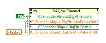
I don't know why the noise could be the cause of your encoder can increase more slowly... However I have a suggestion on the map of the M series (6259):
M-series cards have a digital filter integrated on the lines of the PFI (see the user manual of M series). Looks like the noise is a series of 3 ~ US of impulses (1/10 to 1/30 kHz). Of the available filtering frequencies that you can set on your M series is 6,425 US, which must ignore the impulses (high or low) that are less than 6,425 US. You can configure the digital filtering with a property node DAQmx:
One caveat is that the driver only allows you to configure the digital filtering for entries counter on M Series devices. For example, you can use a digital filtering directly on your task of encoder, but not for your sample clock HAVE. A workaround can be found here, which is to set up a dummy counter job to define the PFI filter for your task to HAVE. If you use the same PFI line for your encoder and the task to HAVE it, you should be able to just set up the PFI filter through the task of the encoder and worry for the workaround.
Regarding the RIO Flex, I think that you could implement something similar on the FPGA, but I'm probably not the best person to comment on this subject. It would be probably a lot more work to use the DAQmx API's built-in filtering.
Best regards
-
1042 q with PXI 8360-controller and maps of Pickering
Hello
I have a 1042 q with a PXI-8360 controller chassis and some maps of Pickering.
Connected to the XP - PC with a PCI-e-card-
Installed is only neither Max nor-PXI, Ni-Visa...
Now the question is how to set up the chassis in the 4.7 or max?
In Max, I see a line with PXI system (unidentified) under "Geräte und interfaces". I tried to load some of the deliverered ini with pxi OR cd files, but I can't control anything.
Can someone me a gibe hint what to do?
I have doenloaded a pickering Web site pipx40vpp.zp file which should cover all my map of pickering a has also a few frontpanles.
But at the start of the frontpanels it says "no card detected". I think I must first of all put in correct place in the max.
Thanks for any help
Thank you very much for the help.
Problem is now solved:
The main problem was that the PCIx1 slot is not working. I put the card in an another PCIx slot and then he worked at the same time.
I found this trick here:
http://digital.NI.com/public.nsf/allkb/05B7131814A5DDA38625710F006BB098?OpenDocument
Try different PCI or PCI Express locations in the host PC for you MXI interface.
The algorithm that use certain BIOS has best behavior in certain time slots than others.Maybe someone will need it in the future.
-
Problems with a major acquisition using ConfigureDataPositionDelay time
I do not think that my cards are accept the entrance of the 'ConfigureDataPositionDelay' function as expected when I created a loop of "sweep" delayed. (I'm trying to find the optimal placement of strobe).
I have a PXI system with PXI-6552 3 cards. (only the first two cards capture data HAD)
My waveform is running at 40 MHz.
I'm not use HWC because I want the option to let the drivers on (conduct 0V) so I can use their impedance of 50 ohms as line terminations.
I use HSDIO driver version v1.6. There are problems of compatibility with some legacy code NIDAQ-Tradition and NI488.2 in my test environment that yields 'Visual C++ Run Time error (R6030 - uninitialized CRT)' if I try to use v1.7
Here is an excerpt of the pseudo code for my scan:
Loop strobe_placement from 0.0 to 0.9 in 0.1 steps:

  niHSDIO_ConfigureDataPositionDelay(card1acq, pin_list, strobe_placement)
  niHSDIO_ConfigureDataPositionDelay(card2acq, pin_list, strobe_placement)
  niHSDIO_Initiate(card1acq)
  niHSDIO_Initiate(card2acq)
  niTClk_Initiate(3, gen_array)

  niHSDIO_WaitUntilDone(card1acq, 2000)

  niHSDIO_FetchMultiRecordU32(card1acq, data_rec_len, 1000, 1, 1, samp_data, wfm_info)
  niHSDIO_FetchMultiRecordU32(card2acq, data_rec_len, 1000, 1, 1, samp_data, wfm_info)
Now, I know that the 'ConfigureDataPositionDelay' function works very well in my initialization code of the system when my application loads first upward. This initialization code defines MANY features on all my cards and uses MANY different driver calls. Maybe I need to call another function of driver AFTER the call of 'ConfigureDataPositionDelay' to force the material to make the change?
Oops. It's always the simple things.
I had ConfigureDataPosition the value NIHSDIO_VAL_SAMPLE_CLOCK_RISING_EDGE during my scan
instead of NIHSDIO_VAL_DELAY_FROM_SAMPLE_CLOCK_RISING_EDGE as it should be.
Now my scanning works very well.
-
problems with, phone, 6, Bluetooth kit, Nissan, after update, for, Rios, 1.0.2
After the update to ios 10.0.2 - trying to use bluetooth to call my vehicle, it says: "this article is not in your phone book." How can I solve this problem?
Greetings, joybelino1!
Thank you for joining the communities Support from Apple! I can't wait to see that you are having problems with your Bluetooth in your car! The good news is that Apple has a great article that will help you with measures to try to resolve the problem. Read this article to gethelp to connect your iPhone, iPad, or iPod touch with your car radio. Even though he talks about problems with the connection, it also has the steps for other questions you may have once connected.
If you use Bluetooth
- Consult the user manual of your car stereo to get the procedure to a Bluetooth device.
- On your iOS device, drag up to open Control Center, then press on
 twice to turn on Bluetooth and turn it back on.
 - Restart your iOS device.
- On your iOS device, Cancel the twinning of your car radio. On the screen of your car désapparier your iOS device and any other device. Restart your car and your iOS device, then pair and connect again.
- Update your iOS device.
- Install the updates to the firmware of your car radio.
- If you still not connect, contact Apple technical support.
Have a great day!
-
Anyone having problems with WiFi connectivity after upgrade to Sierra?
I was wondering if anyone else knows issues with WiFi connectivity since the upgrade to Sierra 10.12? I have not had any problems with connectivity WiFi previously on El Capitan. Now I have regular randomly loose connectivity. My internet is cable and when it is connected I have a 100% connection. My details of iMac and I have used only 10% of my storage.

No problem with my iphone 6.
Hello AspDesigns,
I understand that, since the upgrade to Mac OS Sierra, your Mac seems to have trouble staying connected to Wi - Fi. Fortunately the diagnosis built-in wireless can help identify the source of so much trouble.
Search for Wi - Fi using your Mac problems
See you soon!
-
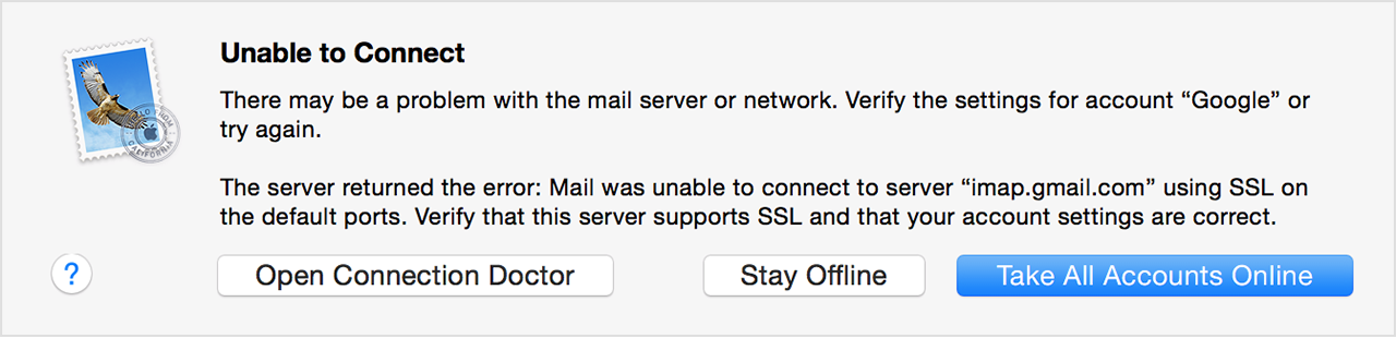
Problems with mail after switching to macOS Sierra
Hey all
After having recently upgraded to macOS Sierra, I am unable to read my mail.
I get the following error every time I check on "Get Mail".
There may be a problem with the mail server or the network. Check the account settings "*" or try again.
The server returned the error: Mail could not connect to the server 'pop1.tribcsp.com' using SSL on the default ports. Verify that this server supports SSL and that your account settings are correct.
What does this error message mean and how can I solve this problem.
Thank you
Hi Michael,
I see your message that you get an error in the mail indicating that there is a problem with the mail server or the network. To help get this problem resolved, I suggest that you follow the steps below:
If mail refers to a problem with the mail server, or the network
Mail will say that it is impossible to connect due to a problem with the mail server or the network. For example, the message may refer to a connection that has expired, or too many simultaneous connections:
If you are connected to the Internet, but the connection has expired, your email provider might be affected by a discontinuance of service. Contact them or see their status Web page to ensure that their e-mail service is online. Examples of status pages:
- iCloud mail status
- Gmail status
- Status of Yahoo mail
- Status of the AOL mail
- Status of Outlook e-mail
If the message indicates the number of simultaneous connections, too many of your devices is check your e-mail account at the same time. Quit Mail on one or more of your other devices.
If you are still unable to send or receive e-mails
- Make sure that you have installed latest version of the Mac software updates, especially if the problem occurred immediately after the installation of a previous update.
- In OS X El Capitan or later version, you can see a status icon and the short error message in the upper right of the Mail window, under the search box. The message may indicate 'Network offline' or 'Connection failed', for example. Click the message to see more details on the issue.

- Check your connection to the Mail connection doctor. It might be able to say more on the issue.
If you cannot send or receive e-mail on your Mac.
Take care.
-
iMac 27 "mid-2011 - Intermittent problem with CPU fan running at full speed and sleep mode.
Hello!
My iMac 27 "has an intermittent problem with the CPU fan runs at full speed. Sometimes it happens at the time when I start it, sometimes only in my session, and sometimes only after a certain time. So does seem to be a problem of "heating".
Second issue is with the mode 'sleep'. It may occur also at any time, at the start of the iMac, session, or after a certain time. But once he starts to go in mode 'sleep', when I wake up, it goes right back in mode after a few seconds and that it will continue indefinitely until I restart the computer.
What could be?
Please help me!
4ntoine
Here is my model of iMac:
iMac 27 "mid-2011 model 12.2
Intel Core i7 3.4 GHz
AMD Radeon HD 6970M 1024 MB
OS X El Capitan 10.11.6
SMC 1.72f2Boot ROM IM121.0047.B23
reset the SMC
Reset the management system (SCM) controller on your Mac - Apple Support
-
problem with playing the clash of clans
I'm having some problems while playing the clash of clans on my 2 mini ipad screen does not seem to meet sometimes as if it was some sort of delay so I have to tap several times in order to use a filter or throw the troops on the battlefield.
Hi Trinitygr,
Thanks for posting in the Community Support from Apple! I understand that you are having problems with your iPad screen while playing a game. I like to play games on my iPad and I don't see how this could be a nuisance. I'm happy to offer assistance.
Are you only had this problem when using the app clash of Clans, or does it happen in all applications? I recommend to start by following the steps described in this article:
If an application you have installed unexpectedly closes, unresponsive, or does not openTake care!

Maybe you are looking for
-
Deliver the mail client. Can't see the e-mail responses.
original title: mail Why my e-mail address would show that I have 1 and when I answer it and then they send it as a response it shows 2 but it does not show their response just the original?
-
Aspire V3 - 772G | Dolby Home Theater
I swapped the hard drive for an SSD and installed 64-bit Windows 8.1 from scratch. Tried the latest audio driver from Realtek (6.0.1.7246 R2.75), but which did not include Dolby Home Theater. Uninstalled... Tried the latest audio driver Acer (6.0.1.7
-
I find the e-mail in windows live and use xp
-
HP DV6 3210US CAPS LOCK FLASHING & WIFI AMBER CLEAR
I have 32310us dv6 that will not start. It starts at a flashing caps lock button and onrange and soild key wifi in light of strong Pentecostal power button. No other lights on the area of the main panel. No beeps are heard spin cd just in a first ti
-
Upgrade Windows 10 doesn't do much
After you download the update of windows 10 the wizard of windows 10 upgrade, it takes quite a long time to install it. After installation, it tells me that it is restart my computer to complete the installation. It restarts, goes to the 'installing