Pulse 500hhz signal
I use the USB-6251 daq card. I need to measure the number of pulses is entered a few start and end time with the saignal may vary up to 500 k hz. Also I need the arrival time of pulse for every pulse.
If I configure the task for pulse width tab in daqmx I'll be able to measure the time of arrival count pulse and pulse (up to 500khz)
I guess what you are the reference to is the time stamp. When you use the low level of VI of DAQmx you can get signals as data type of waveform, which has the moment t0 and initial sample, although dt values sample sampling intervals Y. You can do the rest by getting each of the parameters in the range of the waveform.
I hope this helps!
Tags: NI Software
Similar Questions
-
Generation of pulse type signals cannot be done. Help. Please, I beg you.
How can I generate a computer signal in labview software but using is no DAQ?
I need a continuous impulse which is essentially increasing and decreasing slowly WRT time. i.e. it is a pulse, it is already given in labview simulate signal option. I need the DC signal which can be will be the merger of more than 2-3 signals. Please help me with the solution, if possible, or any solution as soon as possible.The image of the pulse is attached.
The link of the pulse is: file:///C:/Users/Priyabrata%20Saha/Desktop/internship/pulse.JPG
Have you tried "simulate arbitrary signals"?
-
Continuously perform calculations on the data
Hey guys,.
So I have this program that generates pulses of signals using NOR-SCOPE, and I initially did so that each time that the user presses a button that they will perform certain calculations in order to generate a value that is stored in a table. My mentor now wants me to do so that it generates continuously pulse signals (not a single signal) and adds the values in a table. The signal seems so I need to use the parameter N samples on NI SCOPE as it does in the code below, although if anyone has a way to change this, it would be nice too.
So basically, how can I calculate continuous pulse generated automatically over time signals? The user does not have to run the program and the computer does the rest.
Thank you!
You must migrate to a structure of producer/consumer. In the loop of the producer acquire the data contimuously and pass it to the loop of consumption. In the loop of the consumer, analyze the data and store the data as needed.
A variation on the theme that I recommend is that instead of using a queue to pass data, use a user-defined event. The reason for this change is that your current code (which is basically what will end up in the loop of the consumer) is so pass data to loop through an event will allow him to fit into the current structure of the user interface.
Oh, Yes, one more thing: get rid of the Express live. It's time to remove the training wheels...
Mike...
-
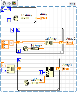
How to insert a 1 d table row in a 2D array?
I have a vi that acquire several pulse encoder signals and store it in a 1 d table, and I want to move the data to a 2d array and fill it. I mean I want to acquire the signal and keep in line 1 of table 2d and keep in line 2 of the 2d table build again and keep it successively.
How can I do?
Many ways... same result. The first and the last are more effective.
-
signal level for pulse width measurement
Hello
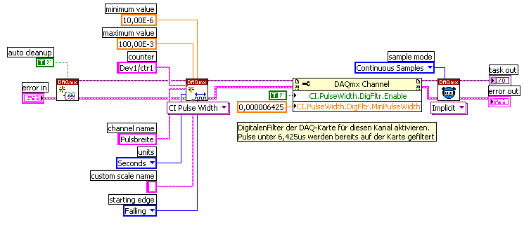
I am able the pulse width with the meter M6251 (CI pulse width)
I understand that the digital input works on the TTL levels (0, low 8V 2, 4V high).
Can you say exactly in which the level of signal pulse width is measured?
Thank you
Ralf
In fact, the transition from low to high (or vice versa) is located in between 0.8V and 2.2V. It is not specced exactly where it will be (although you'd be able to get a better idea, if you have an analog source, you can slowly increase until you see line status change).
This is why the fast rise time are important to accurately measure the digital signals.
Best regards
-
How to set the output meter channel to generate a signal pulse using DAQ6008
Hello there I am generating a pulse signal of 100 Hz and a duty of 20% of the 6008 data acquisition cycle using visual studio 2013. I have code that needs to generate this but I'm not sure on how to set the channel output meter. When I run this NI MMAX and my vb error code indicates that the physical channel is not supported. I am a user of data acquisition were first and would appreciate any help offered.
If you look at the USB-6008/6009 User Guide and specifications, you will see that the counter in these devices cannot rely as edges of entry. It cannot generate a pulse.
Lynn
-
filter the peaks on the signal from ECG pulse!, help!
Hello
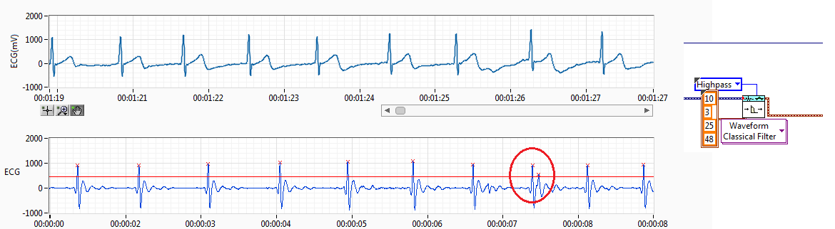
I have RCV of the ECG signal. I filtered the ECG signal and get the resource (interval between each pulse of ECG) records.
The source of the signal have noise I use a threshold but sometimes spikes of failure. Like the previous capture. Normally, if you get a pic of fault detected, I'll try to find this index to add to the left or right of the peak, normally I add to the lower value. This works if it has only a bad impulse between 2 good.
The problem come when I have more than a ridge between the two coupons.
Also, when the impulse of R a loss threshold I have trying to find the index and get 2 new reading making division 2 peak value.
I have attached the method I've used to adapt it. I only works if I have 1 Ridge added on real measures of R or pulse 1 loss R, when I have several pics no work.
I would like to hear an idea to make it work better. I don't like the idea of removing the value interval, I have 2 hours of reading and if I remove the values I have lower data outoput is why I tried to summarize or division of values to get the correct reading without losing any data.
Perhaps, there is any better filter for ECG of entry, so I have a R-own pulse and less noise between ECG pulses.
Any advice is welcome.
Best regards, Fred.
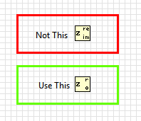
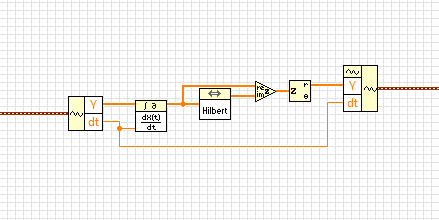
Almost. in the last step, you have extracted the real part of the complex waveform. Instead, you must retrieve the extent.
BTW, this idea isn't mine. I got from this article
http://www.ScienceDirect.com/science/article/PII/S0010482501000099
-
VI to convert input signals NI 9402 in a RPM value, based on the frequency of the pulses
Hello
I'm looking for a VI convert an input signal NI 9402 in a RPM value, based on the frequency of the pulses. Is there such a thing that exists in the library of national instruments?
I run LAbview 2014 integrated control and monitoring on on a cRIO 9802 high performance integrated system with NEITHER 9402, 4 channels, 50 LV, LV TTL Module input/output digital, ultra high speed digital i/o for the cRIO module.
Any help would be greatly appreciated.
The easiest way is to use the FPGA to get the time between the edges of your pulse increase (shift registers to maintain the current situation and the time will be necessary). This will give you the period. If it's a single pulse per turn, then the number of laps is just 60/T, where T is the time in seconds.
-
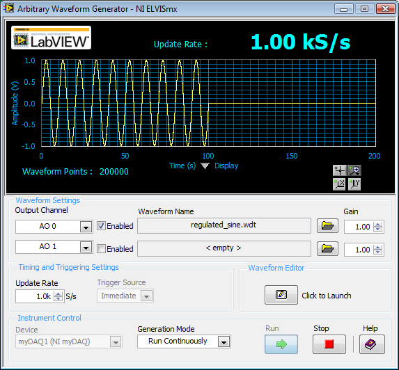
How to generate a pulse with the signal generator?
Hello
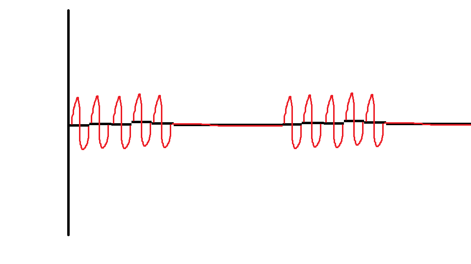
I would like to ask if anyone knows how to use the Elvis platform to generate a regulated pulse wave?
It should look roughly like the picture above. A sine wave with the regulation.
Anyone who can answer my question please respond to my post.
Thank you.
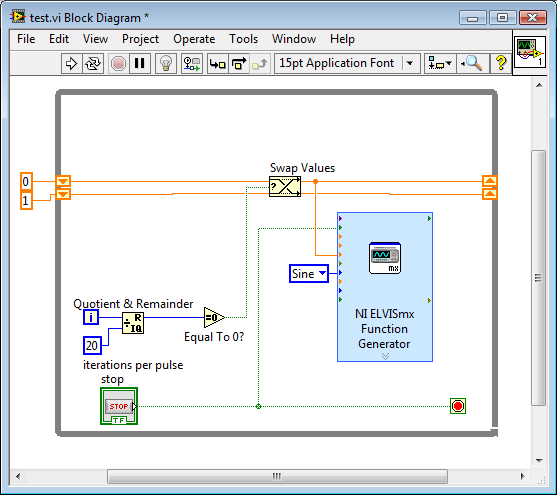
You are using LabVIEW to generate the waveform or using the Soft front panels? In LabVIEW, you can use the express VI generator function and specify the Type as "Sine". Then, simply change the amplitude of the sine wave. During the actual pulse, the amplitude would be what you want (i.e. 1 V) and while the pulse is idle, set the amplitude to 0.
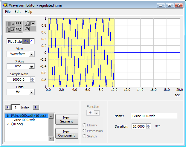
If you use the soft front panels, you can use the Waveform Editor to create a waveform that includes a sine wave for the length of your pulse and then the values of '0' for the rest of the time. Then use this waveform in the flexible front of the arbitrary signal generator. Simply create a component of sine as the first part of the wave and then add another element to a level DC '0' for the rest.
-
Create two independent signals and a pulse train with NI USB-6259
Hi all
I'm new to the forum, I searched but I've found no info about it.
I have recently set up a vi that is able to generate from an NI USB-6259 case two different signals in frequency, amplitude and phase (see attachment).
To do this with each cycle of the memory buffer size is changed accordingly for frequencies in order to see a whole number of periods and, thus, having not leak in the generation (or breaks).
Now, I would like to generate a pulse train at a frequency that is an integer multiple of the frequency of the input signal (not the 50 Hz one).
The resulting frequency of the pulse train could be changed on the fly (or at least be updated at each new round of vi).
I'm stuck because I have already said that two analog output channels and I want the pulse train so that a digital camera for my Board (channel PFI) output, you have any ideas?
Thank you very much
Alberto
PS. the vi is "program generazione.vi" but you must first install "signal.vi production".
Hello
It is a simple .vi which generates a configurable, buffered pulse train dynamically. I also want to let you know that with this type of advice (DAQ), it is impossible to update the output in real time. You must be careful because the time between you use "DAQmx Write" and the output effective physical change not IS NOT FIXED.Kind regards
Matteo
-
pulse width of measurement of signals generated by data acquisition
Finally, I would like to:
Start a counter pulse width measurement and the analog output at the same instant.
Stop the measurement with an external digital signal pulse width.My current plan is to use a digital output on the acquisition of data to synchronize a digital input and the start-up of the meter input. The digital input will be a trigger to start for the analog output. This works, except for the meter.
While trying to implement this, I tried a simple test to generate a digital pulse with the acquisition of data and wiring for counter inputs. It does not, even if it seems perfect to an oscilloscope. Then, without changing the software at all, I connect a function generator to my counter entries, and it measures pulse flawless widths.
I'm actually implemented it with a Python wrapper around the C DAQmx API, but I recreated in LabVIEW, and it has the same. VI attached. I have the latest drivers DAQmx.
Accidentally, I posted this in a forum for LabVIEW, as I managed to post with the account of a colleague. I think 2 ups live as this mandate to another post. I'm sorry. Former post is http://forums.ni.com/ni/board/message?board.id=170&message.id=389856.
Solution: I had to set the channel to counter with implicit synchronization. In addition, the sampsPerChanToAcquire must be at least 2, if not, there is an error. I still don't understand why it worked with a source of external impulse, however.
DAQmxCfgImplicitTiming (task_handle, DAQmx_Val_FiniteSamps, 2)
-
Frequency of signal and pulse duration varying as to reduce the duty cycle
To sum up my problem, I am creating a period and the controlled voltage pulse sequence, but as I decrease my cyclical report, the distance between each pulse begins to become irregular. More precisely:
I want to have three pulses, each a positive amplitude specified, long, with 23 ms between each 80 microseconds. After these three impulses, I would have a negative pulse of 3 * than amplitude, followed again by Ms. 23 this cycle must be repeated 260 times.
I tried first of all to create the positive impulses to help simulate Signal VI, assigning a square wave with a frequency of 43.327556, an offset of 0.5 and the amplitude of 0.5. And the operating cycle as the default value of 50%, the signal seems to be normal (constant frequency and the duration of each pulse is equal;) "I'm in a position with an oscilloscope). However, when you set the duty cycle for. 3466%, the time between each pulse varies and some legumes are longer than others. I wrote the data able to file directly from fake Signal VI to ensure that he was not only a problem of scope, but it seemed that writing to a file of measure has not sample enough points for me to accurately measure. Even decrease the market barely 10% factor, I see the question arise already.
So my question is, I'm doing something wrong here? It is a kind offset of Labview to try to perform a duty cycle that small? And are there any alternatives to the way I have this set up? I thought I would try to use a train of pulses instead, but I'm not very familiar with this and I know, you can't control the amplitude of the pulses.
Any help is appreciated! Thank you very much.
My guess is that you are limited by the sample rate. If the difference between the two signals time is less than the sampling period (1 frequency / sampling), you will not be able to generate the signals you want.
Please tell us the sampling rate, you use and the settings that work and those that do not. If your data file is not too big, please post so that we can see some data. Post your VI can help too. Check the default settings before you save the VI.
Lynn
-
How can I use my PXI-6115 meter analog signal trigger to generate pulses of frequency
I work on a PXI-6115 DAQ card and want to using the analog signal to trigger the counter it's generating frequency pulses. The manual says the analog trigger is supported, but I can't use an analog signal to trigger the start of work, in the test, I use the counter 0 to generate pulses and use the signal input port analog trigger PFI 0, can someone tell me what it is? My test VI. & error message appears in the attachment.
Best regards
If you read the error you can see digital triggers are the available trigger only when you use the output of the counter.
You can work around this by setting up a dummy analog input task which will trigger an internal digital triggering when he sees the right analog trigger.
See this thread for more details:
-
Count the number of 1 is present in digital waveforms obtained by converting the pulse signals.
Hello
I use Analogtodigital.Vi to convert the pulse of the sequences in digital.signals.I am able to get the representation of digital waveforms of impulses.
But how to count the number of 1 is present in the converted digital waveform. I want to count the number of 1 is present in the digital waveform converted.
Thanks in advance.
Have you tried the block scheme of similar to the Digital.vi of opening?
It creates an array 2D uncompressed 1 and 0, which is the binary 16 bits A/D conversion of each element in the array Y of the input waveform. You can use the DWDT digital Array.vi Boolean to convert a 2D Boolean table. Then convert Boolean values to 1.0 and summarize the array of integers. The sum must be the number of 1 bits in the digital waveforms.
Lynn
Note: The VI attached is saved in version 8.6. When I have it saved for the previous Version a warning was generated about the possible differences in the versions. Let me know if it doesn't work, and you are using which version of LV.
-
Generate the pulse signal signle on the digital output line
Hello
I am now writing a program using c# and DAQmx.
I have a NI PCI-6514card and I want to send a signal for half a second to a single line of output.
I know how to write online by using the DigitalSingleChannelWriter object, but I want this signal, disappear after a period of time.
Thanks in advance for your support.
J.. Gasser
One thing is certain:
C:\Users\Public\Documents\National Instruments\NI-DAQ\Examples\DotNET2.0\Counter\Generate Pulse\GenDigPulse\cs
It is on Vista.
On XP, I believe that the path is:
C:\Documents and Settings\All Users\National Instruments\...
Maybe you are looking for
-
ICloud question: transferred photos off my iphone to icloud. You want to remove all of the iphone, but ensuring that they will remain on same icloud if deleted out of my phone. Thank you
-
I have a HP5610 perfect condition except after having installed Windows 10. Now I can't scan. Any help?
-
Vista Basic As stated above I get this error message and can not do in SafeMode to rstore system dates back to an earlier era. I did the system of tapping F8 and tried all offered options of safe mode, but it does not open in any safe mode, just this
-
OfficeJet Pro 6830: Can't print multiple copies with my new 6830 Pro of Officejet
I installed my 6830 and have updated the drivers. It is on my home wifi network and works well. All functions work perfectly, but when I try to print multiple copies by selecting the number of copies in the print dialog in Adobe Reader, MS Word an
-
Unable to import video clips format .mts for Windows Movie Maker
Importing files Movie Maker I downloaded some video footage to my office at the top of a camera. I tried to import it into Movie Maker off the file to my desktop but without success. The files are of MTS