pulse width of measurement of signals generated by data acquisition
Finally, I would like to:
Start a counter pulse width measurement and the analog output at the same instant.
Stop the measurement with an external digital signal pulse width.
My current plan is to use a digital output on the acquisition of data to synchronize a digital input and the start-up of the meter input. The digital input will be a trigger to start for the analog output. This works, except for the meter.
While trying to implement this, I tried a simple test to generate a digital pulse with the acquisition of data and wiring for counter inputs. It does not, even if it seems perfect to an oscilloscope. Then, without changing the software at all, I connect a function generator to my counter entries, and it measures pulse flawless widths.
I'm actually implemented it with a Python wrapper around the C DAQmx API, but I recreated in LabVIEW, and it has the same. VI attached. I have the latest drivers DAQmx.
Accidentally, I posted this in a forum for LabVIEW, as I managed to post with the account of a colleague. I think 2 ups live as this mandate to another post. I'm sorry. Former post is http://forums.ni.com/ni/board/message?board.id=170&message.id=389856.
Solution: I had to set the channel to counter with implicit synchronization. In addition, the sampsPerChanToAcquire must be at least 2, if not, there is an error. I still don't understand why it worked with a source of external impulse, however.
DAQmxCfgImplicitTiming (task_handle, DAQmx_Val_FiniteSamps, 2)
Tags: NI Hardware
Similar Questions
-
Run two Executive files get signals of a data acquisition
I am a new user of LabView and I try to execute the two files on a computer that gets signals of an acquisition of data (that is, NI USB-6210). However, a single file is working correctly and display the values of signal while the other stops. I couldn't run two of them simultaneously. How can I solve this problem? Please do me advised.
You can not. You can not have two different tasks running on the same device at the same time. The second executable probably shows an error of-50103, assuming you have something in there to display errors.
-
signal level for pulse width measurement
Hello
I am able the pulse width with the meter M6251 (CI pulse width)
I understand that the digital input works on the TTL levels (0, low 8V 2, 4V high).
Can you say exactly in which the level of signal pulse width is measured?
Thank you
Ralf
In fact, the transition from low to high (or vice versa) is located in between 0.8V and 2.2V. It is not specced exactly where it will be (although you'd be able to get a better idea, if you have an analog source, you can slowly increase until you see line status change).
This is why the fast rise time are important to accurately measure the digital signals.
Best regards
-
sampling frequency of DAQ assistant for pulse width measurment
Hi all. I want to measure the pulse width of a digital signal of about 1 kHz, via digital DAQ vi assistand pulse width. I need to measure the pulse width approximately 100 Hz.
I put 1 sample on request and in one of the other method of as implicit synchronization for continuous measures that I met at the error. He doesn't let me frustrating that I could not measure a measurand jut at 100 hz.
I use Daqmx and windows 7 sp1 and labview 2012.
Thank you
OK I have the solution, it's better to see the example and do not use daq assistand and use the primary functions.
Counter-read Pulseand width and frequency .vi (continuous)
-
Generate PWM signals with 1.5 ms pulse width
Hi all
I'm working on a project where I need to generate a PWM with a pulse between 1.3 and 1.7 width ms to order a servo rotation continues. LabView is in communication with an arduino Uno microcontroller by LINX. My original plan was to use the milliseconds of wait function in LabVIew to do this. I put the PIN PWM high, wait 1.3 or 1.4 ms then set the low axis for 20 less ms pulsewidth. before repeating. This is how I have gnereate one using the Arduino IDE pulse width, so I thought I'd be able to do something similar here. However, as I'm sure is already obvious to anyone who reads this, the milliseconds waiting finction in LabView only accepts the whole entries. Arduino IDE is similar, but there is a delayMicrosecond function that can be used, so if I want 1.4 ms I use 1400 US snf then convert it in ms for the 20 least part. How can I do something similar in LabView? Also. When I run the program as what with a 1 ms pulsewidth I have a strange behavior. It in fact generates a PWM signal, somewhere between 0.75 and 1.25 ms and with a period between 50 and 54 ms, it turns into a model each about half a second. I'm using LabView 2014. Any ideas?
Chris
You can't get that kind of resolution with Windows and any delay you specify will have considerable jitter due to Windows. If you can pass values with Linx and allows the arduino to control them, stick with that.
-
-Measurement of the pulse width specifies the timeout?
I'm trying to set up a simple project of Signal Express that measure the pulse of two separate signal lines width.
My PCI6224 has two entrances of meter and then run each pulse in the entrance of a meter line, respectively.
The I set up the express project signal attached, which consists of two simultaneously runnings tasks DAQmxAcquire. Each of them is set to measure the pulse for one of the pulse width. I then connect the results for further analysis.
This configuration works very well from time to time. The problem arises when the impulses do not arrive quickly enough and the acquisition of the timeout action. Looks like that has a simple solution - just increase the time-out - but I can't find a single setting around the affects, the time-out! The time-out period is always 10 seconds, regardless of what I do.
Can anyone help?
Thank you.
Hello rothloup,
Unfortunately, there is no option to change the time-out Signal Express for a task entry counter. This has been brought to the attention of our developers.
Reading a DAQmx LabVIEW VI has a time-out node you can specify the time-out period, even in the tasks of meter. I suggest you try to implement your system in LabVIEW (if you can).
Here is a tutorial on how to make PWM in LabVIEW.
http://www.NI.com/Tutorial/2991/en/
See you soon,.
-
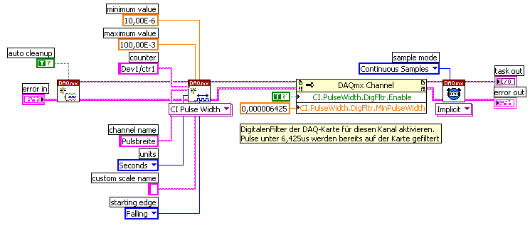
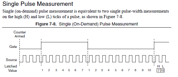
single pulse width measurement
Hello
I'm trying to measure the duration of a single pulse using ctr0 on an SMU-6361.
The signal in the attachment Capture7.jpg, goes PFI 9, ctr0 door.
The problem is that the counter see ' s the front up and stops. The pulse width is not given as can be seen in the output (Capture8.jpg).
I get the same results by using Meas_Pulse_Width.vi example.
Is something wrong with my SMU-6361?
Oh, I think I know what it is.
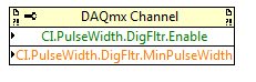
Change the task "pulse width" (a single pulse of height) instead of "Pulse" (the high and low time of a pulse repetition measures). Change the DAQmx Read to use Ctr > single sample > DBL (instead of pulse). Change the property filter node digital to use the corresponding properties of the "pulse width" (the filter is still necessary):
The task of the pulse was not period initially because you receive a series of noise pulse repetition (and so it was a very low period). With the filter, this time since the noise disappears now and the single pulse did not finish measuring the pulse (which requires a high and some time):
For the record, I agree that it is confusing that there is the "pulse" and "Pulse" measure and they do different things.
Best regards
-
NI 9401 pulse width measurement.
Hello
I'm not sure that I understand very well the pinout diagram. At the present time, I have a NI9401 in a NI 9172 chassis.
DIO0 and DIO1 are connected at the gates of light. I have an opto switch and I want to measure the pulse width when an object blocks passes through the slot. Can I use one of the other free entry of the for do?
The entries are DIO2, DIO4 and DIO5.
The other IO pins are used as triggers.
See you soon
K
Hi Kamilan,
If you explore in the measurement and Automation (MAX) and find your 9401, you can right click on the device and select "Pin of the device" which pulls up a window that says what features each pin on the device. For example, according to this document, DIO2 is PFI2 to THE CTR0 CTR0 B and FREQ OUT.
To answer your second question, do a right click on your device and create a new task for your 9401. "You should do an acquisition of signals" counter input "pulse width and select CTR 1 on your device. Once you do this, you can configure the parameters of your task and Max it will tell you where you need connect your signal source, which, for me, is DIO5.
I would like to know how it works for you, thank you!
-
with pulse width measurement external sample clock
Hi all
I use a NI 6220 (programming with ANSI C) Board and I would like to make a "unique pulse width measurement' by using a signal from the outer door and an external signal source.
The program and the card with the help of the "DAQmxCreateCIPulseWidthChan" command works only partially as expected. Namely, the outer door has worked, but the map uses the internal time of 80 MHz base signal instead of the external source connected to the source by default PIN (PFI, 8).
I tried send an another PIN PFI on the default source pin using the command 'DAQmxConnectTerms', but this did not help either.
Obviously, I'm missing something...
Best, Uli
Hi Uli,
I posted in your thread here.
Best regards
-
NI6602 pulse width measurement: do I have to use an external sample clock?
Hello
In the example .NET 4 "MeasPulseWidthBuf_SmplClk_Cont", it is said in the comments that:
An external sample clock should be used.
Hi mola.
This specific example measures of sample-clocked pulse width. This type of measure is supported only on new hardware such as the X series cards and will not run on the 6602.
Your application that you have linked uses Implicit timing, which means that the signal is using the sample clock. In other words, at the end of each pulse duration which can be measured, the sample is deterministic locked in. So you end up with a table in the buffer of each pulse width which is seen by the meter.
Best regards
-
How can I use two counters simultaneously to pulse width measurment
Hello, everyone!
I'm new to Labview. I currently have some cDAQ9171 and width measurment with 9401 impulses. My understanding is that the 9401 was 4 meters, which means that I can use these meter separately. However I have the following problem.
1. I use ctr 0 and ctr 1 (PFI 1 and PFI5) to measure two different impulses. However, it seems that there is an interference between two counters. How can I make two counters working simultaneously and separately?
2. I first try a pulse width measurment counter in Labview signalExpress. My pulse width is about 0.4ms. However, I can't get the right result, if I choose the starting edge is on the rise (the results always around 20ns. Only if I revise my pulse and pick the starting edge is down, I can get reliable results.
I'm confused about these issues for about 3 weeks... Is there someone can help what can I do with that?
I have attached a simple vi...
Thank you very much!
-
How to generate a pulse with the signal generator?
Hello
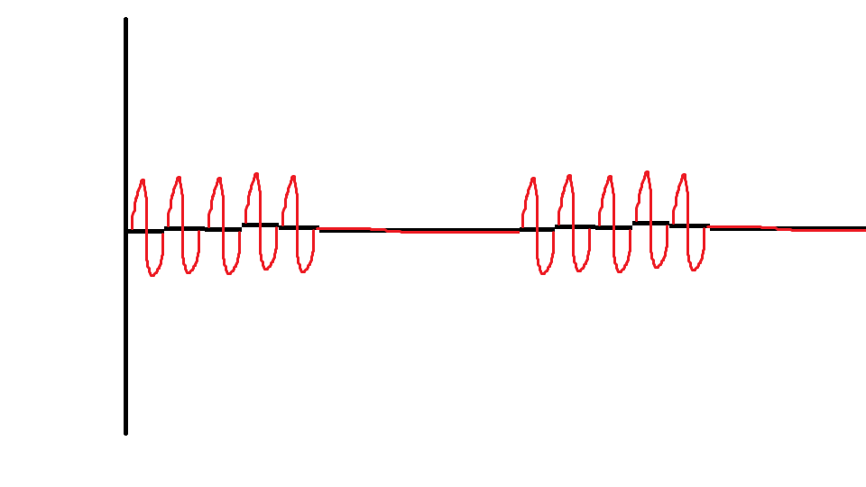
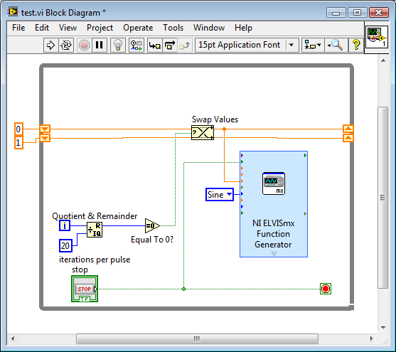
I would like to ask if anyone knows how to use the Elvis platform to generate a regulated pulse wave?
It should look roughly like the picture above. A sine wave with the regulation.
Anyone who can answer my question please respond to my post.
Thank you.
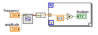
You are using LabVIEW to generate the waveform or using the Soft front panels? In LabVIEW, you can use the express VI generator function and specify the Type as "Sine". Then, simply change the amplitude of the sine wave. During the actual pulse, the amplitude would be what you want (i.e. 1 V) and while the pulse is idle, set the amplitude to 0.
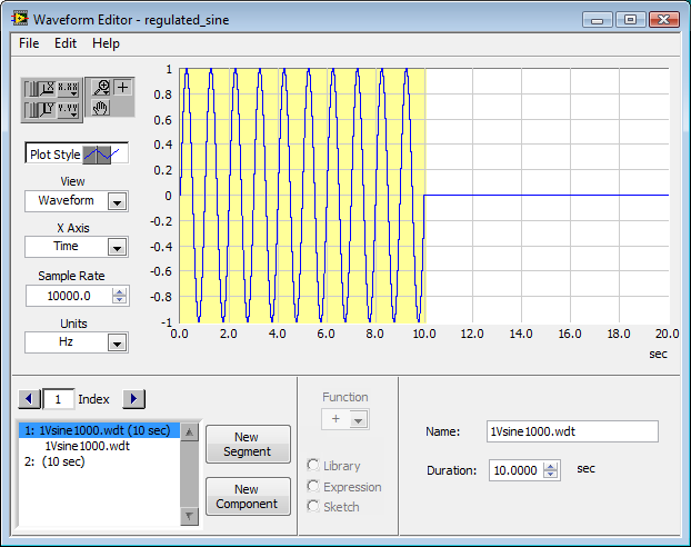
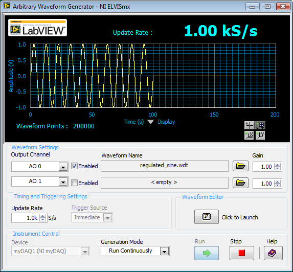
If you use the soft front panels, you can use the Waveform Editor to create a waveform that includes a sine wave for the length of your pulse and then the values of '0' for the rest of the time. Then use this waveform in the flexible front of the arbitrary signal generator. Simply create a component of sine as the first part of the wave and then add another element to a level DC '0' for the rest.
-
With the help of modulated signal pulse width (square wave) to control when a signal is enabled or disable
Hello all
I am using a modulated signal to labview created pulse width (square wave) to control when a signal is activated or not.
Here is my logic and a concrete example:
(1) the wave source signal is continuous
(2) use a PWM (square wave) created in labview to control when the signal is enabled or disabled
(3) if the PWM (amplitude) signal is superior to 0 play signal PWM is not greater than 0 do not play signal.I use actually this to the sequence step / pulse several distinct magnetic coils using my audio card (which has several channels of audio output), I have a signal in labview played constantly. As to compare it to the PWM (square wave) which controls whether or not the signal is played on each separate channel. That way I can control which coil is on and offshore and in what order they are activated.
I couldn't find an edge detection for a square wave created in labview, so I tried the limits, but it doesn't seem to work unless I change the phase manually and it only goes 1-1. I'm just trying to compare the PWM (edges of the square wave) already created by labview / play a signal if the pulse is greater than 0 and it shuts off the signal, if she is less than 0.
Should I do this another way
TIA
A waveform contains an array of values. You must check every value and respond accordingly:
-
PXI-4072 can measure a pulse width?
Can I use a pxi-4072 DMM to measure a pulse width? With the help of labview8.6.1 can I get period information and freq but I am interested in duty cycle. Thank you, Kenneth
Hi Kenoss,
If you use the PXI-4072 to acquire waveform data, then you can try to use the Measurements.vi impulse to get the duty cycle.
Best regards
Tony_G
-
Output a TTL HIGH 10 usec via the PFI port on AWG signal generator
LV dear community,
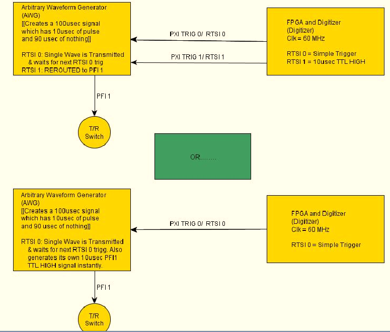
I want my signal generator (PXI-5422) to produce a pulse of 10usec with its PFI1 range each time that a wave of exit CH0. The frequency of repetition of the CH0 impulses and the port of PFI1 is 10 kHz. Is it possible for the signal generator automatically generate this HIGH TTL signals for usec 10 on the PFI1 line all at the same time produce a long-wave 100 usec?
Another approach, that I'm considering is to re - route a pulse of RTSI1 (10usec) from an FPGA and output via port PFF1 of the GTS. However, I doubt that this is possible, as the HELP MENU for the working group said that the report can only occur when the Working Group is in "idle" mode.
Any help will be greatly appreciated!
Have a nice day
 I have attached a diagram of operation that hopefully, explains what I'm trying to do a little better. Once again thanks for looking!
-Daniel
Hi Denn_Mann,
To get around the limit of 320ns, you should be able to use scripts with the FGEN markers to achieve your goal. Anything you want to do is use of script with markers in alternating mode. You may want to toggle high then low rocker after the number of samples you want pulse is high while your signal is present. I've linked some information below that should be good resources for script for you if you are not familiar.
Trigger on the arbitrary signal generators and advanced waveform sequencing
Creating an event marker in Script Mode
Script mode
Example of the expedition: "Fgen Arb Script.vi.
Kind regards
Ann Travis
Maybe you are looking for
-
How to reset the HP Officejet Pro 8600 more e-all-in-one
My office just got a new printer from one of our satellite offices. The default values have been locked. How reset the printer factor and if all goes well clear up this mess?
-
Cannot install KB974674 (restoring backups made on Windows XP on computers running Windows 7)
I tried to install KB974674 (restore backups in Windows XP on computers running Windows 7) on my laptop with Windows 7 starter (in Dutch), then a pop up shows saying there is an error, unspecified, 0x80004005. I just want to put the backup I did on m
-
cluster connection does not work
Please see my picture. Can someone help me solve this cut wire? The error tells me the bunches are of two different sizes, but that makes no sense. Thank you
-
Is this a genuine version of Windows XP?
I want to install Windows XP on my old laptop. It's that true buy? http://ekooafpmsjlosoov.programsdeals.NET/product/Windows-XP-Professional-SP3/?SID=NkDfsRKxBYZxVtfEFwhngPsXEjsLbyrZ If not, where can I get it back?
-
Using an external hard drive for backup
I used Windows backup backup all my files on My Passport external hard drive 500 mgs. Now my files are all screwed up, and when I try to restore using Windows Vista I get an error message telling me "the disk containing the backup is not accessible.