pulsed waveform
Sorry, just a quick question:
I wrote a code to generate a stair case, then the user to enter the values of the step-stop-start.
What is a quick solution to a zero not between each step of the stair case?
This is for example 0-0.2 - 0.4 - 0 - 0-0,6 etc...
Sorry if the question is too trivial... Thank you. G.
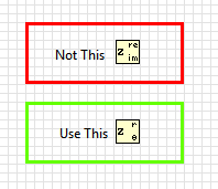
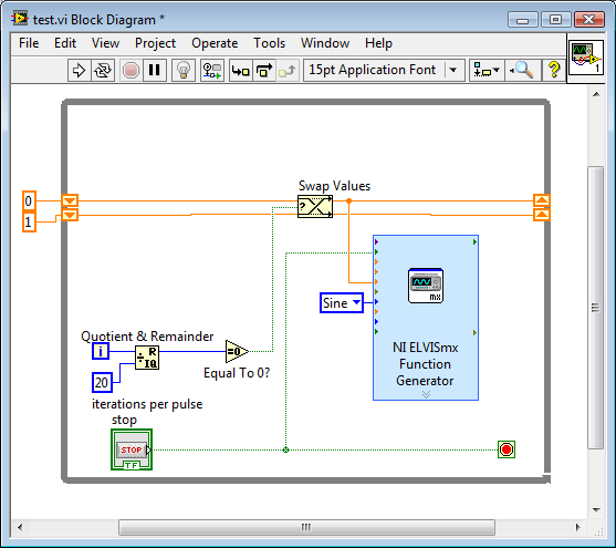
A way that comes to mind to use your generator to step on the odd numbered steps and insert the zero of the same numbered as follows. Quotient and remainder as a structure case will be.
Lynn
Tags: NI Software
Similar Questions
-
Count the number of 1 is present in digital waveforms obtained by converting the pulse signals.
Hello
I use Analogtodigital.Vi to convert the pulse of the sequences in digital.signals.I am able to get the representation of digital waveforms of impulses.
But how to count the number of 1 is present in the converted digital waveform. I want to count the number of 1 is present in the digital waveform converted.
Thanks in advance.
Have you tried the block scheme of similar to the Digital.vi of opening?
It creates an array 2D uncompressed 1 and 0, which is the binary 16 bits A/D conversion of each element in the array Y of the input waveform. You can use the DWDT digital Array.vi Boolean to convert a 2D Boolean table. Then convert Boolean values to 1.0 and summarize the array of integers. The sum must be the number of 1 bits in the digital waveforms.
Lynn
Note: The VI attached is saved in version 8.6. When I have it saved for the previous Version a warning was generated about the possible differences in the versions. Let me know if it doesn't work, and you are using which version of LV.
-
Restart waveform immediately start trigger
I create a waveform 50 ms with an SMU-5451 in SMU-1078 chassis with a controller of SMU-8840 running Labview RT. The waveform is currently triggered by a pulse of a counter of data acquisition because the timing of the wave must be closely synchronized with data on the acquisition of data collection. However, this approach is problematic because it is difficult to produce a continuous of the 5451 signal when it is triggered in this way. If the waveform is exactly 50 ms long, will miss the start trigger. I can tolerate losing at the end of the wave, but I can't tolerate having a gap in the output, and I need the waveform to start exactly on the edge of outbreak of 50 ms. I can configure the 5451 to accept a trigger start and restart the wave immediately rather than wait for the current iteration of the waveform to complete?
I guess I could use a complete the 5451 event to trigger the acquisition of data instead, but I guess there is a way for me to do what I want.
Are you familiar with the mode "script"? You might be able to use this example script:
script restartWhenTriggeredScript

  Repeat forever

    generate wfm

    break on scriptTrigger0

      Repeat forever

        generate wfm

      end repeat

    end break

  end repeat

end of script
Basically, the idea is that, when it receives a trigger, it stops the execution of the inner loop and finish the iteration of the outer loop. Then it will start again from the beginning and to the inner loop.
Please let us know if that fixes the problem.
-
generate the output waveform on 6259
Hello
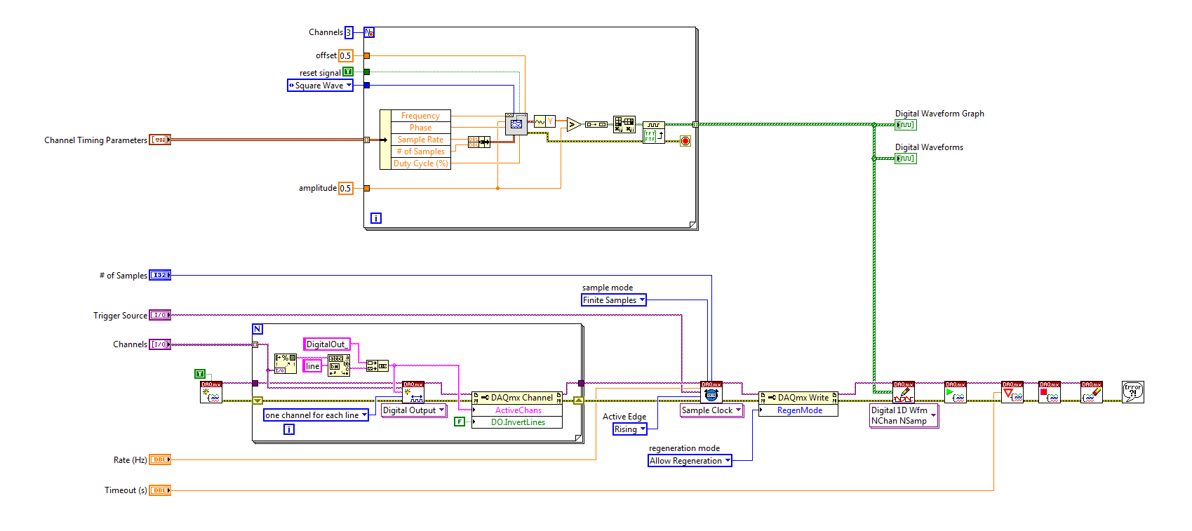
I would like to generate signals of "simple" digital square output 3 6259 NI Board of Directors of 80 Hz.
Because of the wiring of my test tool driven 6259 Board, I can't use the output of the meter, but I need to plug into 3 output lines.
I re-used an existing vi and made by a subcontractor, but the generated waveform on my DUT does not have the expected frequencies (although it seems OK on the generated graph). Indeed, there are some forms of square waves, but not continuously. A sort of "pomade" and "elected" frequency does not match the measured frequency. If someone has an idea to help me, I have not experience on labview yet!
Thank you!
You have 4 unique digital States aimed at bike. Each cycle produces 1 full period of each of your square waves. If you want the output to 80 Hz, you must set the sample to run 4 * 80 = 320 Hz clock.
The other thing you see on the scope is that there are short bursts of pulses with parent long time between bursts. The calendar during the bursts are what control tasks. The time between bursts is caused by using the button "run continuously. Also that according to them, you complete vi almost immediately rather than waiting until they run awhile. Put an end to the execution of vi initiates self-cleaning of LabVIEW. These things represent the time brief burst and the ISH between bursts.
-Kevin P
-
Pulse modulated CW with the PXI-5650 and PXI-6653
Hello
I'm trying to generate a signal CW of pulse modulated with the PXI-5650 as source RF and the PXI-6653 as the modulation signal. Basically, I'm trying to generate a simple radar waveform. It seems that it would be possible to use the synchronization Module (6653) to transform the RF output on / off on the signal generator (5650), but I do not know how to route the signals from one to another using LabView.
Has anyone tried this or something like this before? Can anyone please offer some advice?
Thank you!
-John
Hi John,.
Reading your post, it seems you want to use your calendar and map of synchronization to the RF output power, in other words, on Off Keying. OOK modulation is a feature built into the 5650. For more information, you can navigate through the NI RF Signal generators Help for devices-RF signal generators > NOR -> NOR 5650/5651/5652 overview-> Modes of Modulation and simply click on the Modulation Modes.
An example of this is found in the example Finder OR by navigating to the help-> find the examples in LabVIEW and then navigate in the Finder to example NOR material input and output-> Modular Instruments-> NI - RFSG-> signals-> RFSG 565 x Digital Modulation.vi.
Kind regards
Jason L.
-
How can I specify a delay generates a pulse meter?
Hi all
I have a question on the use of the meter to generate the pulse train. I did not how to program but I try the test panel in MAX and I see that it generates pulse train to certain rates and with a pulse duration. I think if it is possible to generate only a single pulse with given the duration of the impulse to sometimes after I start the job? I have a code to generate an analogue waveform, waveform of 35ms. I wonder if it is possible to synchronize the output of the analog waveform and counter such to 12.5ms after that the output waveform has started, I send this unique pulse from the meter port on. I have no idea how to do that, I think to use a delay but it is difficult to accurately control the time exactly 12.5ms.
Well, assuming DAQmx_Val_Low for the resting State, fires the meter will wait the initial delay and then generate a pulse at the time you request. Little time is not actually used in this example simple impulse.
From what you described, you must add a trigger to start your task of meter output (DAQmxCfgDigEdgeStartTrig) to you can set the meter to trigger off the beginning of analog output trigger. Set the initial delay on the counter for 12.5 ms. Start the task of counter in front of the task of the analog output. You should get your pulse 12.5 ms after you have started the task of the AO.
Best regards
-
filter the peaks on the signal from ECG pulse!, help!
Hello
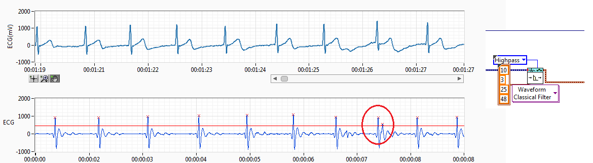
I have RCV of the ECG signal. I filtered the ECG signal and get the resource (interval between each pulse of ECG) records.
The source of the signal have noise I use a threshold but sometimes spikes of failure. Like the previous capture. Normally, if you get a pic of fault detected, I'll try to find this index to add to the left or right of the peak, normally I add to the lower value. This works if it has only a bad impulse between 2 good.
The problem come when I have more than a ridge between the two coupons.
Also, when the impulse of R a loss threshold I have trying to find the index and get 2 new reading making division 2 peak value.
I have attached the method I've used to adapt it. I only works if I have 1 Ridge added on real measures of R or pulse 1 loss R, when I have several pics no work.
I would like to hear an idea to make it work better. I don't like the idea of removing the value interval, I have 2 hours of reading and if I remove the values I have lower data outoput is why I tried to summarize or division of values to get the correct reading without losing any data.
Perhaps, there is any better filter for ECG of entry, so I have a R-own pulse and less noise between ECG pulses.
Any advice is welcome.
Best regards, Fred.
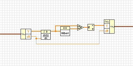
Almost. in the last step, you have extracted the real part of the complex waveform. Instead, you must retrieve the extent.
BTW, this idea isn't mine. I got from this article
http://www.ScienceDirect.com/science/article/PII/S0010482501000099
-
Generation of pulses using NOR-PXI-5421 FGen
Hello Sir/Madam,
Question:
We use the Funktiongenerator NOR-PXI-5421 and just want to generate a pulse, because it can be done in almost all cheap Funktiongenerator.
Unfortunately, I can't find a way to tell the Funktiongenerator to generate a pulse. I can generate Singals as I like, but don't know how to generate a single pulse.
Perhaps you have a program that gives me this opportunity.
Thank you for your support.
Hi Jens,
You can try to use the Council 5421 scripts. The following examples of LabVIEW: "Fgen Arb Script.vi" or 'Fgen switch between Waveforms.vi' use of script to generate signals, you can create a script that generates a single DC pulse of high level in the same way.
I hope this information helps you.
Best regards
Blase
-
Generate a single pulse on several channels of an external trigger high-speed DIO
Hello
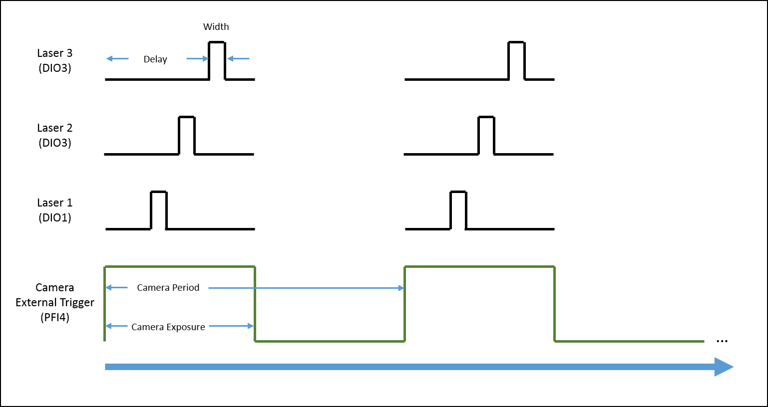
I'm trying to implement a system using a PCIe-6535 b connected to a high speed of SMB-2163 DIO. The system must be configured to work with a camera send a trigger (at the beginning of each show) to the PFI4 which in turn sends a single pulse on three digital output channels to lasers. Each output has its own specific deadline and the width. There is no counter on the SMB-2163, so I think I need to use Pulse Width Modulation (PWM). I saw this example and adapted to my system:
https://decibel.NI.com/content/docs/doc-8010
However, when the source to enter the DAQmx VI of sample clock is set to PFI4 (instead of the on-board clock) to receive input from the camera, changes in behaviour. The rate of sampling in the sample clock VI is ignored, and each element of the digital waveform is triggered. I need the sequence to complete each after trigger.
I am attaching a quick diagram of the sequence. Any suggestions on how I can get this kind of events triggered? (With the help of LabVIEW 2013)
Thank you
Mike
PLATES
The external signal must be configured as a trigger for digital startup rather than the sample clock. I do not think the 6535 redeclenchables supports digital output, so you don't have to restart the task after receipt of each trigger (something like this, however you can improve performance by committing to the task by using the task of control DAQmx before entering the loop).
Best regards
-
OR PCI-6542: Creation of dynamic waveforms using the HSDIO library
Hello!
I have problems to understand how to create waveforms using the HSDIO library to run on a card PCI-6542. I need to create a program that activates a channel for 12.5 microseconds, waiting for a while (i.e. 100 samples) and activates another channel to 12.5 microseconds.
This program must be used in a Multielement ultrasound system.
Here the example of dynamic generation program that transforms the channels 0-2 on 1024 samples.
/************************************************************************
*
* Example program:
* DynamicGeneration.c
*
* Description:
* Generates a simple model on the specified channel.
*
* Pin connection information:
* None.
*
************************************************************************// * Includes * /.
#include "niHSDIO.h"./ * Sets * /.
#define WAVEFORM_SIZE 1024int main (void)
{
ViRsrc deviceID = 'Dev1 ';
ViConstString channelList = "0-2";
ViReal64 sampleClockRate = 50.0e6;
DataWidth ViInt32 = 4;ViUInt32 waveformDataU32 [WAVEFORM_SIZE];
ViConstString waveformName = "myWfm";
ViInt32 timeout = 10000; / * milliseconds * /.ViSession vi = VI_NULL;
Error ViStatus = VI_SUCCESS;
Bruno errDesc [1024];
ViInt32 i;/ * Initialize generation session * /.
checkErr (niHSDIO_InitGenerationSession)
Deviceid, VI_FALSE, VI_FALSE, VI_NULL, &vi));/ * Assign channels for dynamic generation * /.
checkErr (niHSDIO_AssignDynamicChannels (vi, channelList));/ * Set up the clock sample parameters * /.
checkErr (niHSDIO_ConfigureSampleClock)
VI, NIHSDIO_VAL_ON_BOARD_CLOCK_STR, sampleClockRate));/ * Query the data Width attribute * /.
checkErr (niHSDIO_GetAttributeViInt32)
VI, VI_NULL, NIHSDIO_ATTR_DATA_WIDTH, & dataWidth));
/ * Fill the waveform with ramp data * /.
< waveform_size;="">
{
waveformDataU32 [i] = i;
}checkErr (niHSDIO_WriteNamedWaveformU32)
VI, waveformName, WAVEFORM_SIZE, waveformDataU32));/ * Start the generation * /.
checkErr (niHSDIO_Initiate (vi));/ * Wait for all the generation * /.
checkErr (niHSDIO_WaitUntilDone (vi, timeout));Error:
If (error is VI_SUCCESS)
{
/ * Print result * /.
printf ("made without error. \n") ;
}
on the other
{
/ * Get the description of the error and print * /.
niHSDIO_GetError (vi, & error, sizeof (errDesc) /sizeof (petitioner), errDesc);printf ("\nError encountered\n===\n%s\n", errDesc);
}/ * log * /.
niHSDIO_close (vi);/ * prompt to go out (for the popup console windows) * /.
to continue...\n");
GetChar ();error return;
}Issues related to the:
How can I change the values in waveformDataU32 to create market reports (instead of just always on)?
How to select the channel waveformDataU32 is applied to the?
Thank you!
Zachary Geier
The waveformDataU32 table is an array of 32-bit integers. Each bit corresponds to a line on the device. On the first clock cycle, this program outputs:
0000 0000 0000 0000 0000 0000 0000 0000
Then it displays the following, changing at each clock Pulse:
0000 0000 0000 0000 0000 0000 0000 0001,
0000 0000 0000 0000 0000 0000 0000 0010,
...
and so on all the way up to 1023:
0000 0000 0000 0000 00000011 1111 1111
In the example that you include at the bottom, you set the least significant bit (LSB) to zero and one, actually only change one line on the output. To change all the lines, you must instead use 4 294 967 295 or 0xFFFFFFFF:
< waveform_size;="">

     < 200){="" if="" sample="" number="" is="" less="" than="">

          waveformDataU32 [i] = 0;     Disable channels 0-2

     }

     else {}

          waveformDataU32 [i] = 4 294 967 295;     Otherwise turn on all channels to 800 samples

     }

} -
Hi all
I'm going through the phase of my small vi debugging and found an inconsistency that makes no sense. My goal is to generate a single TTL pulse as soon as I discovered a passage by zero of a sine wave. So, I generate a simple sine wave and send a logic true to the block which supposedly should initiate a TTL pulse generation. I first tested at 1 Hz sinusoidal and pulse TTL of ecu 1 Hz. I then put my sine funnction at 5 Hz, but I always only TTL signal of 1 Hz, instead of 5 Hz (1 pulse each time by resetting a sinusoid at 5 Hz).
Can anyone suggest where the problem is maybe?
Thank you in advance!
I think that your problem is easily explained by a single sentence in the help for the VI of passage to zero: "If wire you a waveform value or a dynamic data type value at the point of data entry, this VI evaluates only the first value of the input data."
-
How to create impulses cause a pulse width Variable AND at the same time
Hi all
I have a NI PCI-6251 that comes with 2 counters, a FREQOUT port and then some DIO, DAC and ADC. I want to trigger a pulse of variable width (easy to do with two counters) and a frequency closed, exit at the same time. So, I want to end up with a line that will display TOP for some variable time, while the other exits a train of pulses for a time variable. It is easy to do if you have 4 counters but I don't have one. Does anyone have an idea to implement these two things AND making them trigger at the same time with the PCI-6251 card?
The line is high for as long as your pulse train controlled?
If so, set up the first counter as output pulse, configure the 2nd as output continuous meter but with the internal of the first counter output as its trigger to pause (pause when it is low). Start the 2nd meter before the first.
If not, you will need to use the digital output to replace at least one of the counters (max sampling rate is 10 MHz, so this would give less resolution compared to the time base of 80 MHz counters). So you would simply write the waveform predetermined in the buffer and he clock at the desired rate and the number of samples to give the signal that you want. You need to generate some other subsystem as FreqOut clock.
Best regards
-
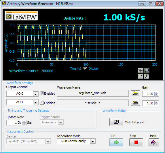
How to generate a pulse with the signal generator?
Hello
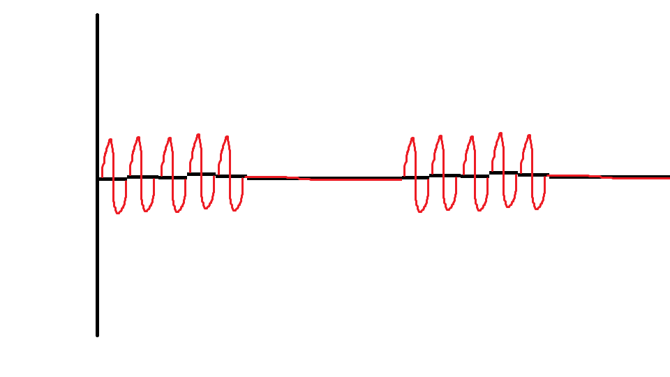
I would like to ask if anyone knows how to use the Elvis platform to generate a regulated pulse wave?
It should look roughly like the picture above. A sine wave with the regulation.
Anyone who can answer my question please respond to my post.
Thank you.
You are using LabVIEW to generate the waveform or using the Soft front panels? In LabVIEW, you can use the express VI generator function and specify the Type as "Sine". Then, simply change the amplitude of the sine wave. During the actual pulse, the amplitude would be what you want (i.e. 1 V) and while the pulse is idle, set the amplitude to 0.
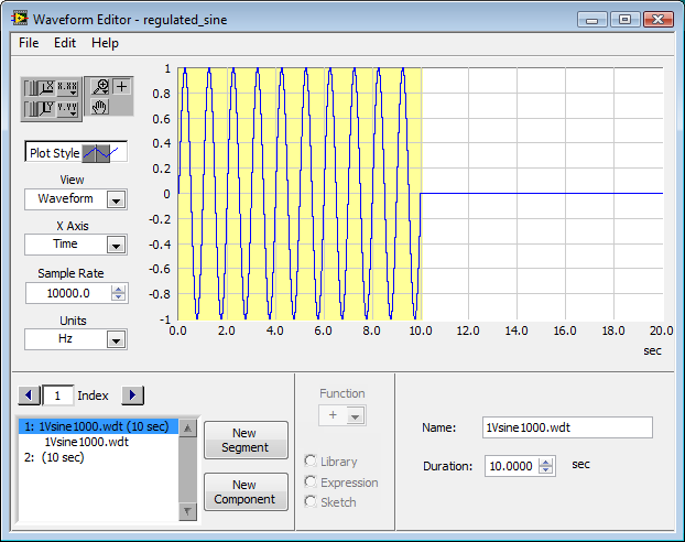
If you use the soft front panels, you can use the Waveform Editor to create a waveform that includes a sine wave for the length of your pulse and then the values of '0' for the rest of the time. Then use this waveform in the flexible front of the arbitrary signal generator. Simply create a component of sine as the first part of the wave and then add another element to a level DC '0' for the rest.
-
How to generate a single pulse with DAQmx
I need to generate a single pulse using DAQmx. Many of the example of the AO screw blood generation using waveform (multi) .vi buffer generation. This VI generates a + / amplitude. I want that my pulse to go from zero to a positive amplitude. How to achieve this?
Thanks in advance.
What amplitude and what pulse width?
If you have found an example with regeneration, to get a unique waveform, you can disable the regeneration and just do a single entry.
-
How can I more easily generate a pulse of digital output of finite length?
Hello
I need to open and close the two pneumatic valves using a TTL output (without load current or the output power) using a PCI-6280 or PCI-6601. The valves must open almost simultaneously and closing after different amounts of time elapsed (millisecond level timing, maybe 100 microseconds-level timing at worst). My current plan is as follows:
-Create a task with two digital outputs (type of waveform) and another task with a counter that generates a frequency set by the user (I know I can use the generator frequencies on one of these cards, but I would have preferred a counter - the best selection of frequencies).
-Wire the output of the counter at the entrance to clock two digital outputs.
-Output of the meter is digitally triggered by another digital channel which I use to control if the pulse goes out. Through its counter node, it is programmed to be redeclenchables.
-Two digital waveforms are drafted who have both consist of unique active high pulse (i.e. signals go ' down (for the amount of time user-defined) - low ".")
-These signals is written to their respective ports and their tasks have started, as is the task of the meter.
-Whenever the user wants to open taps, digital triggering is sent up and then back to low (this can be done with synchronization software, because it is not exactly when the fire valves). Whenever the user wants the valves open for a different period, different digital waveforms are generated and written in the buffers of the digital output channels.
My problem is that it looks like a lot of effort for me to go and I wonder if there is a much simpler solution, that I don't know everything. You can program a computer to produce a pulse of finite length? Is there a faster way to program a digital output for that channel?
Thanks to anyone who responds to their help.
It is certainly instructive. Thank you.
The thing is, I have only six total counters to work with and I have a lot of time to do things. To use these solutions, I would need to use 4 or 6 account counters required to my needs.also that I would need to synchronize their departures.
Overall, I stick to my method for now - less system resources and synchronization can be don by using the same meter of finished output clock and not to use a trigger to all.
Once again, thank you for your help so far.
Maybe you are looking for
-
driver missing for Pav HP dv6700 entertainment pc coprocessor
Hi all.. I know there have been several messages on this problem with windows 7, but I'm a noob and need a direct link to where I can download the driver for my HP Pav entertainment pc dv6700 coprocessor. All I can tell you other than the driver is t
-
How can I stop intrusive adds on my screen
How can I stop intrusive apple adds on my screen?
-
Route transfer to phone office google map
I have several routes on my Mac in Yosemite OS X for a three weeks bike ride. Previously, I used email to send to my phone, but I do not use this service on my iPhone 5 more. I read where you go to "notifications" in the settings, select Google maps
-
How to disable specific columns in a table
Hello world There are two buttons in my code (SHIFT and general). When I press the SHIFT key, general column should disable & grey outside, but all three move the columns (Shift1, Shift2, Shift3) should be in an editable state. Like the picture below
-
running explore under RunAs is not working now
I have problems with RunAs works with Explorer. RunAs works on system restore and EVENTVWR. MSC under that same account limited but not with Explorer as before. The Explorer window never appears. Recently, I ran SFC/scannow and I was wondering if it