Single pulse TTL
Hi all
I'm going through the phase of my small vi debugging and found an inconsistency that makes no sense. My goal is to generate a single TTL pulse as soon as I discovered a passage by zero of a sine wave. So, I generate a simple sine wave and send a logic true to the block which supposedly should initiate a TTL pulse generation. I first tested at 1 Hz sinusoidal and pulse TTL of ecu 1 Hz. I then put my sine funnction at 5 Hz, but I always only TTL signal of 1 Hz, instead of 5 Hz (1 pulse each time by resetting a sinusoid at 5 Hz).
Can anyone suggest where the problem is maybe?
Thank you in advance!
I think that your problem is easily explained by a single sentence in the help for the VI of passage to zero: "If wire you a waveform value or a dynamic data type value at the point of data entry, this VI evaluates only the first value of the input data."
Tags: NI Software
Similar Questions
-
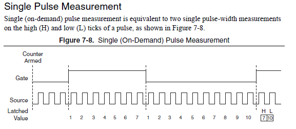
single pulse width measurement
Hello
I'm trying to measure the duration of a single pulse using ctr0 on an SMU-6361.
The signal in the attachment Capture7.jpg, goes PFI 9, ctr0 door.
The problem is that the counter see ' s the front up and stops. The pulse width is not given as can be seen in the output (Capture8.jpg).
I get the same results by using Meas_Pulse_Width.vi example.
Is something wrong with my SMU-6361?
Oh, I think I know what it is.
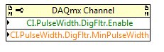
Change the task "pulse width" (a single pulse of height) instead of "Pulse" (the high and low time of a pulse repetition measures). Change the DAQmx Read to use Ctr > single sample > DBL (instead of pulse). Change the property filter node digital to use the corresponding properties of the "pulse width" (the filter is still necessary):
The task of the pulse was not period initially because you receive a series of noise pulse repetition (and so it was a very low period). With the filter, this time since the noise disappears now and the single pulse did not finish measuring the pulse (which requires a high and some time):
For the record, I agree that it is confusing that there is the "pulse" and "Pulse" measure and they do different things.
Best regards
-
Generate a single pulse on several channels of an external trigger high-speed DIO
Hello
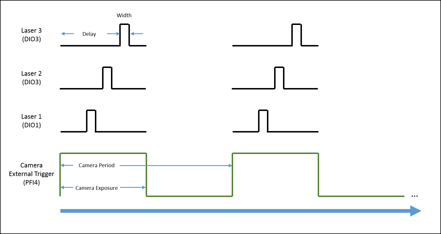
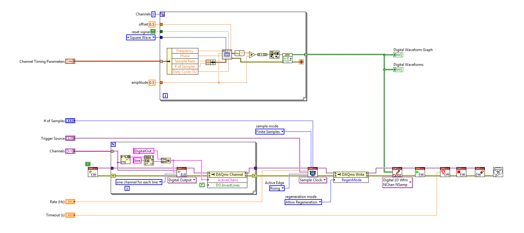
I'm trying to implement a system using a PCIe-6535 b connected to a high speed of SMB-2163 DIO. The system must be configured to work with a camera send a trigger (at the beginning of each show) to the PFI4 which in turn sends a single pulse on three digital output channels to lasers. Each output has its own specific deadline and the width. There is no counter on the SMB-2163, so I think I need to use Pulse Width Modulation (PWM). I saw this example and adapted to my system:
https://decibel.NI.com/content/docs/doc-8010
However, when the source to enter the DAQmx VI of sample clock is set to PFI4 (instead of the on-board clock) to receive input from the camera, changes in behaviour. The rate of sampling in the sample clock VI is ignored, and each element of the digital waveform is triggered. I need the sequence to complete each after trigger.
I am attaching a quick diagram of the sequence. Any suggestions on how I can get this kind of events triggered? (With the help of LabVIEW 2013)
Thank you
Mike
PLATES
The external signal must be configured as a trigger for digital startup rather than the sample clock. I do not think the 6535 redeclenchables supports digital output, so you don't have to restart the task after receipt of each trigger (something like this, however you can improve performance by committing to the task by using the task of control DAQmx before entering the loop).
Best regards
-
count the pulses ttl only on 2 V
Hi I have a problem while I was trying to count a pulse ttl using the DAQ Assistant. The problem can be simple, but I just can't solve that since I'm new to LabView.
There is a TTL pulse produced of our ODA that is about 30 ns width, 5V. I want to use LabView to perform the count of photons. But because of the noise, I want to put a number limit of 2V, so the software one count higher than 2V TTL pulse. But I can't do that. There is no option to set the limit.
And our material is BNC-2110 and PCIe-6323.
Can someone help me with this? Thank you.
For a counter entry, the minimum voltage for logic there is 2.2 volts - a ttl level. And no, you can not adjust higher.
-
How to generate a single pulse with DAQmx
I need to generate a single pulse using DAQmx. Many of the example of the AO screw blood generation using waveform (multi) .vi buffer generation. This VI generates a + / amplitude. I want that my pulse to go from zero to a positive amplitude. How to achieve this?
Thanks in advance.
What amplitude and what pulse width?
If you have found an example with regeneration, to get a unique waveform, you can disable the regeneration and just do a single entry.
-
How can I use two counters to capture a pulse ttl for a specified time
Configuration: Card counting 6062 PCI w / BNC 2121 Board running under LV 9.0 PerkinElmer Avanlance Photodiode (SPCM-AQRH-13)
I searched through the forums and fell on the theme of framing an image while collecting signals from a source for a specified time.
The example in terms of falkpl in 2005:
"
Dismal Hello,
I'll try to point you in the right
direction to start coding the application, but do not forget my
suggestions have to be modified to your specific request.For
the task output redeclenchables finished meter you need to
your counter seconds in this application, I suggest to take a look
in the Finder example in LabVIEW ('Help' are examples) and less
DAQmx hardware entry & exit"" generating digital impulses. Here,
you will find some Gen dig Pulse - Retriggerable.vi. You can use this for
Create your door 4 pulses ms it's over (not a pulse train) and
redeclenchables (for each time you go to the next step.In
regards to the configuration of the first counter, there are several things to
consider, and I can offer initial help to get set up. You
in-house allows to route internal CTR1 (4ms of pulse) output for your CTR0
Door to measure only during the time. Here are additional
Info to do this in LabVIEW. The source of your task of edges ABOVE County
will be the TTL signal you are measuring and counting. It comes
on the PFI line that corresponds with CTR0 Source.When
you make a measurement finished with CTR0, you will take only heads while
the door is high and your source has a rising edge. You can set the
measure over to start on a trigger, which is not clear in this
for example, that you have identified. Since you know that you have a finished 4ms pulse
time to measure, you can set the duration of your measure
as a result.I found this
Forum which may help some, but the coding is
textual. I hope this can give you a good starting point for
programming. -
Measurement of voltage deferred with a start from a pulse TTL (PCI-6251, OR DAQmx)
Hello
What I do: gain a measure of tension after a certain period of time (order of microseconds) when we observe a TTL pulse, lasting about 1-100 microseconds. What are the options I to do thins?
PS. If this problem is solved in a C code example, please point me to the right direction. I saw examples of NOR-DAQmx, but not a not spot something like this.
Hi hum-human resources management.
The example of DAQmx ANSI C Analog In\Measure Voltage\Cont Acq - Ext Clk - Dig start shows how to use DAQmxCfgDigEdgeStartTrig() to activate a digital start trigger. It also illustrates the continued acquisition, clock to external sampling and all events of samples N; for a simpler starting point, look at analog In\Measure Voltage\Acq-Int Clk-Anlg start and try to convert to using digital analog INSTEAD of triggers.
However, this will start acquiring exactly when the trigger occurs, not after a period of time fixed. Use DAQmxSetStartTrigDelay() and DAQmxSetStartTrigDelayUnits() to add a fixed delay between the trigger and the beginning of the acquisition. Help OR-DAQmx C reference (which should be on the start menu under National Instruments > NOR-DAQ) lists the valid values for the property of units.
Brad
-
How to generate a high TTL and a weak pulse TTL using the USAB daq card
Hi all
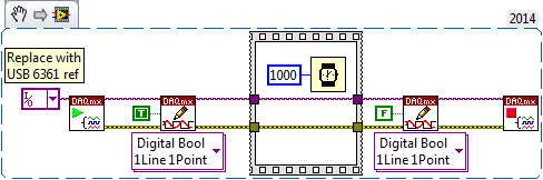
I have usb daq 6361, how do I generate a TTL high and low pulse in labview to trigger my camera.
Thank you
Here is a code DAQmx to start your 6361, a digital output the value True (high TTL), wait a second, then set it to False (low TTL). Have you tried to connect your device to your PC and pull them to the top of MAX? He must "see" the device, and you can manipulate its ports to test. Indeed, the name MAX gives your device is what you put into this first constant of e/s on my example (if you click the drop symbol, you should see a list of devices found as MAX).
Bob Schor
-
Generate a single pulse in response to an external trigger
Hello
I have a PXI-5412 arbitrary signal generator, a simultaneous sampler PXI-6115 and PXI-6652 synchronization module. I would like to the PXI-5412 to produce a square pulse and PXI-6115 to acquire a set of data in response to a digital triggering module. (In the future I might want to generate a slightly more complex Wavelet, but for now a square pulse will do).
I used This example as my reference. So far, I used successfully OR Sync to initiate through DAQmx data acquisition when arrives the trigger. However, I can't do the same thing with the generation of pulses. I've been able to get NOR-FGEN to produce continuous square waves, no simple impulses.
The-OR-FGEN Arbitrary Waveform Generator VI Express lets me select finishes generation Mode. How can I configure the same screws no express?
While we are at it, is there a better way to accomplish my synchronization the procedure I described (DAQmx, NOR-Sync + NI - FGEN)?
Thank you!
You can get this set as a single trigger mode. You could also learn how to express VI which make a right click on it > open Frontpanel.
-
How to generate a single pulse using PXI-4461 in Labview
I need to generate a single positive pulse is 100ms using an OD on the PXI-4461 with DAQmx Labview
I have trouble getting the exact time of the pulse.
Help, please.
Thank you.
He works, see attached pattern obtained.
Thanks to NI Applications Engineer ally Finney for example.
-
Pulse TTL-PCI-6503 write in a log .txt file
Hello, I need to connect the PCI-6503 data output to a log .txt file. This PCI-6503 map reads a pulse sent from another PCI-6503 located in another computer. I want to just save the .txt file if a pulse is received. I know how to create and write to the .txt file, but do not know how to write the DAQmx data in this file. Could someone help?
Thank you in advance!
Hi a2h,.
To only write when there is data emerging from the Daqmx read, you can use the table Emply?. VI to determine if there are real (like the pulse) from the unit and then data of yarn that a structure of case that will write to a text file in the case of false.
Peter W.
-
OR-SCOPE exit on PFI0 or PCI1 5122
Hello
I'm a bit new to NOR-Scope. I have a card 5122 and want to output a single pulse TTL on PFI0 or PFI1. I don't want to not be triggered or something. Basically, on my face, I have a button that says "Pulse" and when I press the appropriate IFP will display the single pulse. I tried to use NIScope export Signal.vi but can't seem to make it work.
Thanks for any help!
Steve
Hi Steve,.
I want to assure you that I understand you. You are eager to get a signal on one of the PFI lines when you reach begins its acquisition. If that is correct, you can use the VI of Signal to export and choose to export the trigger to start. This should output a pulse when begins the acquisition. Let me know if it works for you.
-
create 4 pulse digital output at the base of the ttl input signal
Hello
I am a beginner in Labview and would welcome advice on how to solve the following problem.
I'm setting up a train of pulses TTL and would like to send in Labview as input. Each falling edge detected on the input signal, I would like to as Labview to generate 4 pulse digital output. For each output pulse, I would like to be able to specify the period and duration. The image should illustrate more clearly, with the figures showing the expected scale.

System: NI PCI-6733 data acquisition card, Labview 8.5
My daq card has 2 timers 24-bit and 8 e / s digital, but I don't know what the best approach is to create between the pulse output of 4 to 8 of this precision... should it be handled at the hardware or software level? And how would I go about it
Thank you
-Sidney
Hi noli.
I found the problem, in fact PCI-6733 support only avoiding the digital output. The timing of software is limited to 1 kHz in case better.
I'm sorry, but this function is not possible with a PCI-6733.
Concerning
-
Photon counting using the FPGA of the series R. problem generation TTL signals
Greetings,
I try to use the R series FPGA to read and count the pulses TTL of a discriminator (count of photons of the Hamamatsu C9744 unit) connected to a PMT (Hamamatsu-H7422P-40). The release of PMT looks fine (signal.png H7422P-40) but the discriminator wasn't able to generate corresponding TTL 5V pulse. There was some scattered and random spikes, but nothing significant. Instead, the only stable the PMT signal is a single + 5V pulse no matter how, I adjusted the PMT (C9744 output.png) control voltage. The PMT and the discriminator is connected by an ordinary BNC cable 50 ohms.
I am really confused because it was supposed to be a really simple installation. Anyone have a similar question or have similar Instrumentation (but no problem) configuration? Comments/suggestions are greatly appreciated.
Thank you very much in advance!
Hi Kelli,
Thanks for your help. Sorry it took so long to get back to you.
I actually found the question. The discrimination of the Hamamatsu unit level is set too high that all signals got filtered. After adjustment of the threshold of manuallyt, I was able to get the camera TTL pulses. And 7842R worked correctly for count impulses. Everything works fine now. Thanks again for the input.
-
VI to convert input signals NI 9402 in a RPM value, based on the frequency of the pulses
Hello
I'm looking for a VI convert an input signal NI 9402 in a RPM value, based on the frequency of the pulses. Is there such a thing that exists in the library of national instruments?
I run LAbview 2014 integrated control and monitoring on on a cRIO 9802 high performance integrated system with NEITHER 9402, 4 channels, 50 LV, LV TTL Module input/output digital, ultra high speed digital i/o for the cRIO module.
Any help would be greatly appreciated.
The easiest way is to use the FPGA to get the time between the edges of your pulse increase (shift registers to maintain the current situation and the time will be necessary). This will give you the period. If it's a single pulse per turn, then the number of laps is just 60/T, where T is the time in seconds.
Maybe you are looking for
-
Any available adapter to allow the loading and use all the earphone for iphone 7?
How can I recharge my Iphone and used my set for Iphone 7 ear piece? When I load my iphone 7, the port of lightning and I can't use the the ear piece. Please notify any available adapter?
-
How to close multiple windows of firefox (not mulitple tabs)
I often have several internet messaging Windows Open (often each window has several tabs). I would like to be able to leave all the windows with just a single closure of firefox. Currently, I can close each window with multiple tabs with a single lar
-
After update iTunes 12.3.3.17, I don't see the option in the APP store right
Hello After updating to iTunes layout 12.3.3.17, tea from the APP Store was offside on the right so I don't see that option in the APP Store right, each icon in the APP Store is larger than the previous version. Please help me, thanks! OS: Win 7 64 b
-
HelloI downloaded and installed these updates released August 25 (kb976569 - kb982168 - kb979909 - kb983583), but when I check the other updates, I see them once again, and when I want to install them again, they get faild, anyway I see them on each
-
Optiarc DVD RW AD-7590AS ATA DEVICE__CODE 19 REGISTRY has FAILED OR IS DAMAGED? YELLOW
RECENTLY BOUGHT THE DVD/CD RW WITH NO SOFTWARE TO INSTALL, AFTER INSTALLATION WAS COMPLETE AND RESET THE SYSTEM NEW HARDWARE WAS FOUND BUT COULD NOT BE INSTALLED BECAUSE OF THE ERROR CODE 19.