PXI-2569 - relay to armament
Hello
Looking for the relay for the PXI-2569 Council specification, I've seen the part number IM42GR for this component. This relay of Axicom has a bistable coil type.
I just want to confirm that this relay away this last position during a power failure or a power command in PXI chassis.
Thank´s in advance
Hello!
According to this KB, lock relay, which is kind of the PXI-2569present relay, relay keeps its last position if the frame loses power.
Kind regards.
Tags: NI Hardware
Similar Questions
-
Calibration of the PXI - 2548 relay module
#1) where can I find the date when my PXI-2548 relay module was first calibrated?
(#2) y has different ways to calibrate this relay module and if yes what are?
(#3) combien of time should this relay module be calibrated?
Thank you
Julian
Hi Julian,.
NI PXI-2548 requires no calibration because it does not all electronic components that can be calibrated. Therefore, there is no calibration carried out, there is no way to calibrate the module, and there is no timetable for calibration.
Note that you can compensate for the loss of insertion of the passage on a per path basis. These offsets typically include loss through cables and are carried out when the Board is placed in the system. It is more than compensation compensation for 'switches + connectivity' system rather than a Board calibration; It is dependent on the system. I recommend you do this compensation measure before proceeding with automated tests.
I hope this helps!
Chad Erickson
Switches Product Support Engineer
NOR - USA
-
OR TB-2605 terminal block for the NI PXI-2503 relay card PIN GND interconnection?
I use the relay Board NI PXI-2503 and the NI TB-2605 terminal block to impliment some of interconnections, my question is on the Terminal it is a GROUND terminal on the GND PIN. What electric pins or card background basket or internal relay Terminal this 'point' interconnection to?
Hello gene01,
I don't directly know what this PIN connects to. Following the trace, that looks like it is connected to the mass of the chassis as the 2503 itself does not have a grounding pin. I have this will confirm for you, but is there a specific reason for your application need you to do this?
-
Hello
does anyone know the number of K-related relay relay channels? I can't find it in the documentation.
THX
Wolfgang
Finally I do the job to measure the relay by hand:
K0... 23 = CH0... 23
K24 = BC01
K25 = BC23
K26 = BC02
K27 = CJS
K28 = 1WIRE
K29S = HISELECT
K30 = AB0
K31 = AB1
;-)
-
I'm creating a test set-up and we probably intend to use the PXI-2568 (and the mating cable) to connect, but want the cable directly into my test setup. I think that there are a few standards D - 62, and I do not have the PXI-2568 module still to test.
What (for example) a connector suitable for mating with the PIX-2568 cable?
http://www.digikey.com/product-detail/en/Te-connectivity-amp-connectors/5749639-1/A31926-ND/808312
Hi Osbock,
The connector on the PXI-2569 is a standard 62 connector pins D - SUB, male, so it turns out that the connector that you found should work for your test setup.
I looked at the section "Accessories" of the data sheet and a female front connector, it says 62-pin D - SUB, female of any manufacturer, so I expect the same thing to the male connector on the other end of the cable.
-
NI PXI - 8361 PCIe card not detected
Hello community,
I'm trying to mount this PXI system and running on a computer that is running Windows 7 Enterprise 32-bit. We already have a system running on another computer running Windows XP 32-bit.
Chassis OR PXI-1036
OR PXI-8360 controller connected to the PC via card OR PXI - PCIe-8361
NI PXI-6220 multifunction data acquisition
NI PXI-2570 relay module
OR PXI-GPIB
I spent a day or two trying to download different drivers and could see the NI PXI-PCIe 8361 NI Max card, but I did not see the chassis. I then tried uninstalling all software of OR, so that I could do with care that it was installed in the proper order:
1. shut down the PC and PXI system, disconnected from the PXI from your PC system.
2 installed Labwindows + Labview (Developer Suite 2011)
3 installed NI PXI Platform Services CD that came with the PXI (Version 3.2.3) system
4 installed 'System NI Driver Set 2014.05' a Flash disk that came with the PXI system
5. off the PC and then on the PXI system and connected to the computer.
After turning on the PC, I see that MAX NOR does not seem able to recognize the NI PXI-PCIe 8361 card as I have before.
At this point, I thought that it would be better to ask the community for help rather than start abritrarily updated drivers again.
Thing some Chris! HM this is interesting. Looks like this might be a BIOS problem, in accordance with the following article -http://digital.ni.com/public.nsf/allkb/81A788D0076390FA86257BF9002F9983?OpenDocument. The link also shows that some BIOS update the troubleshooting steps. I hope this will redirect you to a resolution.
-
entry 100 pin voltage measure switching device
I have a number of 100 harness cable pin I need to check the output voltage on. I need to be able to select the two pins (tension and back) and move them towards a pass to tension. Unfortunately, each cable is unique, so I have to be able to select any combination of possible pin pair. Any ideas on the architecture of mux/switch to use is appreciated.
stratcat wrote:
If I am correctly each pin will go to two of the columns. So I turn on a PIN (side) on the pin (back side) column an and the other two column. Looks like my thoughts once I made the first post of the use of two PXI-2569 cards would also work. Choose the high pin on one card and the PIN back on the other.
In fact, I told you 1 1 column axis. Then you have a column to the side as high DMM and a column for the low side of DMM. Since you have 4 rows, you can easily connect any axis of part and on the other of the DMM when you plug a different pin on the other side of the DMM through the matrix.
-
I have a PXI2567... LabVIEW 2014.
I use the vi below (check relay.png) I created in a Subvi. I call this Subvi several times now in my main vi. The aim is to close 5 or 6 different relays at the same time. When I get to the 5th relay is not shut it down. I can tell because that its supposed to drive a motor and the motor does not turn. If I open the relay Subvi and do the ' device Boolean reset ' true and put in the relay that controls the motor... Run it... it works... BUT all the other relays drop-out. I know it's supposed to happen but I don't want to give up. I need their participation for my test to succeed. I first thought that I was using the wrong or pass the screws and entered MAX... Pinout for my device. He suggested a vi I joined (niswitch connect chs.png) but this vi wants to connect together the 2 channels. All I want to do is close my relay. I have the relays configured at the hardware level as indicated in the joint (PXI2567 independent.png).
Issues related to the:
Am I using the right NOR pass vi for pxi 2567?
How much current should my supply turn off to fill the 5-6 pxi 2567 relays at the same time? Can't find that ANYWHERE in the specifications.I use "K1" to close a particular relay. MAX uses ch1. When I put ch in my Subvi I get an error and need to revert to the use of 'K '.
Thank you...
The niSwitch control relay VI is the correct VI to use to close the relay in the PXI-2567 module independent topology configuration. Did you ensure that the relay is not closed by turning the switch off Soft Front Panel? If you look at the relays (listed of k0 k63) you can see if they are open or closed after executing your Subvi using the correct relay name (IE k4). You can also check the relays operate by a channel that connects to the corresponding com (ch0-com0) and checking the position of the relay changes to open to closed.
Regardless of your current diet, the switches should open and close in the map otherwise that it is connected to them, so I doubt that's the problem. There is a current maximum specification, above which the relay could get damaged, but as long as the module is in the chassis and the chassis is powered on the switches should open and close.
-
Handshaking DMM with multiple switching devices - DAQmx error
Hello.
I am trying to create a loop of the handshake with DMM (PXI-4071), SWITCH (PXI-2569) and MUX (PXI-2575). The three instruments are in segment 2 chassis PXI-1045 (locations, 8, 9 and 10) and I use the ways of PXI trigger in the triggers of the route.
I followed the article NOR 'Multimodule Scanning with National Instruments switches' - I modified the example NI SWITCH "niSwitchDMMSwitchHandshaking" to set up another SWITCH, but when I tried to run the example, I got an error:
0xbffa6b9a - no lines recorded could be found between the device in the road. (screenshot pop up is in the attachment). It is the function of niSwitch_InitiateScan to the second switch that returned an error.PIX trigger change has no effect.
I tried the CVI and LabVIEW examples with the same result.
I even tried to use two 2575 MUXes - same result.Can someone tell me what I am doing wrong?
Hi Pavel,
I checked that the component that controls the routing of the TTL for the PXI is included in NOR-DMM 3.0.2 (latest version as of 06/14/2010). NOR-DMM 3.0.1 contains an older version of the TTL routing code and will therefore place several comprehensive lines scanning advanced on the same trigger.
Unfortunately, the component which controls TTL routing is one of the constituent elements of the software installed OR lower, and thus we do not expose it to the user. For that to work, we would need to uninstall almost all the software components of NOR, which is a major undertaking. Here's what I recommend instead:
For now, we will Garland triggers one switch to another. This will allow us to start development in OR-Switch; as soon as OR distributes a program, you simply change the triggers as they all point to the same TTL line. This will allow switches to operate in parallel rather than in series, and the passage of the switch of your project can run faster.
If we have to absolutely exploit the switches at the same time, I would recommend either uninstall all software of OR or get a machine with a fresh install of XP and then install not newer than 8.9.5, OR DMM 3.0.1 DAQmx software and NI - Switch3.8.
As I mentioned earlier, NEITHER is aware of breaking backward compatibility and we are committed to reintroduce the old features in a future release of the pilot.
Keep this thread bookmark and post back in a month or two and I'll let you know if we have any updates.
Have a great day!
-
How to identify a particular relay on a PXI-2532 module
I have a defective relay on a map of PXI-2532 matrix. I don't know who it is, but I do not know how to identify on the map itself relay. I would like to replace it. Any information would be appreciated.
With a few head scratches, it helped a lot. Thank you!
-
error:-1074130544 using the PXI NI 2569 map
Hello
I use the testbed 4.1 for the execution of the sequences. I use NI 2569, 2529, 4070, 6229, 4110 PXI cards in my NI 1045 chassis and I use my own COM server for the test bench. The COM server has the implementation to call the driver API provided by OR for different PXI cards. Now, I have improved my versions of all my PXI cards drivers. My driver versions are currently
OR Switch: 3.6
DMM OR: 2.7.2
NEITHER series: 3.3
NEITHER Daqmx: 8.6.1
OR Visa: 4.3
Traditional DAQ: 7.4.4 (inheritance).
I used to use versions of the drivers such as:
OR Switch: 3.0
DMM OR: 2.5
NEITHER series: 3.0
NEITHER Daqmx: 8.0
OR Visa: 4.3
Traditional DAQ: 7.4.1 (inheritance).
Now, the question was when I called you my code niSwitch_Connect() function, it allows to connect the switches correctly and returns a value when I was with older versions of the driver. But after upgrading my driver version now I get the 1074130544 error a few times, that is, the niSwitch_Connect() is able to connect the switches, once successfully but later if I try to call the same function for various switches most of the switches is closed successfully, but a switch gives the error.
Please let me know how I can do about it.
concerning
Krishna
Yes, you are on the right track. There must be a main routine, a piece of code that calls the two procedures that you have described. It is probably a good idea to log in this common piece of code and pass it as a parameter to these two procedures in two files separate .c, for these procedures to be used.
Best regards
-
OR PXI-6289 Digital Output Solid State Relay
Hello
I try to control a mechanical solenoid pull using a relay of sold State connected to my PXI-6289. Currently I have the CRDD connected to Port 1 line 4 and use the code provided here http://zone.ni.com/devzone/cda/epd/p/id/6411 . However, every time I run the code, the light on my SSR (wired to show the logic works http://www.adafruit.com/products/268) does not illuminate indicating that there is no signal to be output. Any help in this matter would be much appreciated. If additional information is needed please let me know.
Best,
Brad
Nevermind, problem solved it was just low power.
-
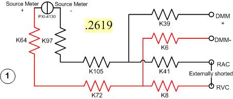
I have a problem with a PXI-2530 switch card work in matrix mode 4 X 32. I need to determine the resistance of the pairs of specific relay within the matrix. I have a PXI-4130 and a PXI-4071 in the same chassis, so I take measures 4-wire in a configuration like this...
Resistance symbols represent relays in the switch. Here is a representation of matrix-style switch routes I use. (This should look more like the interface of soft face before switch)
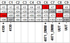
The two diagrams represent so how I take my measure. I shorted outwardly columns C8 & C9 (shown in the first graph), I am sourcing 500 microamps of current and toggling the current source for a positive and a negative measure, I am able the voltage with the DMM. For the above measure I'm mesure.2619 ohms. This should be of course my resistance of the relay K8, K41, as well as Terminal block and wiring.
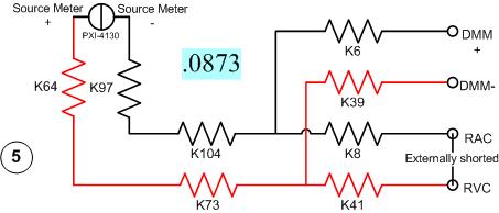
Here's another schema. This should measure the resistance of two same...
All I have changed is routing between the meter from the source. Here's the view from the matrix...
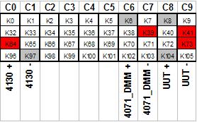
With this measure I'm mesure.0873 ohms. I can have the same resistance as the first example except getting a very different measure.
It gets even more interesting. If I had to take 4 pairs of wires, I use here, there are 16 possible configurations. I took each of these measures, and half of them gave me environ.25 ohms while the other half gave me environ.09 ohms. I tried this on a 2nd chassis and got the same result. My data are in the attached sheet. (My examples above are rows 1 & 5.)
Taking the measure of how we are, all these measures should be substantially the same. I have a current source constant, (I even tried a crimp in instead of the 4130 and got the same result.) and the meter is high impedance. If I had a pattern for the PXI-2530, I could do a little more analysis to know why I get various measures. Is there some diodes clamp on the lines or columns in the matrix? Something external must act solange this circuit. If I can find out what that is, I could determine my resistance to relay to a quantifiable level of uncertainty.
Any help would be greatly appreciated.
Greg
It seems that I can't remove. The correct message was placed here...
Once again, my apologies for the incorrect positioning of the post.
-
PXI-6250 and BNC-2110 to 5V relay?
I try to use the PXI-6250 by BNC-2110 relay 5V. Please advise if this is possible and how.
Thank you
Liming
Hello liming,
It is certainly possible, but there are some limitations. Are there current requirements for the 5V relay. If it is low current, you should have no problem controlling the relay with one of your PFI lines (they are located in the Terminal screw of the BNC-2110).

-
Hello
I have a module SH200LFH-4xDB50F-S cable and NI PXI-2575.
Switch Soft Front Panel, under the schematic tab and 1 wire 196 x 1 topology, when I log in, say, channel 189 and COM and check the electrical contact between terminals 22 and 23 of the 50 pin-connector P4 SUB D, I get the contact. Fine.
But when I choose the topology of 95 x 1 2-wire, I think that if I close the relay k0 e.g., she closed the circuit between CH0 and CH95, both between pins 1 and 2 of the 50 connector pin. But this does not happen.
EDIT: Another way I thought that it worked if I for example close the k94 relay, I would contact between the positive cable of k94 and COM + (and k94 - with COM-) but that doesn't seem to be the case either.
Am I wrong?
Thank you
LFH200 Cable Installation Instructions: http://www.ni.com/pdf/manuals/373848f.pdf
NEITHER SMU/PXI-2575 Specifications: http://www.ni.com/pdf/manuals/373870n.pdf
Baobob,
I think you can close the wrong relay. Channel 94 is actually closed by driving relay k41. I would check the hardware diagram 2575 in aid of switches of OR for complete information on the person who closes the channel. I think it would be much easier to use the channel API to open / close the channels as the documentation of cable described the 'string' not the relay.
FYI, the reason for which the relay and the channel are different is that exchange channels depend on the topology and the relays are static for the whole device regardless of topology.

Maybe you are looking for
-
Cannot retrieve/reinstall Mac OS Yosemite (No. HD/Locked)
Hello Before I tried to reinstall Mac OS X Yosemite I erased my Macintosh HD first, but I got an error that I don't remember, after that it's what shows when I click my disk utility on Macintosh HD. Then I went to pick up my laptop so I can use it ag
-
{Cannot acess Photos in iCloud - "Internal Server Error", "error code": 500}
Hello. I've always used Photos app inside icloud, but since 2 weeks ago, I just cant. Whenever I try to use photos inside icloud.com app I got the same error ("Internal Server Error", "error code" {: 500}.) I can still see my photos get updated throu
-
T420s: search for BIOS with Whitelist WAN card
Hey people, Depending on the subject, is there anyone with a bios works? I would use the Ericsson F3507 WAN adapter, but with original BIOS Lenovo, I get "Error 1802" during the pre boot screen. I already tested a modified Bios of Camilo (http://www.
-
Security update KB2378111 install not on my Windows Vista Home Edition 64-bit SP1 system! Help!
Every other security update installs normally with the exception of KB2378111. I get an error code 80073712. What should I do? Windows Vista Edition 64-bit SP1 family
-
Impossible to install iTunes on my PC
I tried to install iTunes on my PC (windows 7, 64 bit), but there is an error message below. I contacted Apple support, we discovered that there is a progeram called "apple software update" cannot be installed. Someone knows how to fix this? Thank yo