Question of sampling DAQ Assistant
Hi all
I have attached a VI that I used to record data from a few different voltage and the channels of the strain. All channels and sensors work perfectly and the VI reads data very well, but will be only newspaper for about 9 seconds. I found that the reason is that, within that period, the amount of updated read samples is reached. I also found that the reason for which is rather than on the statement sampling DAQ assistant 50 or 100 Hz it samples at a rate of about 1.6 kHz (0,000620 seconds). I have nothing seems to change the rate of that sample to so if anyone has any ideas it would be much appreciated!
Thank you very much
Andrew
I think I can explain what is happening. In a previous post, the op mentions using a 9237. That has a sampling rate minimum of 1.63 kech. / s. The rate in the corresponding file.
Andrew,
Read the Manual would have answered your question.
Tags: NI Software
Similar Questions
-
I was wondering, if I put the DAQ for continuous sampling and fixing the rate of say 1 kHz, then I read a single sample DBL value in a loop, what I'm reading in this sample? What is an average of the sample data acquisition carried out at the rate fixed? I am trying to monitor analog voltages on 9 channels. What is the point of a rate of sampling on data acquisition, if I read just a single sample?
Should I put it "N n samples" take advatage of this setting that has been done on the data acquisition hardware? See the screenshot of the code below. Thank you.
Transpose the data in the spreadsheet VI write. There is a Boolean input to the function that does this.
Best regards
-
Units of the number of samples and rates for the DAQ Assistant units
Hello
I use the DAQ assistant for analog voltage of an input OR data acquisition card. What is the difference between the rate and the number of samples in the DAQ assistant and what are the units of the two?
Thank you.
The number of samples is how many discrete to measures. Rate (per second) is how fast to acquire the specified number of samples.
If number of samples is 100 and the rate is 1000 samples per second, then the acquisition would take 0.1 second (100 / 1000).
-AK2DM
-
Meilhaus 3106 MAX/DAQ Assistant questions
Hello
While I'm sure that you all have grown tired of my usual throat-clearing, I'm a relatively inexperienced developer, so apologies in advance if this question is incomplete or missing otherwise.
I recently got a Meilhaus electronic RedLab 3106 DAQ. Box manual is at: http://www.meilhaus.org/downloadserver/redlab/manual/RedLab%203106_en.pdf
Attempt to use this device after completing installation 'Quick Start', I discovered that the data acquisition was not read by MAX (v5.0). In addition, by attempting to use the DAQ Assistant, in LabVIEW 2011 for this box DAQ (which I did successfully on this machine with a DAQ USB of NOR-6008), I discovered that the device is not listed with the text "no taken physical channel supported" that appears when the registration of the channel would be generally.
Normally, I try just a reinstall of the drivers/software 3106 package, but the strange thing is that Windows (XP - SP3) gives me the bubble 'New hardware found' when the USB fuelling the DAQ cable is connected to the computer. In addition, the acquisition of data can be read by a program that came with the acquisition of data called "InstaCal", including an order to make the power led on flashing box. Finally, a universal library, which also comes with the DAQ hardware has itself installed successfully in LabVIEW under "User Libraries". Given this feature, I am convinced that it is simply not possible to use the DAQ Assistant in LabVIEW for this particular data acquisition or that there is something in LabVIEW/MAX in need of fixing.
Someone knows a problem similar to this with the 3rd party hardware (ideally, Meilhaus) and software of NOR? If so, how do fix you it?
Kind regards
MG Wilkinson
Material acquisition of third-party data is not supposed to be detected by MAX or used with the DAQ Assistant. Thus, simply use the functions you provided.
-
DAQ Assistant: Reading of the samples that are no longer available
I'm trying to use the DAQ Assistant to read some data, but I get "error 200279 occurred at DAQmc Read (analog 1-d Wfm NChan NSamp) .vi:2.» The error message suggests to increase the size of the buffer, most frequently read data or by specifying a fixed number of samples to read instead of reading all the available samples. My sync settings are as follows: continuous samples for the Mode of Acquisition, 1 K samples to read, 1 K Sample Rate (Hz). I'm curious to know what would be the best settings for this. If I set the mode to 1 sample (on request), would simply take a sample each time the loop works? Help, please.
Thank you
Brian
Brian,
Please post on the Forums of NOR. Adnan a reason on why you get this error. If you use the sample on request, you will get only a value returned for each iteration of the loop. If you only need to try from time to time and there is no need to be very consistent, then this might work for your applications, but it depends on what type of application you have. How fast do you need taste?
-
Outbreak of DAQmx N-sample and the Acquisition using DAQ Assistant
Hello!
I'm still fairly new to LabVIEW and I am working on all the points of connection. I would like to acquire a finite number of samples of analog data from a CompactDAQ system when a Boolean event of internal software (like a button of VI). I followed the examples to implement the acquisition with the DAQ Assistant, which works very well. I don't understand how I can use a software trigger, but I don't see how hardware triggers are configured in the trigger tab in the DAQ Assistant.
I don't know that this should be very simple; Maybe I'm just ignorant of the configuration used for this sort of thing. Also, I could find soon I need to go beyond the DAQ Assistant for some of what I want to do, so any pointers to good references or tutorials on programming DAQmx are welcome.
Thank you!
Ryan
You can simply put the acquisition within a value of the Boolean control change event.
-
Control relay with Boolean switch using DAQ assistant 9481 - problems
Sorry for what may be a stupid question but I'm stuck in quicksand.
I use a relay module 9481 and have two external relays connected lines 0 and 1.
When I create a digital output 0 line by line, I can run the test inside the express and activate the relay and turn off without problem.
The generated block DAQ expressed expects a Boolean input of 1 d. (See attached photo).
I want to connect a Boolean switch relay line disk 0. You can connect live not because the switch is Boolean and the input is Boolean 1 d - I'm a conversation in the pict.
All plumbing lines display results, the relay never active.
Any bunch would be greatly appreciated! Thank you
Mr._Mechanical,
Welcome to the Forums of switch OR this forum is generally intended for products OR-SWITCH [such as the NI PXI-25xx & NI SCXI-11xx], I think I know the answer to your question.
I think the reason why it's a failure is the conversion you make generates a table of 16 Boolean [as the 'boolean to (0,1)' function creates a data I16 type] with your data more false data points 15.
When you try to control the relay, he sees 16 datapoints are you Commander to a single port [channel] and so error out.
My suggestion would be to use normal DAQmx digital output screw [with, he set up as ' Digital > single channel > single sample > Boolean (1 line) "] rather than the DAQ assistant.
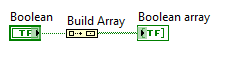
If you use the daq assistant, simply by using the function 'Building the table' will transform your simple Boolean data point in a Boolean array containing a single element.
While the DAQ assistant is very easy to use, I recommend that you use the DAQ assistant, because this reduces the features and increases the execution time.
-
DAQ Assistant does not export the values on the scale
Hello all-
Potentially stupid question but here goes: I'm using the DAQ Assistant to read in 4 analog input voltages, continuous sampling acquires data at 10 Hz 1 point, using LabView 12 on a machine with an acquisition of data USB-6341 simulated device (because my office is more comfortable than the lab!). I want to change the first two signals of voltage to temperature and humidity, respectively. I used the «create a new...» "in the 'Custom Scaling' drop-down in the"Voltage configuration"tab for each of these channels, named gave the slope and the intercept at the origin for the respective linear scales and click OK."
When I test the code - and yet once again, I'm not on a machine with a 'real' DAQ system, I use a simulated device, and it seems that NEITHER MAX generates a sine wave of long period with little noise on top for this - I do not get the results on the scale of my 'signal', I get the raw tension. (If you run my code, I will join, the Relative humidity must be between 0 and 100 and temperature-40 to 60, is not 0 to 5, for example.)
So, what happens? Is there some flag or setting that I missed? The scaling only works on voltage data 'real' of a 'real' instrument DAQ, instead of a simulation (which is why I mentioned twice!)? I have to do something in NI MAX as well as Labview?
Thanks for any help you can give.
John Easton
Simulations devices will not respond to custom scale. They are just supposed to allow you to configure your device without errors when you do not have the unit on-site.
"NOR-DAQmx simulated devices create a noisy sine wave to all the entered analog." Simulated data other set-up is not available at this time. »
http://www.NI.com/white-paper/3698/en
They generate a sine with an amplitude equal to half of your specified input range. If you want to work with simulated data that would be more realistic for your application, you could write a VI to generate the data and have a business structure to manage both "simulations" and "real", then you could switch back depending on whether you have access to the material.
I just checked this with a PCI-6254 I install and simulated a PCI-6254.
-
Simulate signals wired to the DAQ assistant for USB-6009 device
Hello
I'm trying to send a signal to the DAQ Assistant Express VI. I watched the movie "Generating a Signal" on the Web site of NOR (www.ni.com/academic/students/learnlabview/generate.htm) and I have my Signal simulate connected directly on the DAQ Assistant, as shown in this film. In my case, the DAQ Assistant sends the signal to a device USB-6009.
However, I received this message:
Error-200077 occurred to the DAQ Assistant
Possible reasons:Requested value is not supported for this property value. The value of the property may be invalid because it is in conflict with another property.
Property: SampTimingType
asked the value: Sample clock
You select: On-demandIf I select 'On Demand' in my DAQ assistant and run the vi everything works beautifully. However, I need my DAQ assistant to be configured to generate a waveform AC continuous, not output a single alternating current rippling.
What happens here? I did not have this problem before on other devices of NOR. I am using LABView 2010.
Please answer.
Thank you.
-
Multiple entries to the DAQ Assistant
Hello
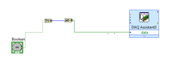
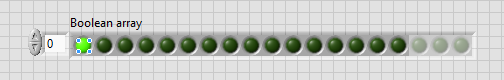
I'm doing my DAQ Assistant, in several (formed of an array) Boolean inputs where there is 1 digital output. (see attached software folder)
Physically, I want a valve to open and close at a certain pace, where the user can install/control this pattern until the program starts.
I think that the best way to do it is to have multiple Boolean values that the user can press or unpress.
Before that, I started, I tried with only Boolean 1 where it worked perfectly.
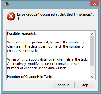
As seen on the attachment (error), it is possible to an easy problem to solve, but I just can't figure it out, I'm stuck at my already made solution.
I use USB6008.
I hope that there is a gentle soul who can help out me.
Best regards
Kenneth G. Vejen
Hi Kenneth.
When the output to the generation mode is set to "sample 1", which means that whenever you call the DAQ Assistant will generate 1 sample. In order to generate 5 samples, you must therefore call 5 times.
I have attached a modified version of your VI, which shows a way to archive it. However, be aware that the samples will be generated fast and not at 100 ms note your loop runs. It depends on your application, if it is as you want samples to be issued.
-
DAQ Assistant acquires the data into segments
I'm writing a code that reads and records the voltage, temperature and pressure on a cdaq-9174 using or 9221 and cards or 9173. The problem is that when the daq assistant is set to N samples outputs the data blocks in the graphics. I wish it were a continuous stream so I can see what is actually happening. I tried to change continuously, but it gets an error or is has data about 16000 points in 10 seconds, which is a lot more that I prefer. The code I am using is borrowed from another person and then the installation exactly it works on this computer, but not mine. Does anyone have any suggestions on how to solve this problem. I enclose the code as well as the sub live he uses.
Thanks for all the help. I didn't know at first that the NI 9237 card has a minimum sampling rate of ~ 1600 Hz. I am now able to taste to 2000 Hz then use decimating continues to write in my file at 200 Hz.
-
Second DAQ assistant in the power control system does not
Hi all
I need your help on this issue. I'm currently programming a VI for one command power supply for pool boiling experiments. The organizational structure of the VI program is attached.
I use two assistants DAQ for steady-state acquisition and temperature unstable state data respectively. The first assistant DAQ (samples to read 5, 5 Hz rate) for the acquisition of works unstable state data well (see the attached image file first DAQ Assistant for acquisition of temperature unstable state). The second assistant DAQ (samples to read 12 k, 200 rate) for stationary data acquisition does not work (please see attachment image Second Assistant DAQ of steady-state temperature acquisition), showing only a series of data files size of 1 KB with no data on the inside. And indicators for steady-state data also revealed nothing.
After a similar Q & A search in the forum, I tried to distribute different channels for 1 and DAQ assistant 2. However, the situation was almost the same.
The material I used are chassis SCXI 1000 and SCXI 1303 Council to acquire thermal couple temperature data. Food was AMREL SPS200-50-K025. LabVIEW software is the 2014 version.
I had just started to learn LabVIEW for only a month, and I know that the VI is a little messy. Hope you guys can also give me some advice on how to improve this VI.
Have you looked at the error on the second daq assistant? You will see that a reserved resource error because you cannot use two different assistants. You do not mention the real DAQ hardware but there a clock unique convert. You can use only one assistant with a unique sampling frequency.
-
When I try to convert my DAQ Assistant tasks with a right click - Convert to task NOR-DAQmx I get a name and a scrolly input output with all the broken wires. Similarly, if I create a task in MAX and then use a constant for the task on the block diagram name I get the same result of entry scrolly. Am I missing a step here?
Thank you
Hi Mirabelle
Glad to hear that you managed to solve the problem! In response to your questions:
-L'information that read you about the creation of tasks in MAX is correct; It is possible to create a global task (an available screw a lot) in MAX. However, it is not necessary to create all of the tasks in MAX. As you think, if you use the task within a single VI, there is no need to create the task in MAX - in fact, it's probably easier just to create the task in the VI himself, either with screws of Express Assistant DAQ or DAQmx screw person on the range of functions located under e/s measurement > DAQmx - Data Acquisition.
-When tasks change in MAX, it will not automatically be changed in LabVIEW. To make changes in LabVIEW, you will need to edit the task properties in LabVIEW, or remove the old task and replace it with the change.
-I'm not sure what you mean by the question in your "P.S." to 100%, but I'll try my best to answer. Is there a specific example you speak? If you ask the use of screws DAQmx as DAQmx Virtual Channel Create, task control DAQmx and DAQmx Read etc., as shown in the examples of the expedition, then there are a few reasons to use those. Basically, screws of Express DAQ Assistant consist of a combination of the screw in the DAQmx - Acquisition of data from the function palette section. In general, screws of Express DAQ Assistant moving slower than the standard SIE DAQmx. It may be easier to debug the code when using standard screw, as it is obvious which task runs each section of the code. And finally, there are some limitations to the use of the DAQ Assistant, so while they may be easier to use in the short term, long term, I would recommend familiarize themselves with standard screws, because they make possible more complex tasks.
I hope this helps! Feel free to let me know if you want to bring me anything, or if you have anything else that I can help you.
Best regards
-
How can I programmatically change the parameters of voltage range in a DAQ Assistant
Hello
First post here.
I need to be able to change the properties of voltage range of a daqmx assistant DAQ based on user input. My material, an SCXI module - 1102C does not change this property on a running task, so I would together the range of input voltage analog before activating the DAQ Assistant, or break the DAQ Assistant immediately after it starts, set the values, and then resume.
I don't know how to change the task ahead because the DAQ assistant creates the task when it is running, and there is no job before that.
In the attached photo, I have a conditional section, configured to run only if the loop iteration is 0. I take the task of the Daq assistant, sending him stop vi of task, set the property and then send the task with the snap the vi task. I can watch him run with lightweight debugging on, and everything seems to work properly, but on the second (and all others) iteration of the loop, I read I. Max and it seems that a re DAQ Assistant set it to the 5V. You can see what's going wrong here?
BTW, there is a continuous acquisition and the code doesn't produce error messages when executing.
I've encountered a similar question someone posted here in 2006, but his question was specifically a Labview API (VB, I think) and not a real solution of G.
Attached are the real vi in question and a PNG of the block diagram.
Thank you!
Ruby K
First of all, if you want to start getting beyond the basics with the DAQ hardware, you have to stop using the DAQ assistant and do it with lower level VI DAQmx. There are hundreds of examples in the finder of the example. You can even make a right-click on the DAQ assistant and select open front panel. This will create a Subvi, you can open and see what is happening behind the scenes. Do it. I think you will find that the task DAQ is recreated on each (although I'm not 100 percent the way parameters are established or maintained in each section of this sub - VI).
The second problem is that you have a bit of a race on iteration 0 condition. These two property DAQ nodes are running at the same time. Thus, when you read the AI. Max, this can happen before or after the AI. Max is located in the structure of your business.
Thirdly, make sure that involve you your son of the error.
-
Hi all
This should be a pretty simple question, but I can't seem to find the answer online and currently do not have the functionality to test this:
I'm using LabVIEW 8.5 and have a VI that imports data from sensor through the DAQ Assistant. In the configuration tab, there is a range of signal input. What happens if my sensor exceeds this range? I get a warning? The default value is the maximum (or minimum)? I was interested in writing a code to display an error that I approach the limits of this range, but did not know if I also need to include code to display an error if the scope is exceeded as well.
Thanks for the help,
Tristan
Hello, Tristan,.
The behavior depends on the selected range and the device you are using.
If you are using a device with a single input range is valid, we will use this range, even if you set a smaller minimum and maximum in the DAQ Assistant. So, if your device only supports ±10V and you set the range to ±8V, you will still continue to get valid data after your top sensor 8V until what you approach 10V. When you reach the limit of the extent of your device, the output will be 'rail', and simply return the maximum value until the signal is less than the maximum value again.
Note: A device that is nominally ±10V usually has a go-around (such as ±10.2V) which are usually specced in the manual.
However, if you use a device with several ranges of entry then things become more complex.
NOR-DAQmx player will choose the smallest range that entirely covers the interval you choose. For example, suppose that your device supports the following input range: ±0.2V, ±1, ±5V, ±10V and you choose 0V - 3V as the range in the DAQ assistant. The NOR-DAQmx driver will focus on the input range and the list of the entry lines that your hardware supports and choose the smallest encompassing the entire range that you set. This would be the ±5V, because this is the only beach that contains up to 3V. Thus, all between ±5V input signal is returned and none outside this range will be 'rail' to the maximum or minimum value.
We do this because using small beaches make more efficient use of the resolution of the ADC. So, we try to use the most effective range based on what you ask without picking up a range that will make you miss data.
Let me know if I can clarify it more.
Maybe you are looking for
-
Minor graphical change axis scale markers to multiples of 6
I have a chart whose axis go from 0 to 36. For some reason any when I choose the uniform spacing marker, I get markers at 0, 5, 10, 15, 20, 25, 30, 35 and 36. It is, incidentally, NOT uniforms marker spacing. Uniform spacing would be equal increme
-
The webcam on my x 301 refuses to work. Whenever I try to use it, there is no green light, and when a screenshot is taken, it appears all black. The work of micro / audio, but not the camera. I did everything I could to make it work, but nothing has
-
my laptop starts up then the screen goes black and says no operating system found
My child put their hands on my laptop now it starts and then it says no operating system found, or there is another sign that comes up it says Security Accounts Manager intiliaztionfailed because of the following error: the handle is invalid. Error s
-
at the start of my computer: these two windows appear indicating "InCD cannot start.
-
Deskjet 3521 alignment problem
I created my 352. It works & fine print from my Mac and iPad. But after several hours of non-use, it will allow the auto shut-off even though I have this feature in "off" position. When I turn on the printer, I'm prompted to print the alignment page