Conversion task DAQ Assistant
When I try to convert my DAQ Assistant tasks with a right click - Convert to task NOR-DAQmx I get a name and a scrolly input output with all the broken wires. Similarly, if I create a task in MAX and then use a constant for the task on the block diagram name I get the same result of entry scrolly. Am I missing a step here?
Thank you
Hi Mirabelle
Glad to hear that you managed to solve the problem! In response to your questions:
-L'information that read you about the creation of tasks in MAX is correct; It is possible to create a global task (an available screw a lot) in MAX. However, it is not necessary to create all of the tasks in MAX. As you think, if you use the task within a single VI, there is no need to create the task in MAX - in fact, it's probably easier just to create the task in the VI himself, either with screws of Express Assistant DAQ or DAQmx screw person on the range of functions located under e/s measurement > DAQmx - Data Acquisition.
-When tasks change in MAX, it will not automatically be changed in LabVIEW. To make changes in LabVIEW, you will need to edit the task properties in LabVIEW, or remove the old task and replace it with the change.
-I'm not sure what you mean by the question in your "P.S." to 100%, but I'll try my best to answer. Is there a specific example you speak? If you ask the use of screws DAQmx as DAQmx Virtual Channel Create, task control DAQmx and DAQmx Read etc., as shown in the examples of the expedition, then there are a few reasons to use those. Basically, screws of Express DAQ Assistant consist of a combination of the screw in the DAQmx - Acquisition of data from the function palette section. In general, screws of Express DAQ Assistant moving slower than the standard SIE DAQmx. It may be easier to debug the code when using standard screw, as it is obvious which task runs each section of the code. And finally, there are some limitations to the use of the DAQ Assistant, so while they may be easier to use in the short term, long term, I would recommend familiarize themselves with standard screws, because they make possible more complex tasks.
I hope this helps! Feel free to let me know if you want to bring me anything, or if you have anything else that I can help you.
Best regards
Tags: NI Software
Similar Questions
-
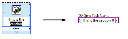
Task of naming of the DAQ Assistant
I not bad by using DAQ Assistant to create a task to do what I want, but I can't understand how to give a meaningful name to the task. The name of the task seems to be assigned arbitrarily to something like "Assistant_1 DAQ", which is not very useful for me.
Please advise on how, in the "convert to NOR-DAQmxTask", procedure I can assign a different name to the task. If not, is it possible to rename an existing task?
Hi wildcatherder,
There is already a way to set the name of the task in the present case, but it is not quite obvious and has a little whim. If you change the legend of VI DAQ Assistant express before selecting "Convert to the NOR-DAQmx task", he uses the legend that you specified as the name of the task in Max... and then he adds "_0" at the end:
If you have a suggestion to improve this feature, perhaps you could post it to the Exchange of ideas, information Acquisition?
Brad
-
How to create a task in the DAQ Assistant of LabView for one of our modules cDAQ without actually being connected to the cDAQ module?
You can simulate a large number of instrument supported by DAQmx with Measurement & Automation Explorer.
Right-click on the NOR-DAQmx devices and then create new, then simulate and choose from the list of supported devices.
For the cDAQ chassis first then your module.
Excuse me, but I don't have an English version of MAX and so I did not have the correct translation of command...
When your simulated device is configured, ca use you it with the DAQ Assistant in LabVIEW.
-
Control relay with Boolean switch using DAQ assistant 9481 - problems
Sorry for what may be a stupid question but I'm stuck in quicksand.
I use a relay module 9481 and have two external relays connected lines 0 and 1.
When I create a digital output 0 line by line, I can run the test inside the express and activate the relay and turn off without problem.
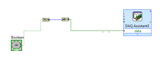
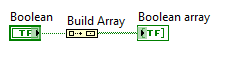
The generated block DAQ expressed expects a Boolean input of 1 d. (See attached photo).
I want to connect a Boolean switch relay line disk 0. You can connect live not because the switch is Boolean and the input is Boolean 1 d - I'm a conversation in the pict.
All plumbing lines display results, the relay never active.
Any bunch would be greatly appreciated! Thank you
Mr._Mechanical,
Welcome to the Forums of switch OR this forum is generally intended for products OR-SWITCH [such as the NI PXI-25xx & NI SCXI-11xx], I think I know the answer to your question.
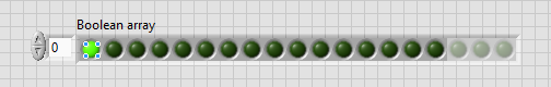
I think the reason why it's a failure is the conversion you make generates a table of 16 Boolean [as the 'boolean to (0,1)' function creates a data I16 type] with your data more false data points 15.
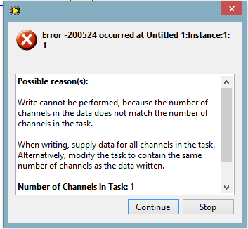
When you try to control the relay, he sees 16 datapoints are you Commander to a single port [channel] and so error out.
My suggestion would be to use normal DAQmx digital output screw [with, he set up as ' Digital > single channel > single sample > Boolean (1 line) "] rather than the DAQ assistant.
If you use the daq assistant, simply by using the function 'Building the table' will transform your simple Boolean data point in a Boolean array containing a single element.
While the DAQ assistant is very easy to use, I recommend that you use the DAQ assistant, because this reduces the features and increases the execution time.
-
Under VI 'DAQ Assistant': Sub VI is not executable
Salvation OR engineer,
My task is to acquire and record data of input voltage analog with PCI-MIO-16-1 and BNC-2110 connector. I can get the signal via MAX, but as soon as I drop down the function palette DAQ assistant in FASHION Lab blocks diagram, my run button becomes broken. I got the error message like "Sub VI"DAQ Assistant": Sub VI is not executable. How can I overcome this?
Thank you
Yvette.
Hi Paul,.
Unfortunately, SignalExpress is a different license than LabVIEW. However, you don't need a SignalExpress to acquire and record data. LabVIEW has every ability to SignalExpress and many more.
Kind regards
-
I've just updated LV 2009 SP1 LV 2010. I use a LV 32-bit on a 64-bit computer.
When I open the DAQ Assistant, I get a pop up window that says "LabVIEW: an exception occurred in the external code that is called by a function of the call library node." This could have corrupted memory of LabVIEW. Save all work to a new location and restart LabVIEW. VI "Advanced Timing.vi:1" was arrested in node "" a call to "get of DAQmxAssitant_DAQmx IO Info.vi of control.
If I hit OK, DAQ Assistant is locked up, if I use the Task Manager to close the LabVIEW vi breaks down.
I already reinstalled 9.5.1 DAQ device drive. without success.
There is no such version. The most recent is 9.2.2.
-
Cannot get DAQ Assistant in Labview to cDAQ 9184
I am trying to build a system for the acquisition of data with one NOR cDAQ 9184. I installed the drivers for the system and I'm able to get to the DAQ system using NI Max (under my system - devices and Interfaces - devices on network) and all channels appear well, however, I tried to follow the procedure described in http://www.ni.com/white-paper/11703/en/#toc2 to integrate my system with LabView and I am unable to find the tab software under the unit to be able to write the RIO 3.5.1 on the appliance and cannot find the device to through the LabView project.
Your real problem is error-50103. This is a common mistake, and you can find the answers for it if you are looking for in the forums.
The problem is that you can't have several tasks (or several assistants DAQ) try to access the same device at the same time.
Make a DAQ assistant who has all defined channels you wish to purchase.
-
How can I programmatically change the parameters of voltage range in a DAQ Assistant
Hello
First post here.
I need to be able to change the properties of voltage range of a daqmx assistant DAQ based on user input. My material, an SCXI module - 1102C does not change this property on a running task, so I would together the range of input voltage analog before activating the DAQ Assistant, or break the DAQ Assistant immediately after it starts, set the values, and then resume.
I don't know how to change the task ahead because the DAQ assistant creates the task when it is running, and there is no job before that.
In the attached photo, I have a conditional section, configured to run only if the loop iteration is 0. I take the task of the Daq assistant, sending him stop vi of task, set the property and then send the task with the snap the vi task. I can watch him run with lightweight debugging on, and everything seems to work properly, but on the second (and all others) iteration of the loop, I read I. Max and it seems that a re DAQ Assistant set it to the 5V. You can see what's going wrong here?
BTW, there is a continuous acquisition and the code doesn't produce error messages when executing.
I've encountered a similar question someone posted here in 2006, but his question was specifically a Labview API (VB, I think) and not a real solution of G.
Attached are the real vi in question and a PNG of the block diagram.
Thank you!
Ruby K
First of all, if you want to start getting beyond the basics with the DAQ hardware, you have to stop using the DAQ assistant and do it with lower level VI DAQmx. There are hundreds of examples in the finder of the example. You can even make a right-click on the DAQ assistant and select open front panel. This will create a Subvi, you can open and see what is happening behind the scenes. Do it. I think you will find that the task DAQ is recreated on each (although I'm not 100 percent the way parameters are established or maintained in each section of this sub - VI).
The second problem is that you have a bit of a race on iteration 0 condition. These two property DAQ nodes are running at the same time. Thus, when you read the AI. Max, this can happen before or after the AI. Max is located in the structure of your business.
Thirdly, make sure that involve you your son of the error.
-
What is the benefits of the acquisition of data from the block DAQmx rather than using the DAQ assistant block? Are there pro on and con everyone? What is normally used in the industry?
I also noticed there are several methods to write data to file and I was wondering what are the right method or the pros and cons for this?
Dawud-Beale wrote:
What is the benefits of the acquisition of data from the block DAQmx rather than using the DAQ assistant block? Are there pro on and con everyone? What is normally used in the industry?
You have MUCH more control on the acquisition with the DAQmx API on the DAQ Assistant. You can also make the code more efficient with the API. Normal in the industry to avoid the DAQ Assistant
The only real advantage of the DAQ Assistant, it is easier to set up your task.
Dawud-Beale wrote:
I also noticed there are several methods to write data to file and I was wondering what are the right method or the pros and cons for this?
Well, that all depends on your needs.
Need human readable? Go with a CSV or tab delimited text file.
You will need to register a lot of data quickly? Use a binary file or a PDM. I tend to use the PDM because it is well set up for the acquisition of data and waveforms.
-
Precise triggering voltage input and output generation in the DAQ Assistant
Hello
I wonder if anyone has come across a simular problem with the synchronization of input and output voltage. I use a box 11 LabView and NI USB-6259. I have been using the DAQ Assistant to configure the input and output channel. In particular, my task is to generate a single rectangular "pulse" as the output voltage to drive a coil and once the pulse went to get a signal from a sensor of magnetic field and get a power spectrum. This means that the order and the time during which the DAQ Assistant is used is extremely important. For example, the output voltage channel must be opened first for 2 seconds. Subsequently, the channel of input voltage must be open for 1 second, in which the sensor signal is obtained and post-processed. Only after these tasks are performed in this order he can can be repeated in a loop until the experiment is over. I don't know how to trigger data acquisition assistants (one for entry) and the other for the voltage output correctly. Y at - it a trick?
See you soon
Michael
Hi Dave,.
Thank you that I wired the error strings but the timing issue was unrelated to it. In the DAQ assistant, I simply had to choose the continuous aquistion of the 'samples' methods 'N-switch' for input and output voltage and all works fine now.
Thanks again
Michael
-
Nor given DAQ Assistant District recognize a USB chassis and modules, but does "Measure."... »
I use Labview 2012 full development and a chassis 8 slots cDAQ-9188 with nor-9203 (current), OR-8205 (voltage), OR-9213 (thermocouples) and NOR-9485 modules (switch) are installed. Measurement and Automation Explorer, network devices, recognizes the chassis and modules installed, evidenced by the serial numbers of each poster. I downloaded DAQmx 9.6.1. District data nor DAQ Assistant acknowledges that the chassis or modules. So far, I don't think I'm confused, but I am.
Thanks, Marand. As I wrote in the post, MAX recognized 9188 Chassis network devices and modules installed in the right-a panel cites. District data nor Assistant recognized DAQ chassis or modules. The solution was incredibly simple, but subtle. CompactDAQ chassis and modules connected to the computer via the USB port are automatically recognized, and it is what I expected. However, the 9188 is an Ethernet chassis; While the chassis has been recognized on 'Network', I had to choose "Add Device" to have MAX recognize modules. Just by clicking on this option filled the tree. All is well now. I must tell you the steps you suggested are exactly those suggested by an engineer from disks OR I've met. It was during this conversation that I proposed by selecting "Add Device" just because we had tried everything else. Thanks again for your help...
-
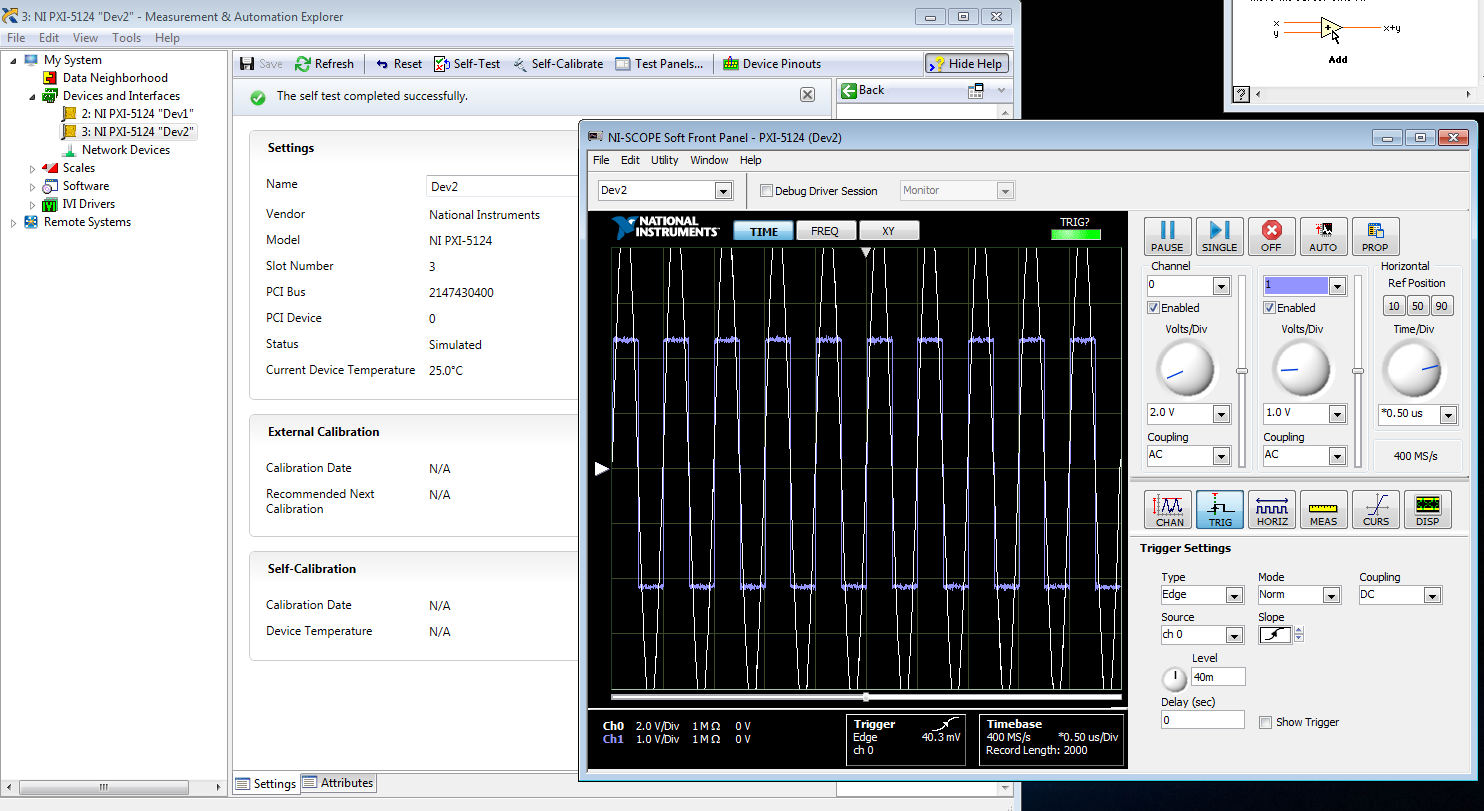
I am trying to create a development machine, where we can test the new code without using our physical hardware. I followed this guide to set up a system of simulation. I get to step 3.2 b, but the device does not appear in the DAQ assistant. MAX, the device self test and gites calibrated successfully, and when I open the test panels, I see some sort of signal. I guess that's a default entry simulated since I didn't that device to look for anything? Note that two devices, I am creating the show upward into the devices section and Interfaces, but that, even after running auto calibrate, automatic Calibration date is not yet specified.
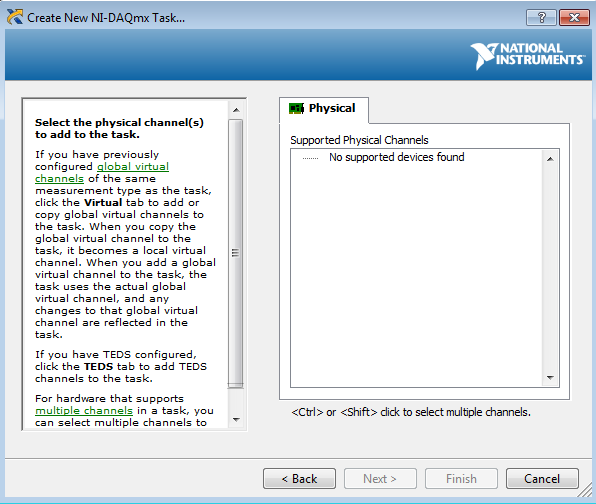
When I try to test the device and create a voltage according to the guide, I can't see a device in the creator of data acquisition task.
Steps 1 and 2 of this guide are of course met. Step 3 is not, but this is not surprising because a simulated device is in device in any case manager. Also, I'm not under RT, so step 4 is satisfied.
Someone at - it ideas?
That would be because the PXI-5124 is a digitizer not an analog input device. You must use the NI SCOPE not NOR DAQmx driver
-
Consecutive calls to DAQ assistant
Hello
I'm working on something that is very probably simple. Maybe the problems stem from a bad initial design choice. The VI (and subVIs) are used at a voltage output, read another tension and react accordingly.
First the error I get is "error-200547.
Here's how the program works:
1 MOVR.vi
This generates two analog output signals, controlled by the same signal generator. There is also a digital signal, but I don't think that's the problem.
2 MTUL.vi (and MDTL.vi)
These use MOVR and read another voltage. Essentially, the voltage must be created until the limit is reached, and he decides to stop.
These two work as expected on their own.
3 IsoMeasure.vi
This is where the problems occur. Basically, this VI take MTUL and MDTL and makes a loop in a loop for, change the frequency of each increment. The observed performance is MDTL will work and try to start MTUL. It's when 'Error-200547' is thrown. The error code appears to be understandable, but "autostart" isn't clear for me using the wizard.
I would avoid using all daqMX code, but I will if I have to. If that's the suggestion, a good example is that sort would be great. If I can put the autostart Assistant, I guess it would help as well.
Thanks for all the tracks. I think it should work.
Hi drevniok,.
The reason why you get this error is that you try to restart your DAQ Assistant several times in your application. One important thing to note is that a task DAQmx configured and started only once each time the DAQ Assistant is called for the first time. Therefore, since you are stop and start the DAQ Assistant, in your application, the second time you call the wizard, it does not start the task. This is made more so by the fact that the function of writing in the DAQ Assistant DAQmx has his automatic starting of entry set to False.
Using the DAQ Assistant for Analog Output returns an error-200547
That being said, the DAQ Assistant is mainly used as a quick and easy to set up and use your DAQ hardware, however, it is a bit limited in functionality compared to the lower levels DAQmx live. This is a case that illustrates this limitation and therefore, I believe that the best solution this problem would be to use the DAQmx LabVIEW vis a lot shipping examples that can help you get started developing your application. These lie in you NEITHER example Finder under the menu help. "" The example I want to show you is the Regeneration.vi Clk - no Cont Gen Wfm - Int voltage under input and output material"DAQmx" analog generation "voltage.
Is another resource, I want to tell you the getting started with NO-DAQmx: Homepage, which are a collection of tutorials online on DAQmx programming.
I hope this helps.
-
several channels in daq assistant
Hi guys,.
My first post on this forum, would appreciate some advice.
I use labview 8.2 with PCI-6071E acq. card.
I'm observing unexpected behavior when you try to read analog data on my card.
If I define in the daq assistant, one way to read, everything is great, and the data is ready, as planned. I can see it in the preview window (explicit task)
When I open the daq assistant.
But, at the point where I have to add a channel more (from the same physical pci-6071e card), my measurements are totally fake - I get a strange signal...
The sampling rate is more than enough (I enjoy with 64khz a 1 kHz signal arriving at one of my channels).
What I'm missing here?
Thanks for any advice you may have.
Lenny
With the generator of signals (output TTL) or the PCI-6071E AO the gsignla is NOT differentiated. Use one of the configurations of single entry completed.
The Earth all unused inputs.
Lynn
-
Using DAQ Assistant with a system remotely
I'm new to LabVIEW and National Instruments hardware and I am trying to use an instrument with LabVIEW using the DAQ Assistant. I use a PC with Windows Vista and I am connected via a network to a PXI-8108 controller in a PXI-1050 chasiss chassis. The instrument is just a thermocouple which I use to become familiar with everything. The thermocouple is connected and the connection SCB-68 block which is connected to a PXI-6221 multifunction data acquisition in the chassis. I am able to create a task in MAX under remote system and everything seems to work. What I want to do is to use this instrument in LabVIEW, and it seems that for this I need to use the DAQ Assistant, but when I do it says no supported device is found. I wonder if there is a way to get LabVIEW lean on the remote system to see the acquisition of data and the thermocouple.
All advice is appreciated.
Thank you
Hi all
Ben is correct. RDA is no longer supported in DAQmx. We have another way to use DAQmx with a remote system. It is use DAQmx with an OPC server or simply by shared network variables. There is a section of the base of knowledge here that should help you get started. You should also take a look at the developer section area here. The basic idea is that you can use a variable shared within labVIEW that is bound to a variable shared on your networked machine. In this way, you can write and read values from a task DAQmx. Look at the instructions in the above two items and let me know if you have any questions.
Kind regards
Paul C.
Maybe you are looking for
-
macOS Sierra - Mail subject line empty on the answer
In the latest iteration of the mail under macOS Sierra, on you reply to a message in the subject line is empty. This happens only with Microsoft Exchange accounts and does not happen with my gmail account.
-
Solutions on device USB of Airport Extreme
Spending some time trying to connect a key USB of Airport extreme and to map it to a Mac laptop computer windows 7-computer windows 10. My solution after a bit of frustration: Fixed the problem of Player connection by downloading the Airport utility
-
the first tab open in firefox continuously charges and cannot be closed
When I open Firefox the first tab, I opened will be constantly and that it cannot be closed
-
Impossible to install the Safari 9.0.3 update
Hi all I have a MacBook Air (11 inch, mid-2013) with Yosemite 10.10.5. Latest version of Safari installed is version 9.0.1. When I opened the app store, it shows an update for Safari 9.0.3. When I click on update, it downloads the update, then instal
-
I do not have my camera connected to the computer. The original library was on an external hard drive thinking that maybe that's the question I consolidate the library and then put on my desk. Opening of the library on the desktop, no files are offli