Reactive power meter in Multisim
Hello, is there a way to create a phase three reactive power meter using the components/instruments in Multisim v12?
Thanks in advance!
Hi Tobster
(1) Yes... Conexion Aron is the same thing with 2 wattmeter method.
(2) the connection is good. But the formula is Q = sqrt (3) (XWM2-XWM3)
(XWM2 + XWM3) =P
SQRT (3) (XWM2-XWM3) = Q
S = P + JQ
ATT:
Alvaro Tasco
Tags: NI Software
Similar Questions
-
Power Meter Modbus rs485 via 9871
Hello
I'm under Labview 2015
I'm currently trying to connect has the place D Pm820 (meter) NI 9871 module in a crio 9076. The project is supposed to read the performance data in the registers of the meter (current, voltage, etc.) using the port rs485 on the back of the meter.
The pm820 has a pinout for rs485 2-wire with 1 (-) 2 (+) and a 3rd Armor/ground wire. The pm820 meter is a slave device that has several different protocols that it can run on (Modbus RTU/ACII8/7 and JBUS).
The setting of the counter are:
Protocol: Modbus RTU
Address: 1
Baud rate: 9600
Parity: None
I use the module 9871 for device communication for the cRio
I use the power cord that came with the module 9871 RJ50 to db9 and have the pins 4 and 8 rider (TXD + TXD +), and then connected to the (+) 5 and 9 meter jumper pins (-RXD, TXD) - and then wired to the (-) meter and ground on pin 1. I have read, it's how wire you the db9 connection rs485 2-wire.
My first goal is just to get the communication with the power meter so that the value that I see in the registry, it is what I should see.
I started using an example VI for holding registers (master modbus on target RT) reading as labview was pre-constructed and changed it so that its contribution would be to port 1 on the 9871 as created controls for my run configuration. Other I left the rest of the VI that it has been opened.
When I run the VI I see numbers appear in the registry list, but they have nothing to do with the power meter. I unplugged the power meter and still got the same result however if you unplug the cable connection the 9871 1 VI will be a mistake (as expected). I have the feeling that the labview speaks to itself through the 9871, but I'm not sure. I looked at other posts, trying to find a solution and came across a mention of having to set the thread mode, but I can't find a way to do it using the modbus library. However I could not find an example reading VISA registers the using visa I see there is a way to do it.
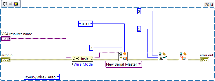
I enclose a picture of my VI and the front panel to show what I mean.
If I could help either make my VI work or at least get pointed in the right direction that would be great. I'm not against the use of the Visa library either. Also if you have examples or resources that would allow that they would be greatly appreciated
It's just a part of my project but just get work communication is my main priority at the moment.
Thanks in advance,
Mike
-
Hello
I have a power meter which provide the USB driver and a Labview program to get the data and NI USB-6221. The project I am currently working on the needs of:
1 acquire two signals (inputs of simple tension), pressure frequency KHz
2. acquire a flow signal, the output signal is 0 to 5V pulse, each pulse means 0.4 ml volume. So I use a voltage inflows to count impulses in certain period of time (in this case, 1 S) for water flow. ; KHz sampling frequency and the 1 Hz update rate
3. acquire a signal of engine speed. The output signal is pulse square wave whose frequency is related to the speed. I use a REIT port to measure the frequency. Sampling rate: Auto
4 give output voltage sine or square wave, I use AO do that.output rate: Auto
5 acquiring by VISA electricity meter data. Data update rate: every 50ms
Currently, all the 5 tasks work well separately. But when I put them together, some signals are beginning to hang, for example, pressure signals sometimes give nothing.
Another problem is the data record. I programmed the VI in such a way that whenever I press the button 'save start', he begins to record data and save them in a .cvs file. For some reason, I always get only the data in the first table. Coult someone help me? I download my code as follows
Hello
What I meant by open, write, close. For any type of file you are using.
Open the file, which produces a reference, then put the mention in a registry to offset.
Write data, using the function write (for this type of file) and the reference.
When you are finished, close the file reference.
Writing in the spreadsheet opens, written, close all at once. It is very good for this type of application.
***
The issue of the loop is more general. I would like to say first of all, I want to say that since each loop works on its own, it is own VI, and that this program has put all this into a single VI, which has a method to solve the problem is to disable all the loops and allow them one at a time to see if there is a culprit responsible for.
Using multiple loops executes the code at the same time, and some loops would be cycle faster than others, especially if some of them are loops just as they are.
Communication between the loops is a test to the address if necessary.
Running all these signals through different loops DAQ must also be examined. Don't know what questions are for read and write somewhat randomly in the channels.
-
How can I get the digital power meter?
How can I get the digital power meter?
I use a method similar to the example below to measure the market factor using the inputs of a multifunction data acquisition meter. If the duty cycle is 0% or 100% for a given period, DAQ reading times out and returns an error. In this case, I would get the digital state of the counter of entry so I can put as cycle to 0% or 100%. I want to do it without knowing the digital port and line the entrance of counter... for example I would like to continue referencing DAQ/ctrX since I already have this information.
The application uses an M series: PXI-6229 DAQ and LabVIEW 2011 to make a system customized for VeriStand.
https://decibel.NI.com/content/docs/doc-12396
For the moment I wired the block diagram to add a case structure to check the meter ID and string constants to set the identifier of digital input, as they share the physical connection. As much as I can say that makes the specific code for the PXI-6229 (or any DAQ with only two counters that share connections with p2.1 and p) 1.4
I have attached the VI sub.
When the device is used with a different data acquisition, I can add the connection and/or separate control. Looks like at least one will be necessary given that the meter can only detect the edges... I think it was the piece of information I needed.
Thanks for your help!
-
Read power meter in LabVIEW via RS-232/RS-485
Hello!
I have a power meter, an advanced WM14 DIN power Analyzer. I want to display different values, Kwh, WILL, etc. Kvar, the meter in the graphs in labview. I have just a basic knowledge of Modbus RTU and with RS-232 connection. But I don't know how to make it work with labview. To my counter, I plugged a converter Moxa TCC-100 (see attachments) RS - 485 to RS-232, given that my electricity meter works only with RS-485.
The converter, I have an adapter usb to RS - 232 (see attachment) to COM3 on my PC.
Perhaps the easiest way would have been the connection directly http://sine.ni.com/nips/cds/view/p/lang/sv/nid/12845 . But I have not bought!
So now you know the configuration of the connection, drivers for the usb adapter is installed and also VISA drivers. I found no good examples explaining how you can do with programs and data sending and reciving.
I have google around and discovered that you use read/write VISA blocks, and that there is a library, Modbus, you could use. I installed the library, but I don't know how to connect with my electricity meter.
I have a communication protocol to my electricity meter, but I don't know how to use it.
I'm a little stuck and don't really know where to start. But my understanding of modbus, such things should be easy to do, so I think that's not too difficult to learn.
Is there anyone who could explain how these work thing or if there is something I could read or see?
Best regards Maurlind
-
GPIB error message (VISA?) when you access a power meter HP E4419B (double channel)
Hello
I used a GPIB-USB-B adapter to access the E4419B meter, via a Calibration of IFR application software. The required initial standard test equipment is an E4418B. During the initialization process, there is always a message:
"Initialization error: initialization of the HP4418 Power meter, error error: interface type is valid, but the number of specified interface is not configured."
He was waiting for me that software has always controlled the unit later in some way (i.e., cal sensor, etc.). But that would creat some other comm failure in the race.
I would like to know, if E4418B and E4419B are compatible with each other insofar as NEITHER Visa is concerned, and it is ' has some sort of screening OR the part number? The software itself is not all flexbility to do.
Thanks in advance.
Simon
Simon,
For the 19 do not work which suggests that there are no channel selection. Looking at the programming specification for E4418/E4419 (Yes, it the same specification) suggest the same programming codes the only difference is that the E4419 has two channels.
The other would probably be during initialization and query software maybe be looking for E4418 instead of E441x and ignoring the last character.
-
How to turn on the power meter to the battery status?
Hello
We develop a laptop with battery backup smart power. It is to have 2 batteries battery charger (linear LT1760) and intelligent (energy inspired). LT1760 have 2 SMBus port for 2 batteries and 1 for the communication to the host. We have linked this SMBus port to map host mother SMBus with appropriate voltage level shifter. The motherboard chipset is ICH8M.After the installation of the Windows operating system (XP Professional SP-3) and chipset the SMBus driver installation, on power options there is no tab counter and alarm power. So, we can not able to allow the State to feeding on the taskbar. In device manager there is no battery material. How put us this power meter tab. Please, help us to do so.Kind regardsBalaHi Bala,
Thanks for posting your question in the Microsoft Community Forum.
According the information, you develop laptop with battery backup smart power.
The question you posted would be better suited in the MSDN Forums. I would recommend posting your query in the MSDN Forums for further assistance. You can follow the link to your question:Using the windows-related issues feel free to post on the Microsoft Community Forum.
-
I lost the power meter of my office - this little icon that shows when your laptop is plugged in the current House, and where your battery level is when you're not connected to the power of the House
The problem I found is that it does not appear in mode 'selection' in the 'Settings' box of Notifications.
Its information line currently shows the text in gray (unselectable) color rather than black (selectable).For unknown reasons, the tutorial of vistax64 does not help, so I don't see why not, there is another way...
Do a system restore. Choose the date where all the icons in the taskbar were present and functional as your restore point.
Start button > Search box, type system restore > press the Enter key > uac prompt > click on choose a different restore point > next > select dates as your restore point, until the click > next > finish
To sit and wait. The machine restarts when it's done.For the benefits of others looking for answers, please mark as answer suggestion if it solves your problem.
-
Question about the accuracy of the Total remaining time for battery in Power Meter
Mr President.
I checked several laptops that are of the same model, one of them cannot display "Total time remaining" in the power meter. Even other laptops may display, but the values are equivocal. Sometimes the 'remaining power' is 80%, but 'Total remaining time' is 1H20Mins. And sometimes, the "remaining power 'is 75% ', but"the Total remaining time"is 1H30Mins.
How Windows calculates the 'Total remaining time? I found what OS will have one or two minutes to display "Total remaining time" after I have the power cable plug-out.
Which is appreciate to get your answer.
Horky
The remaining computing power comes from the numere questioning power management drivers and is a fairly complex calculation based on current usage (the amount of energy is consumed), the capacity of the battery (what total capacity is left and how fully charged is battery) and can also vary depending on what else is plugged into the USB port of the computer , what accessories (memory, video card, etc.) are installed, how good or bad, the battery is to maintain a charge and so on. There is no particular reason to believe that maybe outside the right-out-of-the-box everything two laptops will show the same calculation even if they are all the same brand and model.
"Horky.Chen" wrote in the new message: * e-mail address is removed from the privacy... *
Mr President.
I checked several laptops that are of the same model, one of them cannot display "Total time remaining" in the power meter. Even other laptops may display, but the values are equivocal. Sometimes the 'remaining power' is 80%, but 'Total remaining time' is 1H20Mins. And sometimes, the "remaining power 'is 75% ', but"the Total remaining time"is 1H30Mins.
How Windows calculates the 'Total remaining time? I found what OS will have one or two minutes to display "Total remaining time" after I have the power cable plug-out.
Which is appreciate to get your answer.
Horky
-
Hello world
I use the RF measurement system. and I need to sweep to power and get by the power of meter reading or 568 x.
I wonder if it possible to get this kind of reading rather than get the last value of the powers swept.
Thank you
Best regards
Thoalfukar
http://zone.NI.com/reference/en-XX/help/373127D-01/568xviref/NI-568x_pal/
-
Looking for a driver and Power Meter solution.
Hello
I'm looking for a better time LabView real solution available for reading (or analysis) and storage of voltage, current, power, or PF too since a 110 V AC direct online. Any combination of pilot and profitable meter plug-and-play is available?
Thanks for your time!
-
Hello
I want to meausre voltage, current and power of a vacuum cleaner 220kW AC for Lab View. Can anyone help in the material side that all the components I need. I have little knowledge about it.
Cecile
Do power measurment the current and voltage must be sampled at the same time, in the same clock cycle. Most of the DAQ hardware NOR has a single ADC and they workpieces between channels quickly with a MUX. It will not work for you, and you actually use a simultaneous sampling equipment. Here's an article that talks a little about it.
http://www.NI.com/white-paper/8198/en/
Basically, for this example we measure voltage of phase 3 with a 300 Vrms 9225, 3 put in current with a 92275ARMS phase, then a unique, the cheapest cDAQ chassis is a 4 connector 9174. If you need more power or voltage, then you need sometimes a kind of buffer that can convert your high voltage or current in a - 10 v to 10 v and use a 9239, then scale it up upward with the software.
Oh and if you want to get real fancy you can buy the power suite software too.
-
Hi, guys!
I can't have the decision-making power of calibre appear on my toolbar (see the link to an image, the green square)
http://core0.staticworld.NET/images/IDGE/imported/article/CTW/2012/06/06/lenovo_battery_charging_pop...
My computer is a Lenovo ThinkPad E330, and when I got to my laptop, the power gauge was present on the toolbar. However, I had to wipe my computer and reset to the settings with. After that, the power gauge is missing, and I don't know how to get it back.I installed the Lenovo Power Manager, but can't find any conserning options the power gauge.
Any suggestions would be much appreciated
Hello Helen,.
Yes, you must be logged on as administrator the installation to run as administrator. As you have already downloaded and extracted and assuming that you have not removed the package, please go to C:\DRIVERS\Lenovo\ThinkSettingsDependency, right-click on the file and choose Run as administrator.
-
M530DLL.dll missing for Newport power meter 2935 and LabView
I installed all the software and drivers with the Newport 2935 and when I try to run the included VI, I find that the file M530DLL.dll is missing.
You even go to the web site of Newport? I just did a quick search it and found this.
-
T500 Vista Enterprise - can not read power meter on taskbar
Just past to my new T500. It is running Vista. For some reason any gauge in the task bar appears, but the percentage or the time inside the battery icon in the taskbar is almost impossible to read. The only way I can get the info is to place the mouse on the icon. Someone at - it works in it, or have any suggestions?
See you soon
Mike
Found the answer... is transparency. I had disabled... enabled and I'm good to go.
See you soon
Mike
Maybe you are looking for
-
W32tm Windows Server time is off by 3 minutes. Perhaps.
I have my Windows servers get their time to our primary domain controller, which is configured for synchronization with 0.north - america.pool.org. If I make one w32tm /stripchart /computer:0.north-america.pool.org Time that all the computers are on.
-
History of measurement PREV on XY-graph
Hello! The system where countinously measure same points over and over again. These points are in the result of the measurement on the y-axis and the x-axis. I added two different solutions I tried. 1 where is the buffer memory (based on the example)
-
Windows XP goes into the BIOS to communicate with hardware devices
Hello. I would like to know Windows XP uses the BIOS layer to communicate with the hardware? Can Windows simply talk to the hardware directly or does aid in the BIOS? Thanks in advance Victor
-
"After the start of my PC, I get the message" you may be victim of software counterfeiting ".
It happened two days earlier. When I start my PC, my desktop wallpaper becomes black and I get the message that is mentioned in the question. Please help me get rid of this problem. Thank you
-
what I can do since recently my sound is too soft to hear
I adjusted my volume settings, but it is still too low to hear. Sometimes on Skype and email etc.