Repeat the Scans with DAQmx read/write
Hello:
I use DAQmx vi to generate signals on channels ao0/1 a reading of the signals of the channels ai0/1 a card NI USB DAQ of 6251. I do this by using the read and write of vi and a trigger vi. This vi will run successfully for a single analysis. Now, I need to be able to perform multiple scans with the same settings but separated by 5 seconds or more. When I click on Scan, the vi analysis. However, when I click scan again once it does nothing and I don't know how to scan again.
The vi VU RAMP MOD (not included) is simply used to generate the shape of the signal.
Thank you!
Tags: NI Software
Similar Questions
-
Is it time stamp with daqmx read
Hi all
Simple question. I have currently not creating a task or starting a task, I simply create a channel and reading that chanel.
It is... Why I don't get a timestamp when you do and do I create a task to get one of this?
There is a timestamp when you use the DAQ Assistant or when you choose to return a data type of waveform with DAQmx Read.
You can't do a reading without a blemish. You don't have to create the task in MAX, however.
-
I can't open the PDF with Adobe Reader XI... get an error that "Adobe has stopped working" then it closes. Is it a question of Adobe, Microsoft problem or security issue?
Since you talk about Microsoft, I guess you're on Windows.
Can you open Reader by itself? If so, try to disable the Protected Mode [Edit |] Preferences | (Improved) security].
-
When I tried to open the bought one of the files with Adobe Reader purchase ebook, he said
Adobe Reader could not open ' URLlink (2) .acsm ' because it is not a type of supported file or because the file has been damaged (for example, it was sent as an attachment to e-mail and has not been correctly decoded).
Adobe Reader can open PDF files; for the .acsm file, you need Adobe Digital Editions.
-
which API allows to save the PDF with Adobe Reader 9?
Hello
which API allows to save the PDF with Adobe Reader 9? It is said that "CosDocSaveWithParams" may not be used.
Thank you!
Jimmy
I've personally used both in the drive in a plugin, and the drive itself makes these calls. HOWEVER, they only work on the active Reader documents.
-
Hello
I am writing a VI to control PWM with a microcontroller via a serial port. I wrote a simple code for the microcontroller that allows me to set the ratio of duty cycle on a scale of 0-65535. It works very well with Termite of Compuphase (RS-232 plug); The microcontroller invited me to an entry, expected that I would one, updates and expected another entry when I decided to send him. Now, I'm trying to get the same functionality on a LabVIEW vi but hit a snag.
When I tried to send my orders with a series read base and an example of writing, everything worked fine. I could see the prompt entry, write an entry and if I was quick enough, check out the update message. Even when I was not fast enough, I was able to check the update by monitoring the PWM pin with a Logic Analyzer. The problem with the basic example, however, is that I need to update the report to aura cyclical ratio, so I went for an example of reading continues writing. The problem I've met; is that I have to switch between reading and writing to make it work. When I do that, either I don't hold write it down long enough and nothing happens, or I get several updates when I switch to reading. Some of these updates don't even match and produce updates to defective upgrades for example; 16000 16000, 16000, 16000, 6000, 600, 60, 16000, 1600, 60, 0, 0, 0, 16000, 60, 0, 0 etc.
I tried which allows characters of endpoint in the hope that the writing would end at the end and go to reading where he would receive a termination character and wait for me allow writing once again, but nothing helped. I still have to alternate between the two and either get no response on reading several updates of variable accuracy. I tried to remove her allows read/write and their structures of matter in the hope that the loop flow, associated with the characters of endpoint would the case, but then the updates don't register at all. The funny thing is I did a VI like this before with an Arduino and that there not even no need to switch between writing and reading (I'm now using a Board of Freescale FRDM).
I was also the frequency of timeout errors; Error-1073807339 at VISA Read, reason Possible: VISA Hex 0xBFFF0015. I removed the option to stop the while loop if there is an error so I can run but always pops up an error on the judgment occasionally. Could the problem of synchronization always cause me problems?
Would appreciate all advice really, I am providing my slightly modified example screws and can provide the code for microcontroller on request, even if it's very simple.
Thanks in advance, it is
Yusif NurizadeIn other words, frankly, a good bad example you according to your code. Also, you have the order of writing and read upside down in your amendment if the instrument requires a command to return something. It should really be using a structure of the event. The structure of the event around a write and read and use a value change event. I have attached a quick change. This mod is still a reading after writing. If necessary, you may have two separate events to write and read.
-
has triggered the numerical sequence of read/write
Hello
I'm pretty sure it's impossible to do in Labview, but thought I would ask the question just in case:
On a digital falling edge I need to define a digital line on a highest PCI-6224 and a low, then read sixteen lines as a port. Output high and low lines should change status then and sixteen lines should be read again.
The process is repeated on the edges of successive falls. The time between edges may be as short as 11 microseconds (90kHz).
We have currently a program written in C++ to do this job, but I want to create something a little more friendly and have virtually no C++ experience myself.
Thank you.
Hi Simon,.
I have an idea how to do that using the DAQmx card. This has not been tested, but I think it should work with just a few tricks with DAQmx. There are three tasks that will be required:
Meter output
==============This should be a task redeclenchables meter. Take a look at the example in the example finder LabVIEW under Hardware Input/Ouput > DAQmx > generating digital pulses > Gen dig Pulse Train-finishes-redeclenchables.
1. This should generate two pulse whenever the external trigger is received so your 11us impulses are the trigger for this task.
2. these impulses are then for each reading of digital lines:Rising edge - changed lines to enable
Falling edge - read data.By making these large enough pulse (> 140ns) that will take care of the running lines.
3. the gap between pulses must be long enough for any delay required between the readings.
Digital output
==============It must be a regenerative continuous power - see example material entry and exit > DAQmx > digital generation > Cont writing Dig Ext Clock.vi - Port.
1. the clock source should be set by right-clicking on the source control. Select i/o filtering name and then check the box advanced terminals. You can then select him appropriates the in-house production of counters.
2. you need to set the clock for the front edge.
3. the entrepreneurs that the buffer with two outputs that we require for example 10 and 01 and then sending a pulse to the clock pass effectively between the two.
Digital input
=============This should be a task of standard continuous input as in the example of the input and output material > DAQmx > digital measures > Cont read Dig channel-Ext Clk.vi
1. set up the VI of timing almost identical to the output task. Same source, but this time on the front clock down.
2 do with the data you want!
Overall program
===============The main consideration is that you should start the meter output last as soon as it runs other can start synchronization of data.
I hope this helps and is clear enough. I would like to know if it makes sense or if you would like more information or even no matter what assistance this program construction.
Kind regards
-
How to synchronize the start of IT and relaxation the Scan list (DAQmx Switch)
Hello
I want to measure samples of N to the AI0 of Council NI PXI 4461. The measurement starts on a rising edge of a digital triggering provided to the PFI0 of the same Board. The measure is configured with samples of N/2 pretrigged. So far, everything is under control...
Using an NI PXI 2567 Board, the signal applied at the entrance the 4461 (AI0) switches between a V2 and V1 signal. I would like to synchronize the switch between the two signals with the trigger signal applied to the input of the PFI0 Governing Council 4461. In order to obtain samples of N/2 of V1 and V2 samples N/2. Synchronization of 1 to 5 ms would suffice!
My question is how to synchronize the start of acquisition of AI pretrigged of 4461 with the switch control given by the Council of 2567?
Thank you in advance for your help...
PS: the configuration of the system is:
-LabView 8.5
-Chassis PXI-1044
PXI-4461 on slot 2
Module 4-slot PXI-2567
Hi Frederic,.
I came back to this recently and used the following examples to run the desired synchronization.
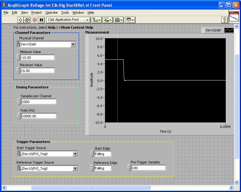
PXI-4461: Acq & graph tension-Int Clk - dig Start & Ref .vi
Samples per channel = 1000
Rate (Hz) = 10000.00
Start the trigger Source = / [name of the instrument DAQmx] / PXI_Trig0
Onboard start = fall
Reference Source Trigger = DAQmx Device Name] / PXI_Trig0
Reference edge = fall
Trigger samples = Variable (100, 500, 900)
PXI-2567: Switch Scaning-SW Trigger.vi
Advance the output terminal full = / [name of the instrument DAQmx] / PXI_Trig0
Scan list = / [name of the instrument DAQmx] / ch0-> com0.
Scan list = / [name of the instrument DAQmx] / ch1-> com1;
Hardware configuration:
The PXI-2567 module controls an external relay that switches between the voltage of 5 V on ch0 and ch1 0 V.
The PXI-4461 connects to the COM of the external relay and therefore reads 5V when ch0 is connected; 0 v when ch1 is connected.
Procedure: The above examples are used in the following procedure.
1. run the PXI-4461 VI. A start trigger (falling edge) is necessary to start collecting samples before firing.
2. launch the module, PXI - 2567 VI. When ch0 is initially (and immediately) on com0, a trigger is sent to PXI_Trig0. The PXI-4461 will begin to acquire samples before firing.
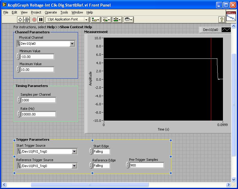
3. - click on the "Connect to the next" button on the front of the PXI - 2567 VI module. This sends a trigger to entry software for the PXI-2567 module and the transitions of the scan for ch1-> com1 list. Once the PXI-2567 module remains (debounced), advanced complete relaxation is sent on PXI_Trig0 for the PXI-4461. The PXI-4461 will begin to acquire samples after outbreak.
Note: Instead of the trigger of the software entry, an external input trigger can be used (e.g. PXI_Trig1).
Results:
> Before instant release of samples = 100
Delay is caused by the time of actuation of external relay.
> Before instant release of samples = 500
Delay is caused by the time of actuation of external relay.
> Before instant release of samples = 900
Delay is caused by the time of actuation of external relay.
I hope that the attached screws and the explanation above helps you and/or other customers who have this problem.
Best regards
Chad Erickson
Switch Product Support Engineer
NOR - USA
-
With a sampling of the data with DAQMX, error-200279 occurs when making 2d array dbl
Hello
I did a system of simple analog voltage with DAQMX data acquisition.
It is made for reading of capacitance, where output capacitance value out of a circuit in the periodic voltage signal.
What I want is to get data from four capacitors simultaneously through four channels, using samples n n (dbl 2d).
The structure of my VI is almost similar with examples of continuous sampling of voltage in LabView, with the exception of a few other calculations in the loop.
And for the synchronization of the trigger, I've corrected the edge of release with the external signal from the capacitance reading circuit.
Version no. 1 has a channel for data input voltage. Version n ° 2 has four channels for the input data.
While ver.1 can get accurate reading of four capacitors circuit data each (a single channel at a time),.
ver.2 acquires four channels of data, with a single thin data channel, all the others were wrong.
I saw a 200279 error occur in the DAQMX read part 2d dbl, so I tried increasing the buffers by changing the sampling frequency or the number of samples, but it wasn't everything.
I rose for most of the forums with the 200279 error, but the solution would not work on mine.
Anyone can find the problem? I will attach my screws it may include a bit of Korean language, but most of them are in English, shouldn't be too hard to recognize. Sorry for the inconvenience.
Oh I forgot, my DAQ is NI USB-6259, and it works in Win XP sp3 and LabView 8.6.
Thank you.
Hello Azurenight,
The 6259 is a DAQ card of the M Series Multiplexed, which means that it is not possible to sample each signal at the same instant, rather the channels are all sent through the ADC even and must be sampled in order. More information on this can be found here:
LabVIEW Help: Multiplexing compared with simultaneous sampling
http://zone.NI.com/reference/en-XX/help/370466W-01/mxcncpts/multisimulsamp/
It may still be possible to get the data you need with the card you have - could you give more information about the maximum eligible period between samples on different channels?
If you require * real * simultaneous sampling, you will probably need different hardware.
Kind regards
-
I have a question about the order of execution. In the WHILE loop, I have two things to measure, period and tension using the DAQmx READ functions for voltage and the meter. In the end, I want to collect these data as points almost simultaneously as possible, as a pair and then send them together to another piece of code (not shown here) which them will result in some sort of command for an engine. It would be run, and then I want to perceive the tension and the period at a time later and do the same thing.
(1.) I'm a little confused on what the meter of the READ function is back because it's a table. What is a picture of? I thought that it was up to the value of the individual periods between rising edges. The output of the counter 1 DBL d's a table. How many elements in this table, and what determines the size of this table? Are the elements of the array the individual delays between the edges? How many values are stored in the array by executing? We take the AVERAGE of the last 15 items, but do not know if we are throwing some of the data or what. How to understand the composition of this painting? How can I change the composition of this painting? Is it possible to measure only one period at a time, for example the time between TWO edges?
2.) Will this WHILE loop execute as it gathers tension and a "period table ' (remains to be understood by me) by TIME running in a loop? In particular, we want that the value of the tension associated with the value of the AVERAGE of the period "array", so we can use two data items to create orders of next control every time that the two values are reported. The structure for the delivery of vi will be attached data in pairs like this? I understand that one of the READING functions run not before the other function of READING in the WHILE loop. I want that the period "means" and "strain (Volt) collected at the same pace. This vi will he?
Thank you
Dave
Hi David,
I suggest including the DAQmx Start Task function. If it does not start before the loop, it starts the loop and work very well, but it is not as fast and efficient. In the model of task status, task wiill go to run the checked each iteration of the loop and then back the time checked running when it restarts.
The status of the task model: http://zone.ni.com/reference/en-XX/help/370466V-01/mxcncpts/taskstatemodel/
Kind regards
Jason D
Technical sales engineer
National Instruments
-
Hello
I'm reading 8 channels at once using the NI9213 and DAQmx (see attached image). With this configuration, the loop takes ~ 500ms each iteration. What can I do to improve this?
Thank you
JP
You have not coded anywhere, anytime, so it runs at default speeds. Look at the examples DAQmx as Thermocouple - continuous Input.vi. Your module even has a mode high speed, that you can use for a very fast acquisition. Read the manual.
BTW, the wires DO NOT your mistake byte of WILL in the end to end eventually. Always connect them so you can control the errors during debugging.
-
Repeating the trigger with Start.Retriggerable
I have a DAQ PCI-6259 (M-series card) card I am programming with DAQmx. I would like to know if there is a limit in terms of how close together you can use Extensible triggers. I intend to use a frequency of internal clock to 1us. An asynchronous external TTL signal will be used to trigger a finite sequence of digital output of the 6259. The finished digital sequence is 4 samples of long, so it will take 4us. The edges of the asynchronous trigger will happen on every 100us. I intend to use the property Start.Retriggerable = TRUE trigger so that I can repeat this generation 4 sample every time the external TTL signal is received.
Is 100us too close together? Is there a limit to how closely together, you can repeat a hardware trigger when using Start.Retriggerable = TRUE?
Is it possible to know if my card PCI-6259 even supports the property trigger Start.Retriggerable?
100 US will be very well (time to rearm is the order of a tick or two, 10 timebase s ~ ns).
However, the M series supports digital output directly redeclenchables not. Instead, configure a redeclenchables counter finished output to generate impulses 4 to 1 MHz (this example uses two counters embedded M-series). Use the output of the internal counter as the sample for a task of digital output clock continuous who will repeat your 4 sample sequence.
Best regards
-
How to open files using the Scan Disk card reader
original title: scan disc card reader
I copied pictures from my phone using this method, scan disc card reader. This is a new laptop, but this should not be so difficult! The laptop does not recognize the card reader, but I do not remember how I can't simply click, icon, & my pictures should appear as if by magic. "Why don ' t they?
Sincerely,
Sandra AmmermanI copied pictures from my phone using this method, scan disc card reader. This is a new laptop, but this should not be so difficult! The laptop does not recognize the card reader, but I do not remember how I can't simply click, icon, & my pictures should appear as if by magic. "Why don ' t they?
Sincerely,
Sandra Ammerman===================================================
Something to try...OK... you have an external or internal USB media player?
Insert the memory card into the correct location on the media player...
If open windows... Close them.When the card is inserted... If you go to... Start / computer... is
player card on one or several removable disks?
(You could say, "devices with... of removable storage")Removable (e :)) drive
Removable disk (e :))
Removable drive (g)If_Yes_you can download photos from there. Left click
the drive letter that corresponds to the memory card must
display the directory of the card and you can copy and paste or
Drag and drop the photos of your choice in a folder on your hard drive
drive.Just a select group of photos do a right-click and choose... Copy...
then navigate to the folder that you want, and then right-click the
folder and choose Paste.Also, adjust your AutoPlay settings may be worth a try:
Windows 7 - change settings for importing pictures and videos
http://Windows.Microsoft.com/en-us/Windows7/change-settings-for-importing-pictures-and-videosWindows 7: AutoPlay: frequently asked questions
http://Windows.Microsoft.com/en-us/Windows7/AutoPlay-frequently-asked-questionsWindows 7: Troubleshoot AutoPlay
http://Windows.Microsoft.com/en-us/Windows7/Troubleshoot-AutoPlay-problems -
Problem of Windows vs Mac OS with socket read/write and LabView
Hello
I inherited, multithreaded code, with a singleton that communicates with LabView via few ports/sockets. I don't know (but don't think) mention it in this case multithreading issues, but in case you think there could be a problem. All communications to the LabView through LabView class (instance) singleton.
When we run the code on the same box of MS Windows XP as the LabView so, it works properly; This means that LabView receives orders and the java receives the results. When we run it on a Windows XP box in another room with another subnet it works fine as well. When we run a Mac OS in the same room/network reader.ready () is not true in the time-out period. (see the line of reader.ready () in the original code).
Does anyone know why it would work for Windows but not Mac OS?
A current "guess" what is bad on my part, is that code below (taken out of context, otherwise the position would be really long) needs of some rethinking. Any help/comments/advice on how it is encoded is greatly appreciated.
Here are the existing code.
In particular, I have readLine() in a loop where I catch the exception if it is not read and just keep trying? What is the "best way" to do?// some declarations. long t0, t1; long waittime = 5000; BufferedReader reader; public synchronized void connectCommPort() { if (commportconnected != true) { try { sock = new Socket(); InetSocketAddress endpoint = new InetSocketAddress(IPaddress, commPort); sock.connect(endpoint, 4000); // try to connect with a timeout of 4 seconds. reader = new BufferedReader(new InputStreamReader(sock.getInputStream())); writer = new PrintWriter(sock.getOutputStream()); System.out.println("mec: LabV: SUCCESS - network connection to Labview command port succeeded"); commportconnected = true; errorstatus = false; } catch (IOException ex) { logwriter("LabV: WARNING - network connection to Labview command port failed."+ex.toString()); System.out.println("mec: LabV: WARNING - network connection to Labview command port failed."+ex.toString()); commportconnected = false; errorstatus = true; } } } public synchronized float readpot(int potnumber) { String smotor = Integer.toString(potnumber); if (potnumber >= 0 && potnumber <= 5) { String message = "pot " + smotor; connectCommPort(); if (commportconnected) { try { writer.print(message + "\r\n"); writer.flush(); logwriter("LabV: [sent] " + message); potvalue = potlistener(); } catch (Exception ex) { System.out.println("mec: Exception while sending command "+ex.getLocalizedMessage()); } disconnectCommPort(); } } else { if (potnumber == 7 || potnumber == 6) { potvalue = 5.f; logwriter("Faked pot reading for potnumber " + potnumber); } else { logwriter("WARNING: " + potnumber + " is not a valid pot number (must be 0 to 6)"); } } return potvalue; } public synchronized float potlistener() { String message = null; t0 = System.currentTimeMillis(); t1 = System.currentTimeMillis(); boolean donereading = false; while ((t1 - t0) < (waittime) & donereading != true) { t1 = System.currentTimeMillis(); try { while (reader.ready()) { message = reader.readLine(); logwriter("LabV: [received] " + message); if (message.contains(".")) { potvalue = Float.parseFloat(message); } donereading = true; } // close reader-ready-while } catch (Exception ex) { System.err.println("Exeption in potlistener() "+ex.getLocalizedMessage()); } } // close timeout while loop return potvalue; }
Here's what I thought, something like:while ( ((t1 - t0) < waittime) && !donereading ) { t1 = System.currentTimeMillis(); try { message = reader.readLine(); logwriter("LabV: [received] " + message); if (message.contains(".")) { potvalue = Float.parseFloat(message); donereading = true; } } catch (Exception ex) { System.err.println("Exeption in potlistener() "+ex.getLocalizedMessage()); } } // close timeout while loop(a) No, but I would look into the configuration of the network itself rather than the Java code.
(b) the correct way to enforce a timeout of read is through Socket.setSoTimeout ().
-
Help? the source volume is read-write and can not be disassembled...
I use 10.11.5 on an iMac 21.5 ", end of 2009 and I want to restore the OS X 10.11.5 to HD on an external drive but I get this message" Source volume is read = write and cannot be disassembled, so it cannot be copied from block. " I can find answers do not address El Capitan. Help would be greatly appreciated.
.. .Goldie
You use disk utility's restore feature?
If the HD has a recovery partition, you can make starting in place of the recovery.
Or you can use SuperDuper! (the basic version is free and can copy the entire disk, the paid version allows "smart updates", which copies only files that are different, saving time) running on externally to perform the copy.

Maybe you are looking for
-
Missing components in my file Ultiboard if I transfer my file Multisim
Hello! I am after this Introduction: http://www.NI.com/white-paper/10710/en/?CID=Direct_Marketing---em80795&espuid=CNATL000018702741 On the point 5. the part D: transfer to PCB Layout "" (8) select transfer "transfer to Ultiboard ' transfer to Ultibo
-
RT warning flag target CompactRIO
Because I'm having a problem with IMAQ Vision, as seen in this post, I decided to pop in for LabVIEW 2013 installation disk and I'm having a problem of getting up and running. http://forums.NI.com/T5/LabVIEW/IMAQ-not-compatible-with-LabVIEW-2014/TD-p
-
What versions of 32-bit window based on HP G62-144DX laptop
Hi all I bought the new computer hp laptop g62 and OS is win7 64 bit and RAM is 4 GB. I want to change to 64 bit to 32 bit OS, because an application cannot install to there. for example: I can not install the oracle 10g database. What version of 32-
-
NAVADIACONTROLPANELUNSTALLVIRUS
THISISEMERGENCYNAVADIACONTROLPANNELUNSTALLVIRUS
-
I had a problem with my sound card
Hello worldI have a problem with my laptop. This morning, while I was enjoying my music (from media window), my friend called me by Skype. After that, my sound stopped working so far. I don't even know why. Y does it have that someone has the same pr