Replace the flat sequence Structure?
I read a bit in the forum and a lot of people discouraged to use the structures of the sequence. Here's the situation: I have a tick count at the beginning for the iteration (and another at the end). I want to force them to count before (and after) anything else. The code I'm working on leash all data through structures flat sequences that contain only tick counts. Is there a different way that you can do without the structures of the sequence?
Thans
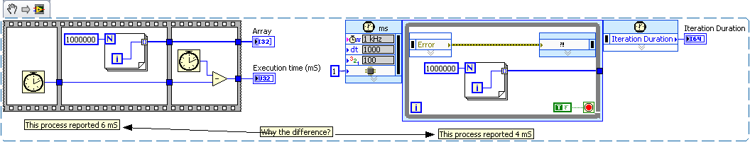
The recommendation not to use structures of sequence applies to most of the cases where people use. State machines are the preferred (and best) method. However, this does not mean that there is never a good use for a sequence structure. In your case, when you both want something, it is perfectly acceptable. An example is shown in the first snippet below.
There is an alternative however. You can use a timed loop to time your code. Someone posted here once an example. I forgot who he was and who puts in. It went something like the snippet of the second.
I would like to know why there is a difference in speed between these two methods:
Tags: NI Software
Similar Questions
-
Scripts (connect a Terminal to a flat sequence Structure)
(script)
Is it possible to connect a terminal to a flat Structure of the sequence? (in my case, with a single frame)
(with the "Connect Wire" method)
Ouadji wrote:
but the main question is... Why the flat sequence structure does not inherit from node?
Why the developers chose this?
What is the main idea of this choice?Flat sequence Structure introduced in LabVIEW 7.0, provides a semantic schema object that no other object has. It is a structure of multi-frame (like a case structure or a stacked sequence), but it is the only structure where data can be wired between frames through normal tunnels. It is the only structure which may have tunnels in places other than its external borders. It is the only structure that can have subdiagrams of different sizes in different positions. It also introduces scenarios of strange wiring that you won't find elsewhere:
At the same time that the flat Structure of the sequence was introduced, there was enough of these bizarre scenarios with scripts (which was an internal feature NOR at the time), it was easier on the developer to make his own script class to try to find a way to support it under an existing class. We had no idea that script would become a public service someday, so the burden was relatively low and limited within the walls of NOR. Looking back, there have been enough problems with the FlatSequence class in the script than most of us agree that it would be better to have it in class Node (or more precisely, the class MultiFrameStructure) from the beginning.
-
Delay the time of flat sequence Structure?
How to delay the moment of execution for flat sequence Structure?
Your question is a little vague.
You want to delay in a certain amount of time? Until something happens?
You can add a primitive frame with a wait.
It might be useful to you could reach a simplified example so that we can better see what you're doing.
-
The speed of the flat sequence?
Hello
What I want to do: read a map OR 6 analog voltages and provide a few analog/digital outputs from another card of NEITHER.
Here's what I do: I use the DAQ assistant to acquire 6 different analogue voltages on a simulated map of NI 9205. I tried to run at the same time all 6 data acquisition assistant acquires (which did not), but I read that since there is only a single clock on the map, so I can not use multiple acquires at the same time because of timing issues (right?). Then, I put my DAQ assistants in their own images in a flat sequence then they would be operated sequentially. This works fine, but each frame/acquire takes 1 second to complete. Which means that my program lasts 6 seconds to do everything acquires it, before my other code outside the plate sequence. Outside platform sequence are my trips (some digital and analog a bit on a slider). Because my flat sequence lasts 6 seconds to compete, my outputs are updated only once every the 6 seconds, where as before the flat sequence has been inserted that they have been updated little almost instantly.
Here are the questions: can I do the flat sequence run faster? Or is there a way to simultaneously acquire several analog voltage using the DAQ assistant. I feel that I shouldn't need to the apartment of sequences, but do not know a better way to go about it.
I hope that makes sense and I'm pretty new to labview so feel free to add many details.
Thank you!
PS: If you try my Vi, notice how slowly the 3 top entries in the page update, if I remove the huge flat sequence, they run very quickly and smoothly, which is what I would like.
e g m e n i wrote:
Here's what I do: I use the DAQ assistant to acquire 6 different analogue voltages on a simulated map of NI 9205. I tried to run at the same time all 6 data acquisition assistant acquires (which did not), but I read that since there is only a single clock on the map, so I can not use multiple acquires at the same time because of timing issues (right?).
Instead of trying to run 6 assistants for the acquisition of data in parallel (or sequential), use one assistant DAQ who reads all channels simultaneously.
-
Scripting - reference control Replace inside the flat sequence
Hello
Just in the process of upgrading our software from 8.6 to 2011. A question that we have is references appear to be different to the old code. Example - if we create a new control reference, put it next to the old one, put a probe on the two, references do not match when we run the vi.
This causes havoc with our very large amounts of code. We contacted OR that our support subscription and they required an example which we can really give.
In any case...
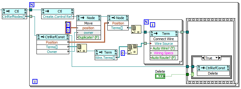
I thought that I would write a vi script to replace all old references of our code with new references.
Problem is that I can't replace a control easily reference which is inside any kind of structure.
I need a way to get a reference to a parent structure, I can then add to the structure.
This will take place on large amounts of complex code, so there need to be versatile. Please see the attached Vi
Thank you
Joe
I would like to make the following changes:
- You'll want to use the 'Move' method, which allows you to specify an owner. In this case, the owner is the schema that belongs to the original control reference.
- You want to get the original order wire and get all its wells (i.e. not null index into the array of terminals), so that you know what to wire the new benchmark in control of. That is why the Connect wire method is in a loop For... the original control reference may have wired to several objects.
Let me know if you have any other questions. As far as I know, all properties/methods that I am using the code above are available in LabVIEW 8.6.
-
How to create flat sequence structure and add Subvi with true or false on an another flat following?
How can I create next. flat and add a colum with VI and true Sub VI falseSub?
What should be the flowchart:
-
CONNECT OF PREREQUISITE for the flat table structure?
I am familiar with data such as the following and extract a hierarchy using CONNECT BY PRIOR:
For example:
with tbl_data AS
(
SELECT 'PZPZZZZ' code, 'LEVEL1' code_level, 'Kingdom' code_label, NULL      parent_code FROM DUAL UNION ALL
SELECT 'PZ2ZZ2Z' code, 'LEVEL2' code_level, 'Phylum ' code_label, 'PZPZZZZ' parent_code FROM DUAL UNION ALL
SELECT 'PZ3ZPZZ' code, 'LEVEL3' code_level, 'Class '  code_label, 'PZ2ZZ2Z' parent_code FROM DUAL UNION ALL
SELECT 'PZ433PZ' code, 'LEVEL4' code_level, 'Order '  code_label, 'PZ3ZPZZ' parent_code FROM DUAL UNION ALL
SELECT 'PZ5535Z' code, 'LEVEL5' code_level, 'Family ' code_label, 'PZ433PZ' parent_code FROM DUAL UNION ALL
SELECT 'AAZZZZ2' code, 'LEVEL6' code_level, 'Genus '  code_label, 'PZ5535Z' parent_code FROM DUAL
)
SELECT     LPAD(' ', (LEVEL - 1) * 10, ' ') || code
         , LEVEL
         , parent_code
         , code_label
      FROM tbl_data
START WITH code = 'PZPZZZZ'
CONNECT BY PRIOR code = parent_code;
That generates data like this:
HIER                                                        LEVEL   PARENT_CODE CODE_LABEL
----------------------------------------------------------- ------- ----------- ---------------
PZPZZZZ                                                     1                   Kingdom
          PZ2ZZ2Z                                           2       PZPZZZZ     Phylum
                    PZ3ZPZZ                                 3       PZ2ZZ2Z     Class
                              PZ433PZ                       4       PZ3ZPZZ     Order
                                        PZ5535Z             5       PZ433PZ     Family
                                                  AAZZZZ2   6       PZ5535Z     Genus
We have some data stored in a table with this structure, finance so that instead of data as in the example above, the hierarchy is stored in a single line - for example
with tbl_data AS
(
SELECT 'PZPZZZZ' level1, 'Kingdom' level1_desc,  'PZ2ZZ2Z' level2, 'Phylum' level2_desc, 'PZ3ZPZZ' level3, 'Class' level3_desc, 'PZ433PZ' level4, 'Order' level4_desc, 'PZ5535Z' level5, 'Family' level5_desc, 'AAZZZZ2' level6, 'Genus' level6_desc FROM DUAL
)
SELECT level1
     , level1_desc
     , level2
     , level2_desc
     , level3
     , level3_desc
     , level4
     , level4_desc
     , level5
     , level5_desc
     , level6
     , level6_desc
  from tbl_data;
Data:
LEVEL1  LEVEL1_DESC LEVEL2  LEVEL2_DESC LEVEL3  LEVEL3_DESC LEVEL4  LEVEL4_DESC  LEVEL5  LEVEL5_DESC LEVEL6  LEVEL6_DESC
------- ----------- ------- ----------- ------- ----------- ------- -----------  ------- ----------- ------- -----------
PZPZZZZ Kingdom     PZ2ZZ2Z Phylum      PZ3ZPZZ Class       PZ433PZ Order        PZ5535Z Family      AAZZZZ2 Genus
Given that the data is in this format, it is possible to generate a query of the hierarchy, assuming level5 is the parent of level6, level4 is the parent of level5 and so forth, to generate the same output as the example above?
Is not a work at home on the interview question - just something I try to appear at work, for my own interest.
Any advice would be much appreciated.
Thank you
with tbl_data AS
(
SELECT level1 "PZPZZZZ", "Realm" level1_desc, "PZ2ZZ2Z" level2 "Phylum" level2_desc, level3 'PZ3ZPZZ', 'Class' level3_desc, level4 'PZ433PZ', 'Order' level4_desc, level5 'PZ5535Z', 'Family' level5_desc, 'AAZZZZ2' level6, 'Like' level6_desc FROM DUAL
)
Select decode (x
, 1, level 1
, 2, lpad (' ', 10). Level2
, 3, lpad (' ', 20). Level3
, 4, lpad (' ', 30). Level4
, 5, lpad (' ', 40). Level5
, 6, lpad (' ', 50) | Level6
) yesterday
x
decode (x
, 2, level 1
, 3, level 2
, 4, level3
, 5, level4
, 6, level5
) parent_code
decode (x
, 1, level1_desc
, 2, level2_desc
, 3, level3_desc
, 4, level4_desc
, 5, level5_desc
, 6, level6_desc
) yesterday
of tbl_data
(select level x from dual connect by level<= 6="">
-
on the flat sequence and time elapse
My goal is to make the second picture of work after 1 second. I used two different methods in the attachment first and second. The first was performed well while the other fails. I don't see why the difference exists. Everything that I have done is to justify the delay time is greater than 1.
He turns to 1. However, I strongly recommend that you stay away from the dyanamic data. As you can see, it is converted to a digital and Boolean. The result of a superior function, must be a Boolean, and that would be something that you could not connect directly to a digital. You can connect dynamic data what either, and the result of that, I think can be a little unpredictable.
-
Sequence structure flat inside the timed loop and execution order
I have some problems trying to implement a flat sequence structure when you use a loop timed on a target of cRio VI
I tried with or without the while loop around the structure of sequence flat, and I also tried to replace the 'Non-deterministic loop' with a timed loop
The problem is that the program seems to run only once, then get stuck somewhere
I am writing a program that performs the following operations as soon as possible:
1. read the Pos_MC of entry on the FPGA
2 send the value of Pos_MC to the VI target (on cRio CPU)
3. calculate a value of output based on Pos_MC with a PID block ("exit PID')
4. send 'PID output' to the FPGA
5 write "PID output" analog output "MOOG".In addition, I want the program to return the measured value "Pos_MC" to a host VI for the recording of data
So that the output of PID is calculated and sent to the FPGA as quickly as possible, I placed a flat sequence structure to ensure that it happens before you send the output to the nondeterministic loop for recording data
Also, I want the digital input 'Stop' to be able to stop the loop deterministic (the timed loop)
I read much more entries than that and the help of several PID and exit, but I rewrote the code for a single entry and exit to make it easier to illustrate
Screenshot of the code is shown in 'target code.png' and 'fpga code.png.
The VI themselves are attached in the next post (cannot attach files of more than 3)
Question 1:
Any advice on how to get this race? Thank you!Question 2:
Is also my correct understanding in that, using this structure, each 0.9ms (fpga loop time) comes the following:
1. the input ("Pos_MOOG") is read on the fpga
2. the production of PID is calculated on the cRio with some delay to computation (for example 0.1ms)
3. the output of PID is then written for analog output "MOOG" in all about 0, 1 - 0.2ms
4. the FPGA program then waits until 0.9ms spent and repeat the processAs opposed to the next pass whenever performing a loop is started on the FPGA:
1. the FPGA reads the input and written on the output (the output of the execution of the previous loop PID)
2. then the entry is sent the cRio, PID output is calculated and sent to the FPGA
3. the new release of PID is maintained until the next time through the loop
Thank you!
PHG wrote:
Thanks for the input guys, any advice as to how I could get the feature in scenario 1?
I still say that the best route is just putting all the logic of the control in the FPGA.
Other alternatives include 1) the use of DMA FIFO sedn data back or 2) use interruptions so that the FPGA code can not read the output level until the RT.
DMA FIFOs are usually very limited, and I would not use them in this situation since I belive said it this code to do for the many outputs.
-
How to turn on the flat Structure of sequence based on a Boolean value?
Hello
I try to write a (attached) VI who enjoy an analog voltage that crosses one analog multiplexer. I am using a flat sequence structure to change the output of select signals to change the channel to be sampled. I wonder if I can turn on the structure when my Boolean input of the sample is TRUE?
Based on the image (I can't watch the VI himself), he doesn't seem to be a necessity for the sequence at all. There is data connections Wizard DAQ to two scalar indicators, which implies that you are taking a single sample. No need to acquire multiple samples and throw all but one. The second sequence is certainly unnecessary.
-
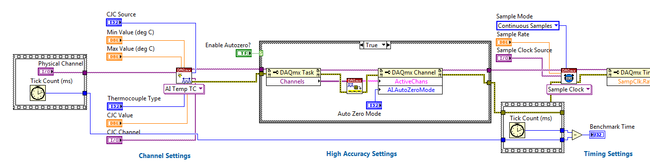
structure of flat sequence for benchmarking
Hello
Maybe this is very obvious, but I don't completely understand something with the sequence flat structures-FSS (I never use this structure by the way and I don't you not why they use it in this example).
There's a doc OR online explaining some mistakes of rookie in LV:
http://www.NI.com/newsletter/51735/en/
The doc has described that the FSS is useful for benchmarking, the BD:
My question: what if we put the number of cycles in a Subvi left and right and giving the exec. order with wires of the error? Or using a while loop that runs only once (with sons of error through)?
These 3 different ways are the same?
Yes, you can do all these things - I think that the only thing to keep in mind is that you do not want your benchmarking code to affect the speed of the code - otherwise, you'll get inaccurate results. If you use the while loop, you will need to do something to make sure your second number of cycles will run after your time loop - for example with FSS

Flat sequence structure using is OK - it's overuse of it which is a common rookie mistake - trying to force things to run in a specific order (for example if from a text based on the sequential programming language) instead of understanding that this is done by data flow in LabVIEW.
I think that the reason is simply because the number of cycles VI doesn't have an entry so you cannot apply data flow. It is common to have a Subvi, which encapsulates the number of cycles VI with error/output wire.
-
Store values in the flat order
Hi all,
I have the problem as I would like to ask for help from the community.
I currently use the flat sequence to run two blocks of different functions for my VI. Therefore, there are two frames in the sequence of plate.
For the first image, I'd like to store the previously calculated value so that when I come back to the first frame again, I can use this value to calculate the next value. It's like the iteration. I am currently using registry to offset this.
The problem I have enconter is that when my VI goes to the second image, the values in the first image that is stored in shift registers have disappeared.
I didn't really need to use the shift registers. I want to just store the previous value so that I can use it again in the next round.
This is the VI to better illustrate my problem.
Thank you very much.
Keith Tan
Hi Keith,
the values in the shiftregister are only in the one frame. If you need also in two, then you must connect the wire of the output of shiftregister for the second image. If you need values of frame two Connectionwithsuchprocedures one, then put a loop around the sequence and also a shiftregister.
Mike
-
Zino 400 has stopped working; replaced the motherboard, worked for a minute then was arrested again.
My 400 Zino has stopped working; There was no signal on the screen, , but the hard drive and fan turn. (edited by OP 03/06/15, 3:07 pm AND). I assumed the problem was on the motherboard, so I bought a motherboard OEM reconditioned. After the replacement, the boot sequence begins, which is encouraging. I entered the Service number, and I've sailed through the Control Panel, the screen went black. Again, only the sound is the fan. I can turn it on with the power button, but the only way to turn it off is to unplug. Would it be the processor or is it possible that the new motherboard is bad? What should I do?
Miss_Gail
[What is the color of the light of the power button, is it solid or flashing ' see page 36]?
Is it "beeps". If there is, how [see page 33]?
Bev.
-
How do you get and replace the hp pavilion 3CR3050D6K LCD flat screen 20-b010
Pavilion 20-B010 screen has been damaged and is cracked. I would like to get a replacement manual or instructions on execution of Assembly and disassembly.
Hello @VB_Richard,
I understand that you need to replace the LCD screen on your desktop HP Pavilion 20 - b010 all-in-One PC and you would like a manual or instructions on how to perform the installation. The number of product of the screen, you'll need is 652255-001, which is the 20 "TN N-glare W - LED Non - ZBD Sam 250nits. With regard to the steps needed to install it I am you provide those below:
Before you begin: remove the back cover and bezel.
Removal of LCD Panel Kit
1. place the entire middle frame on a smooth flat surface.
2 detach the connector from the LCD backlight to the LCD.
3. remove the four screws that attach the LCD Panel to the Central frame - the screws will be on the high or low or the sides of the Board according to the manufacturer of Panel. Each manufacturer will have its own stencils for the location of the screw holes.
4. partially lift the bottom of the middle frame off the LCD screen.
5. unplug the LVDS cable from the Control Panel before completely up the average frame off the LCD screen.
Replacement LCD Panel Kit
1. to install a new LCD Panel, align the top of the middle frame on the LCD Panel.
2. connect the LVDS cable to the LCD screen.
3. lower the average frame completely on the LCD screen.
4. replace the four screws on the sides or the top and bottom of the Panel to fix the Panel on the Central frame. Use the location of the screws to the stencil for the manufacturer of the Panel that you are installing.
5. replace the backlight of the LCD screen connector.
If the new LCD Panel comes from a different manufacturer that the old LCD Panel, remove old backlight converter card connector and install the new connector on the card. The jury has stencils indicating the location of the connector backlight by manufacturer. Configure the jumpers on the card of converter to match the Panel manufacturers. Painted stencil on the chassis of the Middle table configuration of rider by the manufacturer.
I hope that I have answered your question to your satisfaction. Thanks for posting on the HP Forums. Have a great day!
-
In the case of flat sequence LED
Hello
I have 2 flat sequence event with 1 LED in each event. How can I turn on the LED when the start of the event and the OFF when the event ended before he will move to the next event.
Help, please.
Thank you
Those who are not in the sequence of events. These are individual images. Events in LabVIEW are something completely different. Based on your question it seems that you are not completely understand dataflow. A function/VI will run when all data on the cables connected to it is present. Stream can be used to enforce the execution order, but executives of sequence can also be used.
In your first picture if you wire a real constant for the Boolean value, you can control when the Boolean value is updated because there is no dependenct data between the numerical calculations and writing of the LED. So, if you want to turn on the front LED the first image, then you must add a frame before the first person where you set the indicator and the same thing at the end.


Maybe you are looking for
-
Has anyone got the coding device?
My motorcycle g 2nd generation crashes when you use this procedure: After you load a code PIN or password in settings, security, coding phone menu. After the restart is required code PIN or password. If you miss it identifies the password error or th
-
I do an online courses for NSW electoral office and I can't read the right side of the issues. I use Vista business and can not find the option to display, if that's what I have to edit to change the screen resolution. I have a Benq G monitor series
-
When I shut down my computer, I get a box that says: ccsvcHSt error end of program. Can someone help me with this. I have a Windows XP Home Edition. Thank you.
-
I use LV v7.1 and had a memory problem that I solved with the deallocation function. However, I would use the deallocation of anxious memory that existed as an Option. I don't see in LV7.1. Can I still put the switch in the INI file or that is no lon
-
Hey well when I started theme maker 5 closest setting my 9300 curve, that I could find was the curve 8900 and when I exported the theme on my phone, it did not work because I didn't have the right phone. It would still be the case if I hosted on app